Design of backdoor
OBJECTIVE
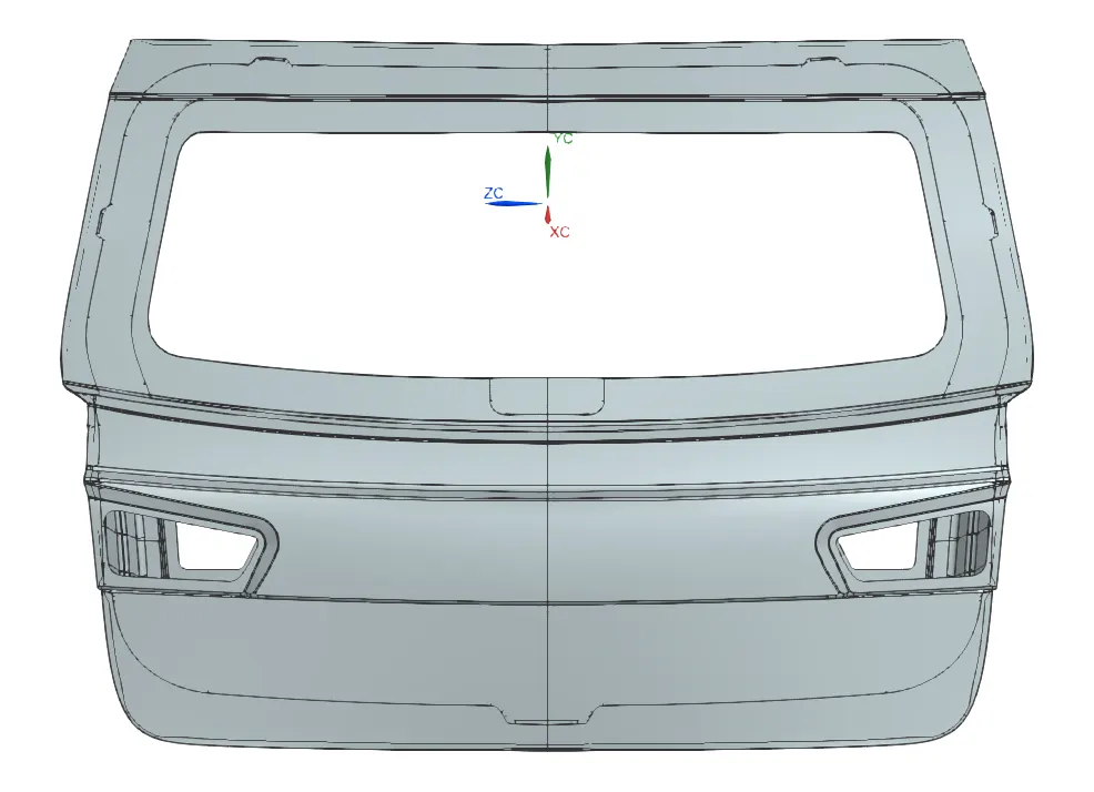
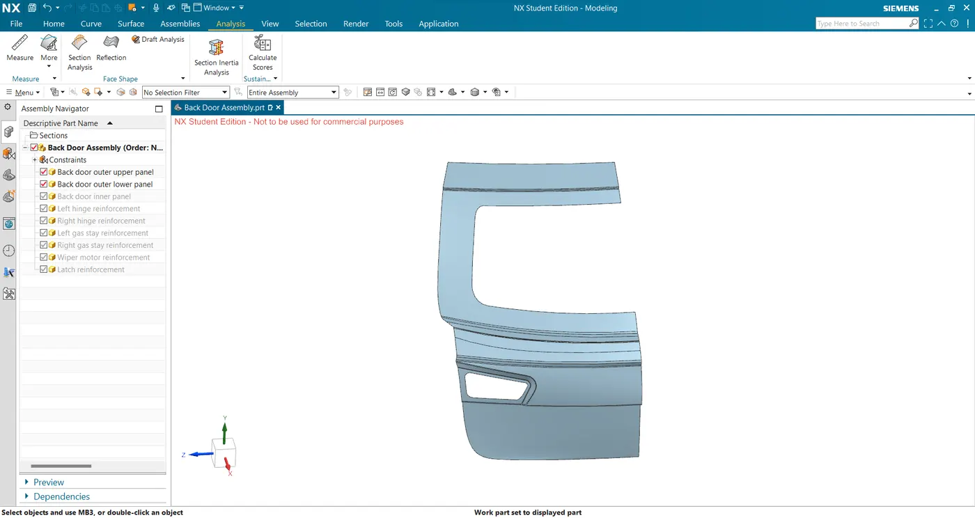
To design the Back door assembly of a vehicle using a given class-A surface in Siemens NX as a sheet metal component.
WHAT IS A BACK DOOR?
Just like any other door in a vehicle, the back door also serves a purpose for the ingress/egress of the rear area of the car. Its design calls for equal importance as during a rear collision it is the first to get affected hence its design should be such that the forces are diverted towards the structural members of the vehicle adding to the strength. It also houses different electronics and rear windshield glass.
Based on the mounting position, back doors can be classified mainly into the following:
- Top-mounted Back doors - Most hatchbacks and sedans come with this type of back door. they are mounted/hinged at the top and the user has to lift them up to access the rear end.
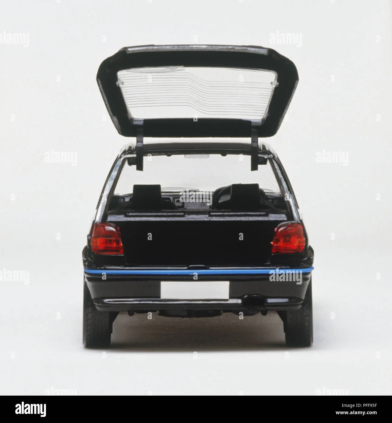
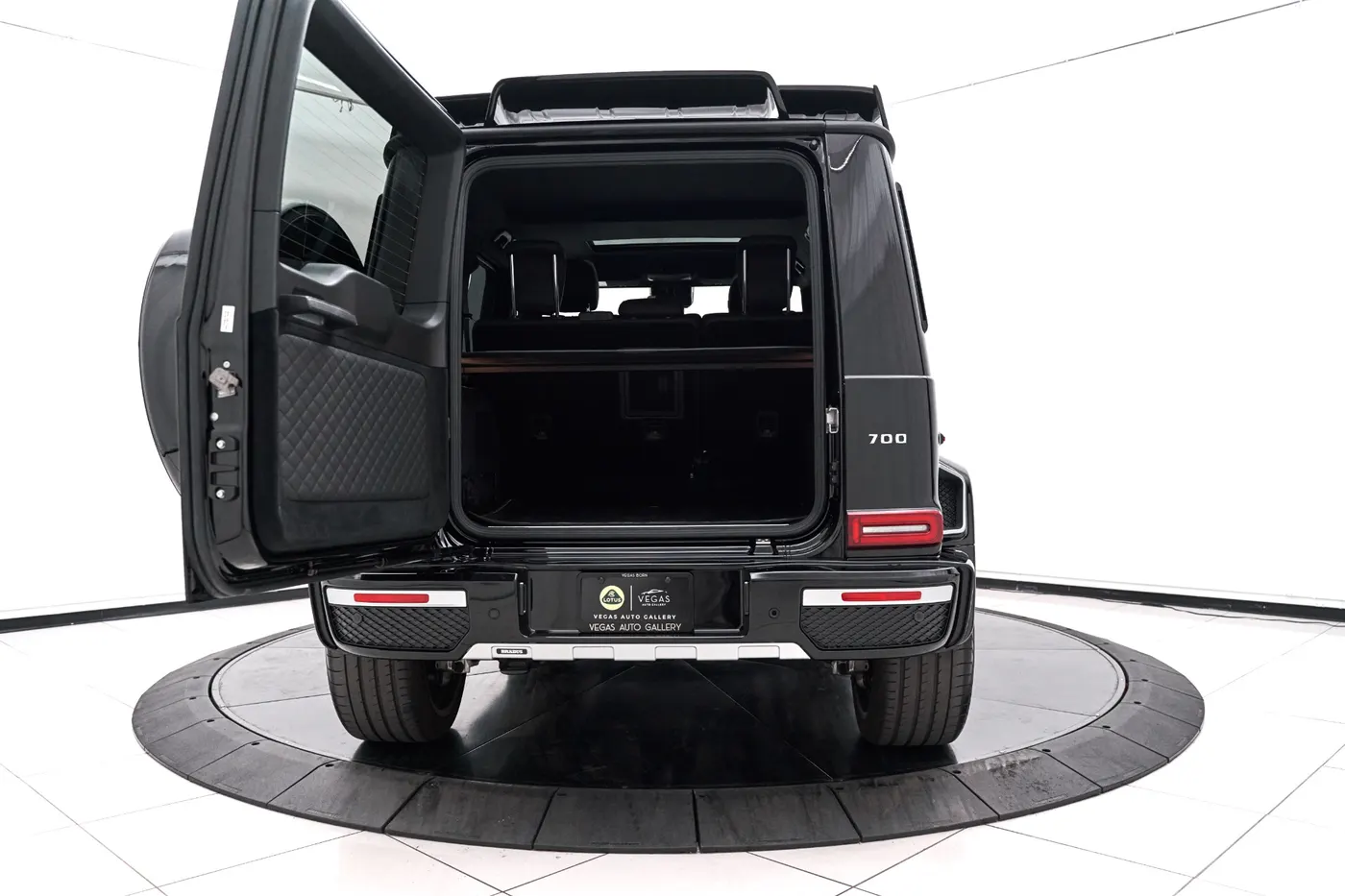
- Side-mounted back doors - they are mostly seen on wagons or SUVs. They sway open just like any other door of the car.
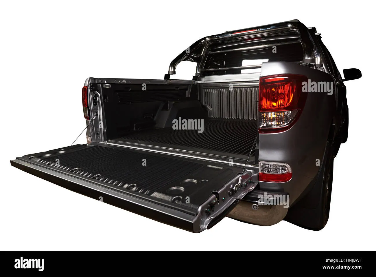
- Bottom-mounted back doors - These types of doors are mostly seen in pickup vehicles.
Based on the actuation system, back doors can also be classified mainly into the following:
- Gas stay operated - These doors are assisted by gas stays but require the initial opening thrust. Once opened, the gas stays keeps the door in open condition.
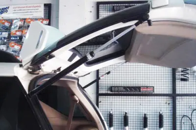
- Electric operated - These doors are powered by hydraulics which help lift the gate at the touch of a button without any prior assist.
COMPONENTS OF A BACK DOOR
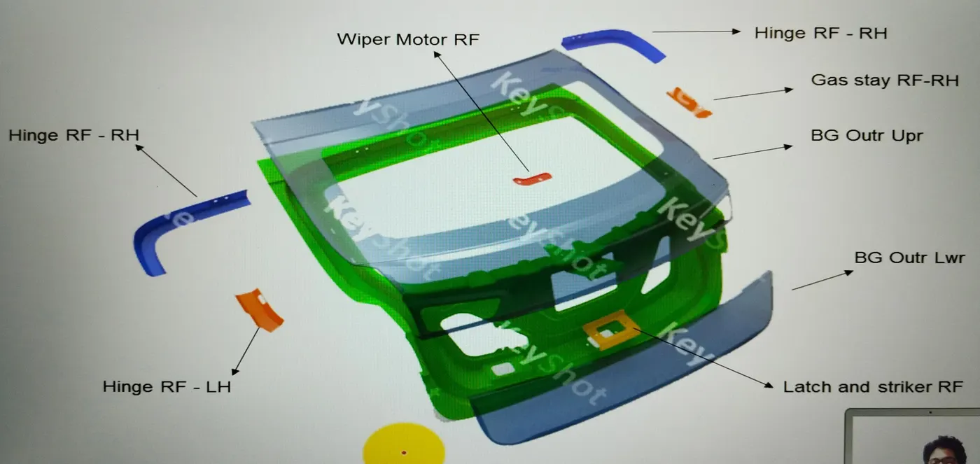
A back door assembly mainly consists of the following different parts:
- Outer panel
- Inner panel
- Hinge reinforcements
- Wiper motor reinforcement
- Gas stay reinforcements
- Latch reinforcement
- Interior trims
MANUFACTURING OF A BACK DOOR
A back door is manufactured by joining two different panels namely the outer and inner panels. Sandwiched between them are the reinforcement panels. The outer and inner panels are joined using spot welds and mastics. Spot welds are done in areas that are not directly visible to the eye to maintain looks. The outer panel is mostly fixed using mastic as spot welds may result in dents on the outer panel which will affect the looks of the overall back door.
The back-door design requires it to be strong and lightweight so, the material to manufacture these panels can be either
- Aluminium - It provides strength and is also lightweight. But it's expensive and hence is mainly used in high-end vehicles. Their manufacturing process involves casting which makes it easy for the varied thickness of the panel due to which there is no requirement for reinforcement.
- Steel - It is cheap compared to aluminium with great strength but has comparatively more weight. Most cars have their back door made from steel. Manufacturing panels from steel requires processes like stamping, deep drawing, punching, hemming, and embossing.
MANUFACTURING PROCESS OF A STEEL PANEL
The following processes are used to make individual panels of the back door
· Deep Drawing: It is a sheet metal forming process in which a sheet metal blank is radially drawn into a forming die by the mechanical action of a punch. This process gives the initial shape to the panel with the area for embossing. 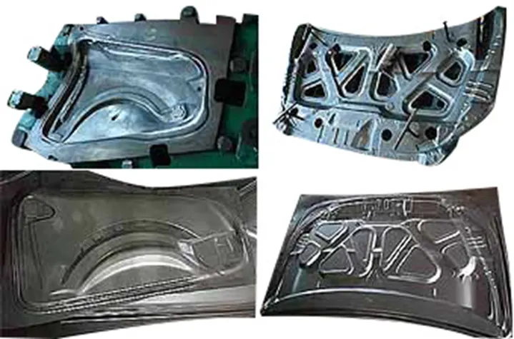
· Punching: It is a forming process that uses a punch press to force a tool, called a punch, through the workpiece to create a hole via shearing. the holes in the panel are made using this process. 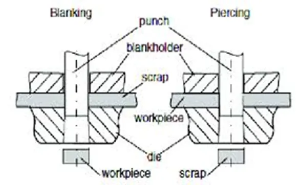
· Embossing: Sheet metal embossing is a stamping process for producing raised or sunken designs or reliefs in sheet metal. it is done to improve the strength of panels. 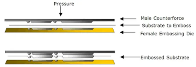
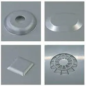
· Blanking: It is similar to the punching process except the punched material called the blank is the workpiece. The whole panel is blanked out from a bigger sheet of steel and later on, carried out for other processes.
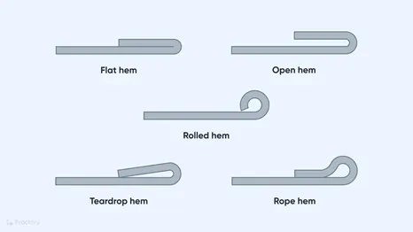
· Hemming: This is a process of joining two panels without using heat. It is achieved by folding the corner of a panel over the other panel. 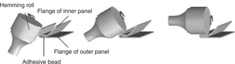
The backdoor is also tested for strength by different load tests to make sure the assembly is compliant. These tests are:
- Bend test
- Torsion test
- Abuse test
- Dent test
- Assembly load test
- Endurance test
DESIGN OF BACK DOOR
- Outer Panel Upper
- The given A surface has sharp corners which first need to be repaired for later operations to work smoothly.
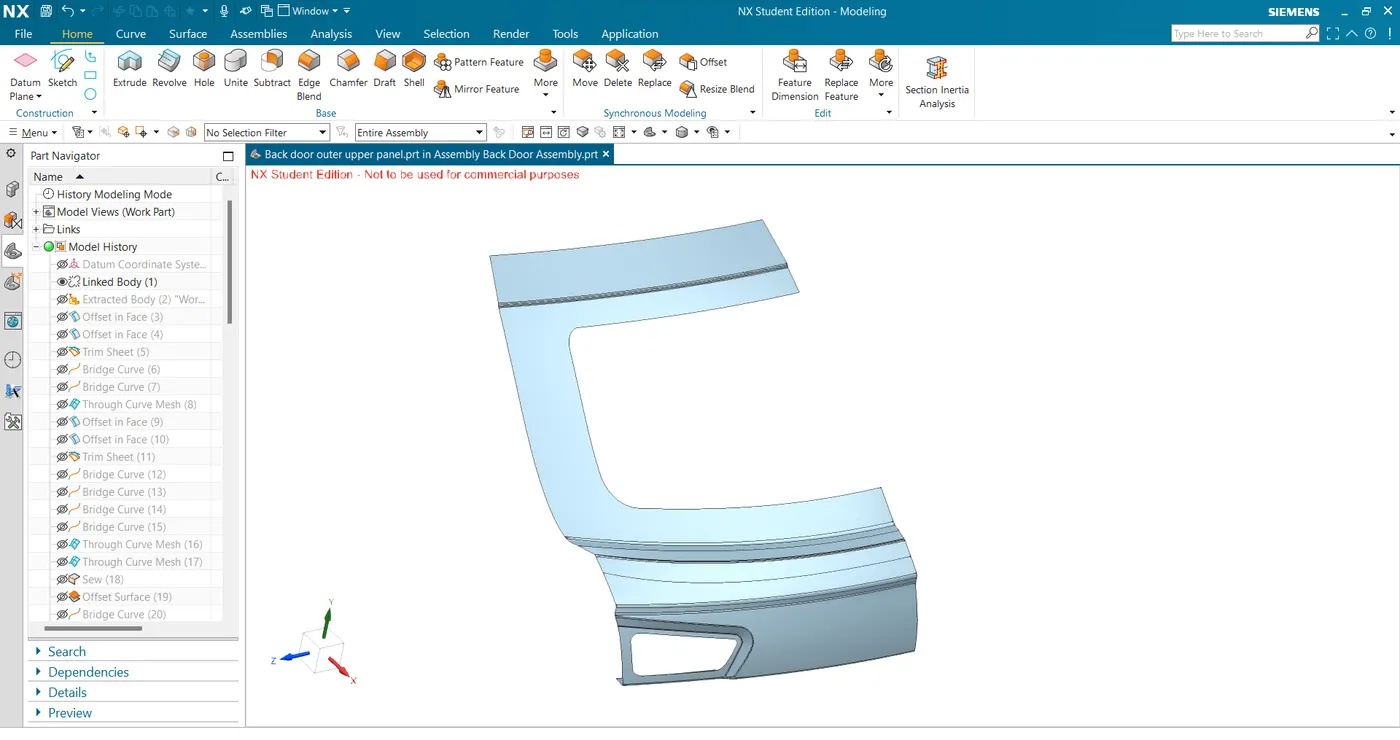
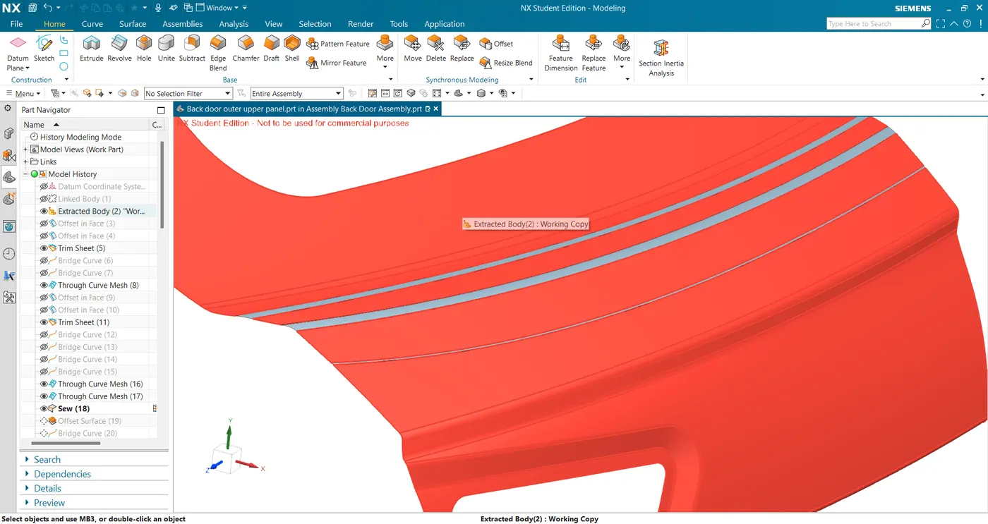
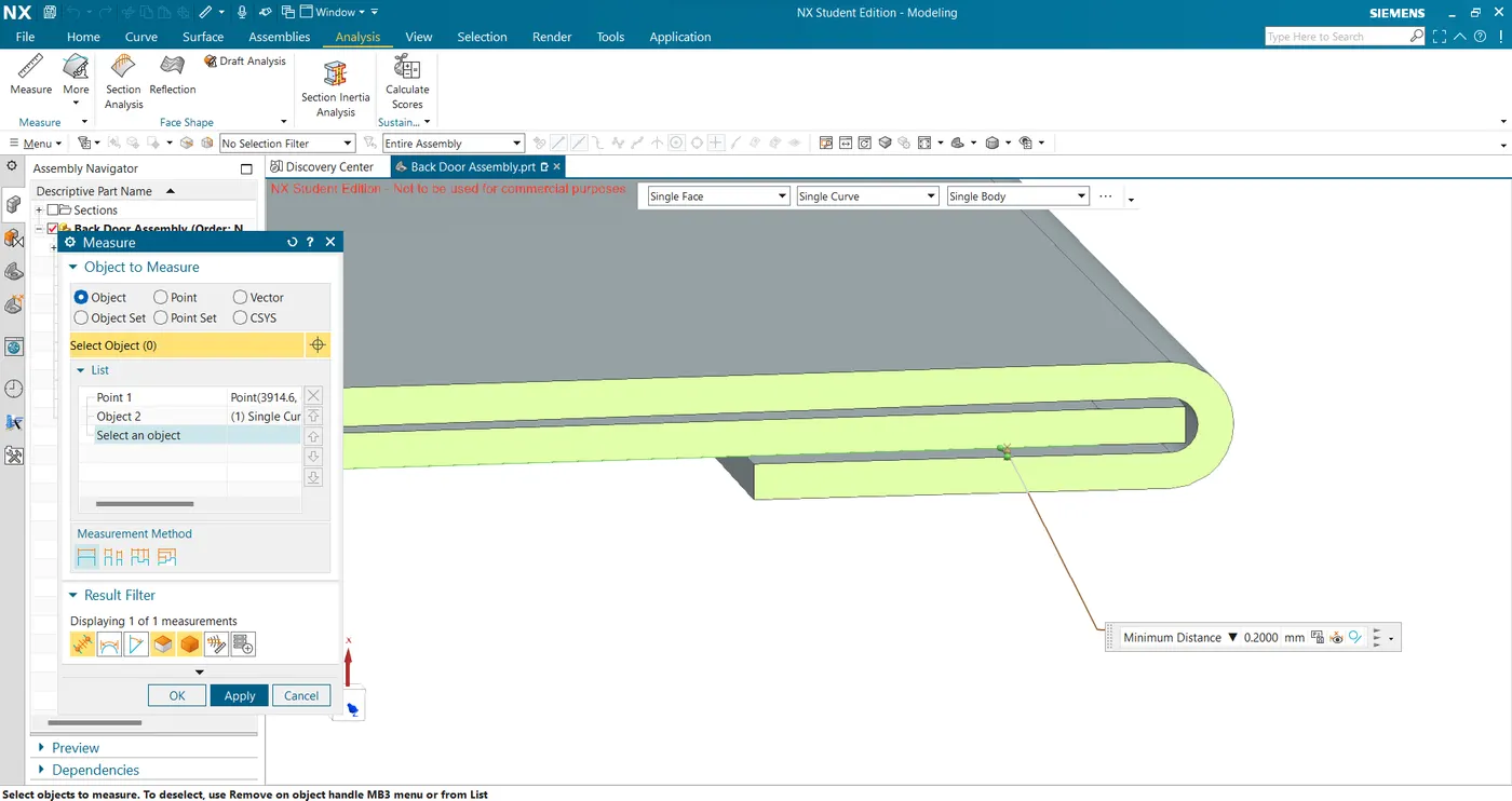
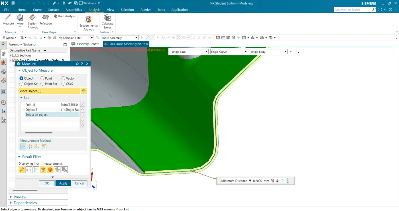
- For the hem flange, I offset the A surface by 2.65 mm (0.75 +0.2+0.75+0.2+0.75 mm) and repair a sharp edge using bridge curve with the face as constraint and trim the sheet.
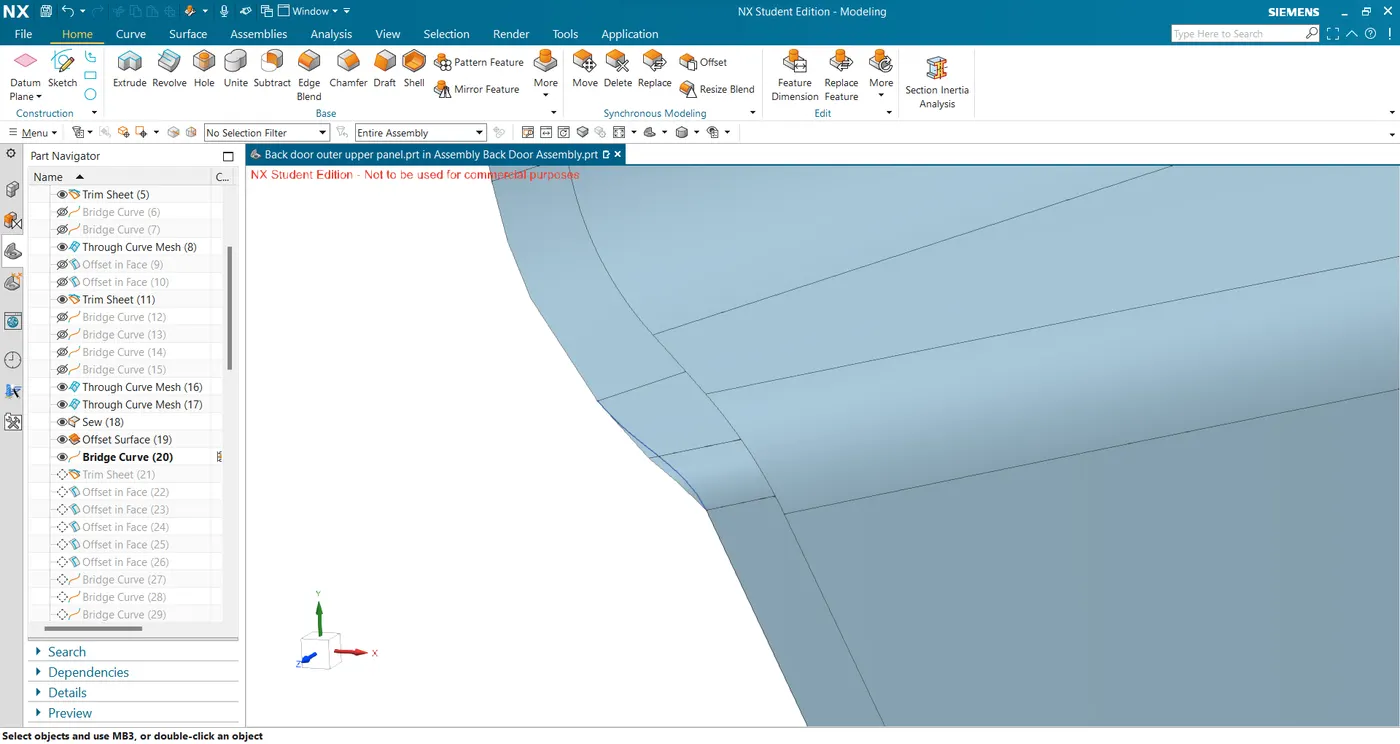
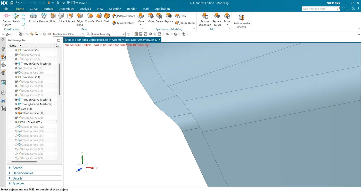
- Now on the offsetted surface, I offset the edge by 10mm on the panel. Repaired the curve and converted it to a composite curve and finally trimmed the panel to get the hem flange.
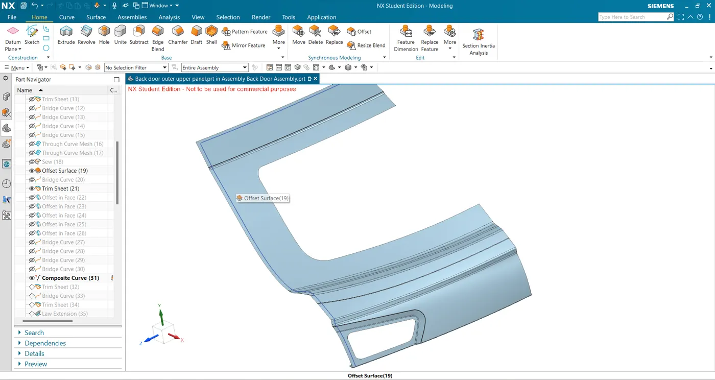
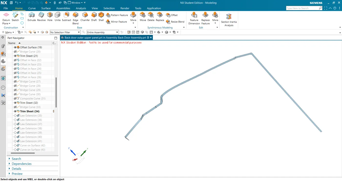
- Now to create the middle surface I used law extension on the hem flange edges and sewed them together to get the surface.
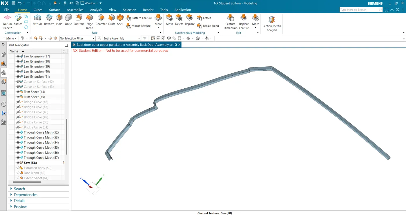
- Now I use the three-face blend with appropriate blend direction to get the hemming surface.
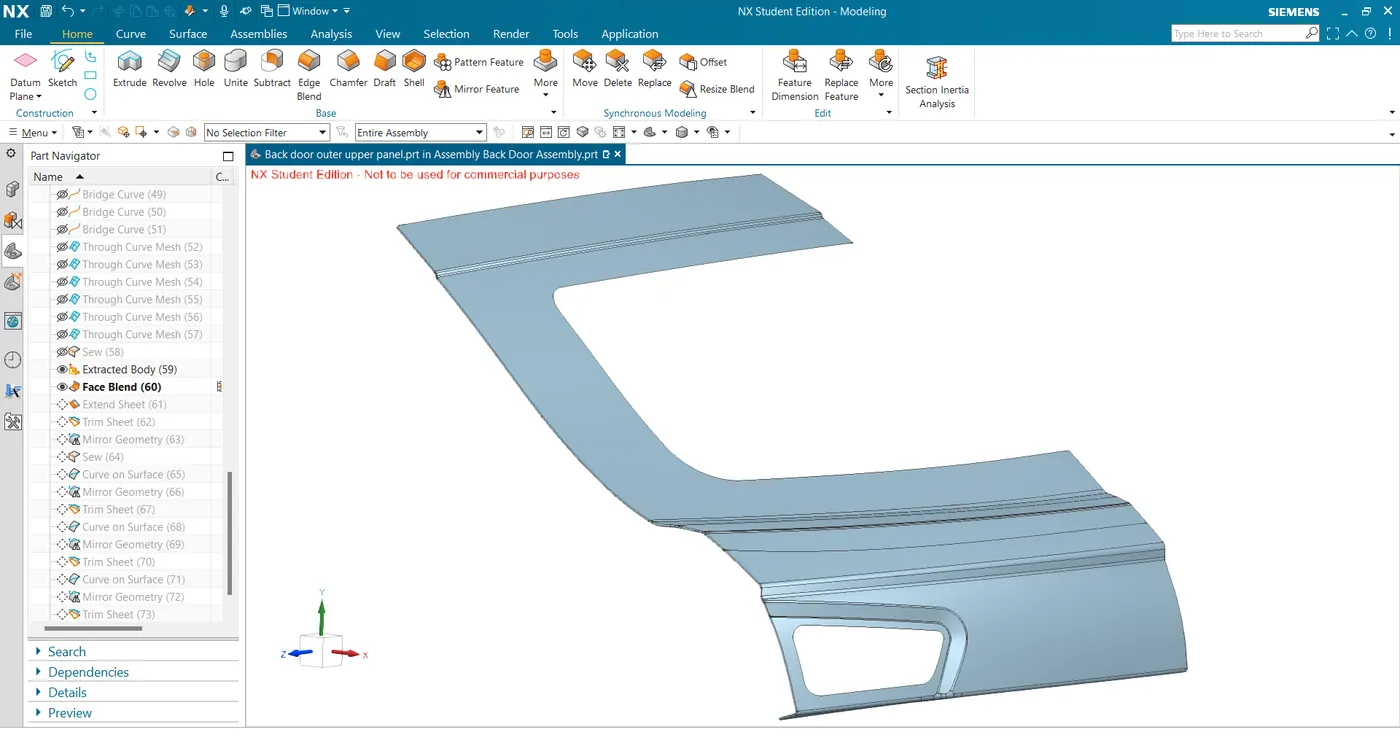
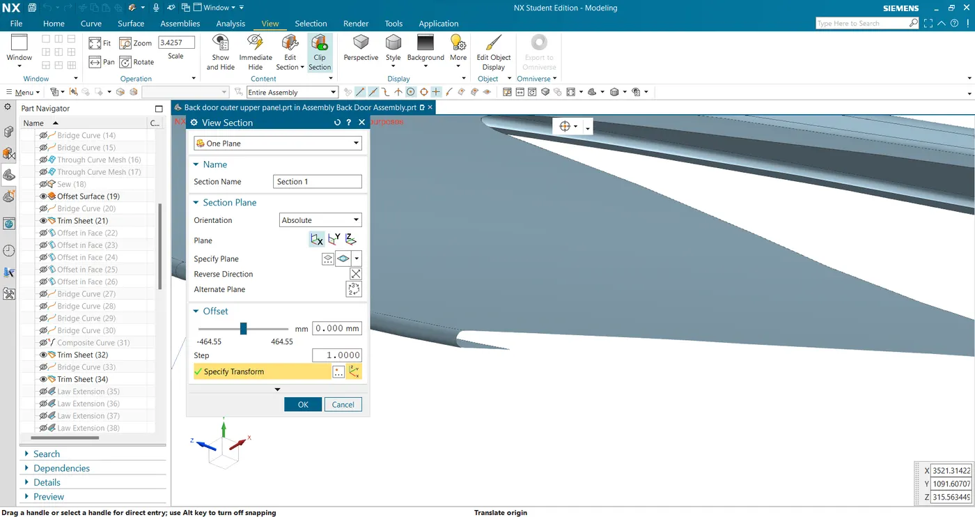
- I now mirror the panel and sew them together to get the complete outer panel upper.
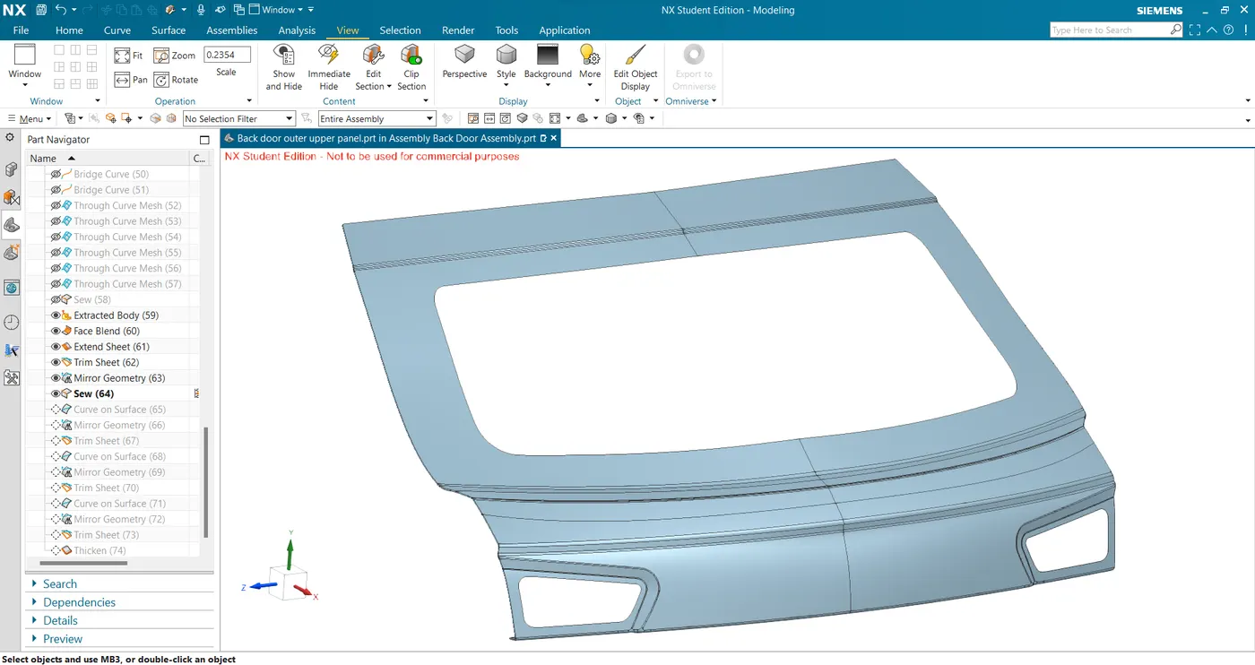
- I then used the curve in surface feature to create reliefs where there is a sharp turn to ease in hemming.
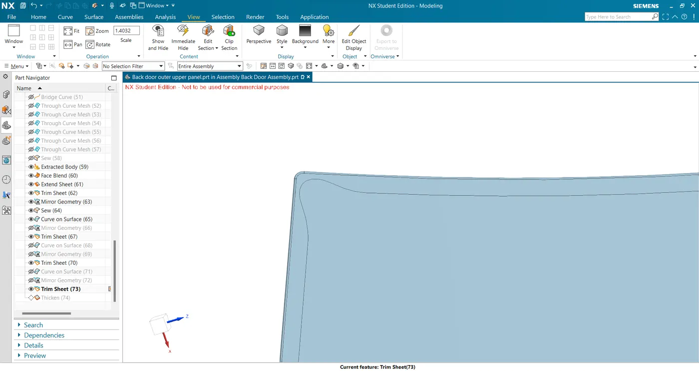
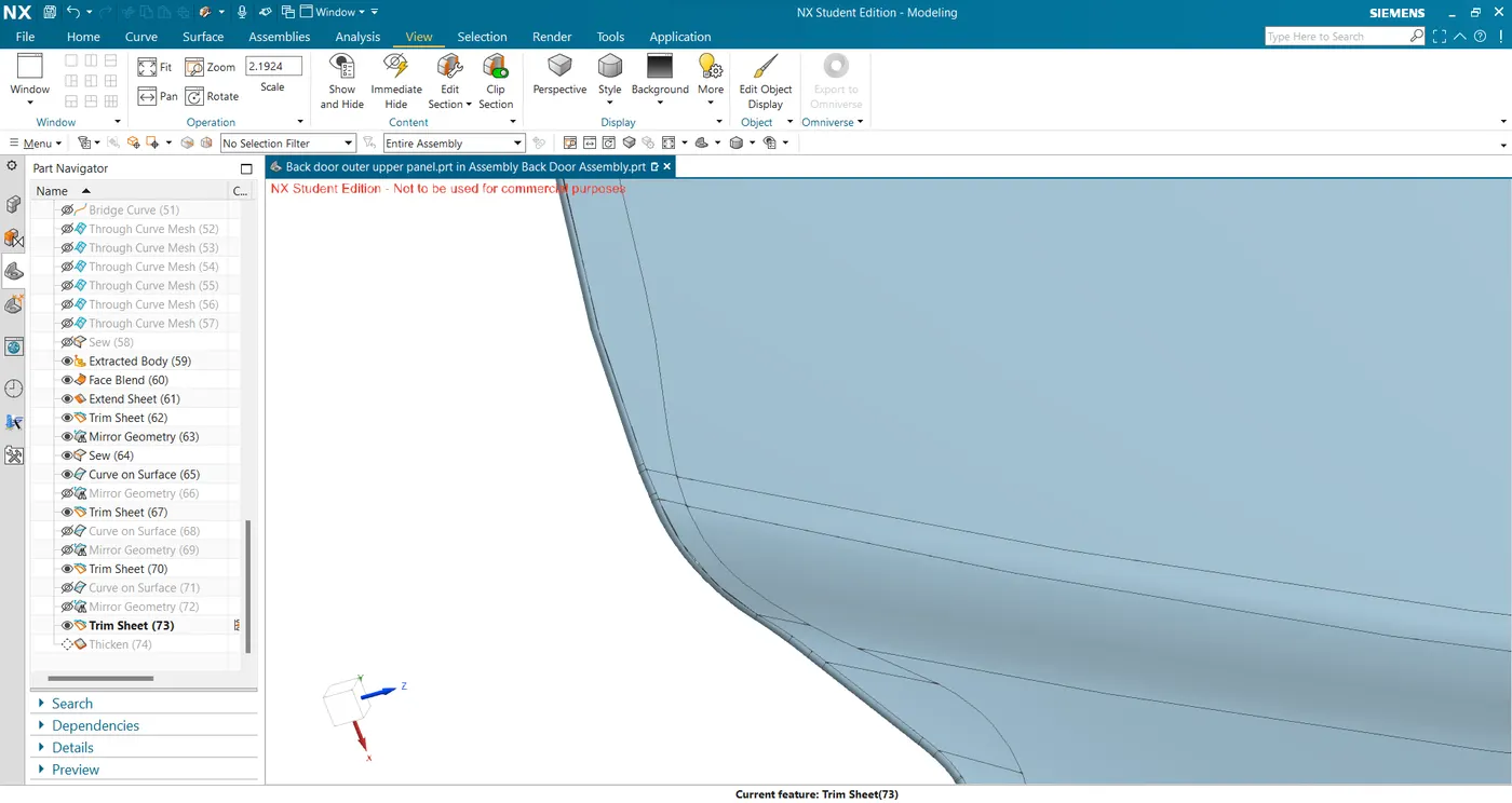
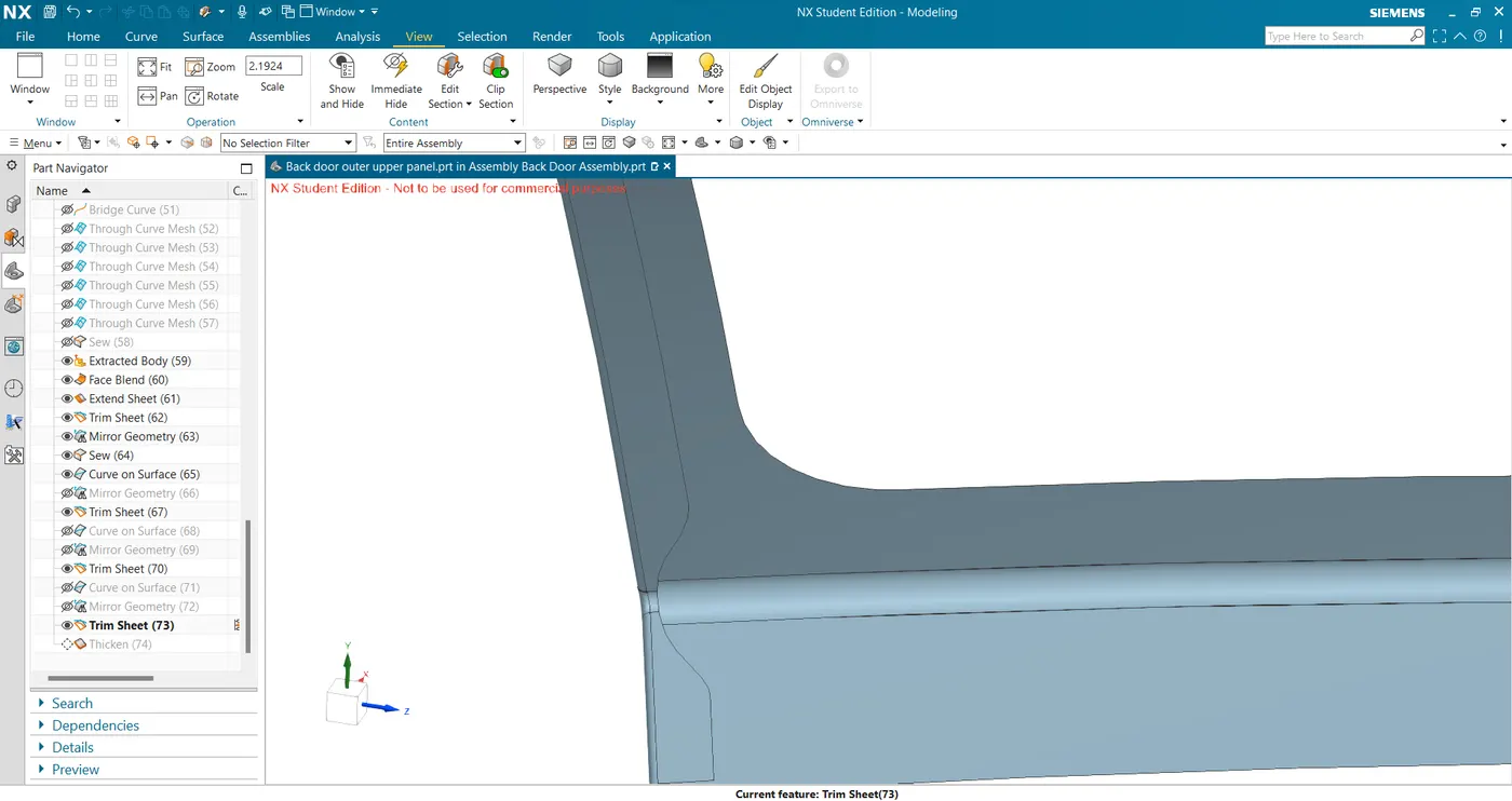
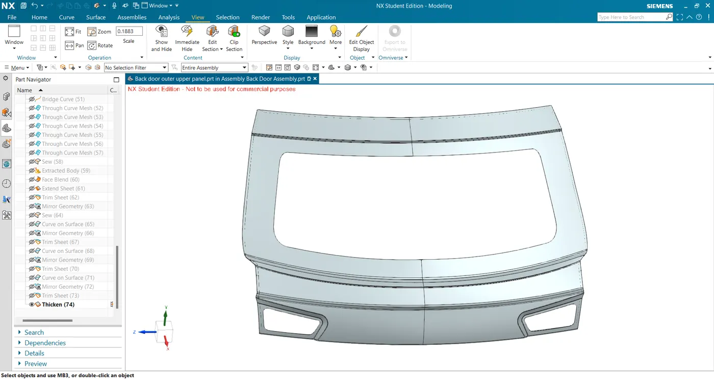
- Now I have the final surface which I thickened for 0.75mm inside to obtain the final part.
- The given A surface has sharp corners which first need to be repaired for later operations to work smoothly.
- Outer Panel Lower
- I created a mirrored geometry of the given A surface and sewed them together to obtain the complete lower outer panel surface.
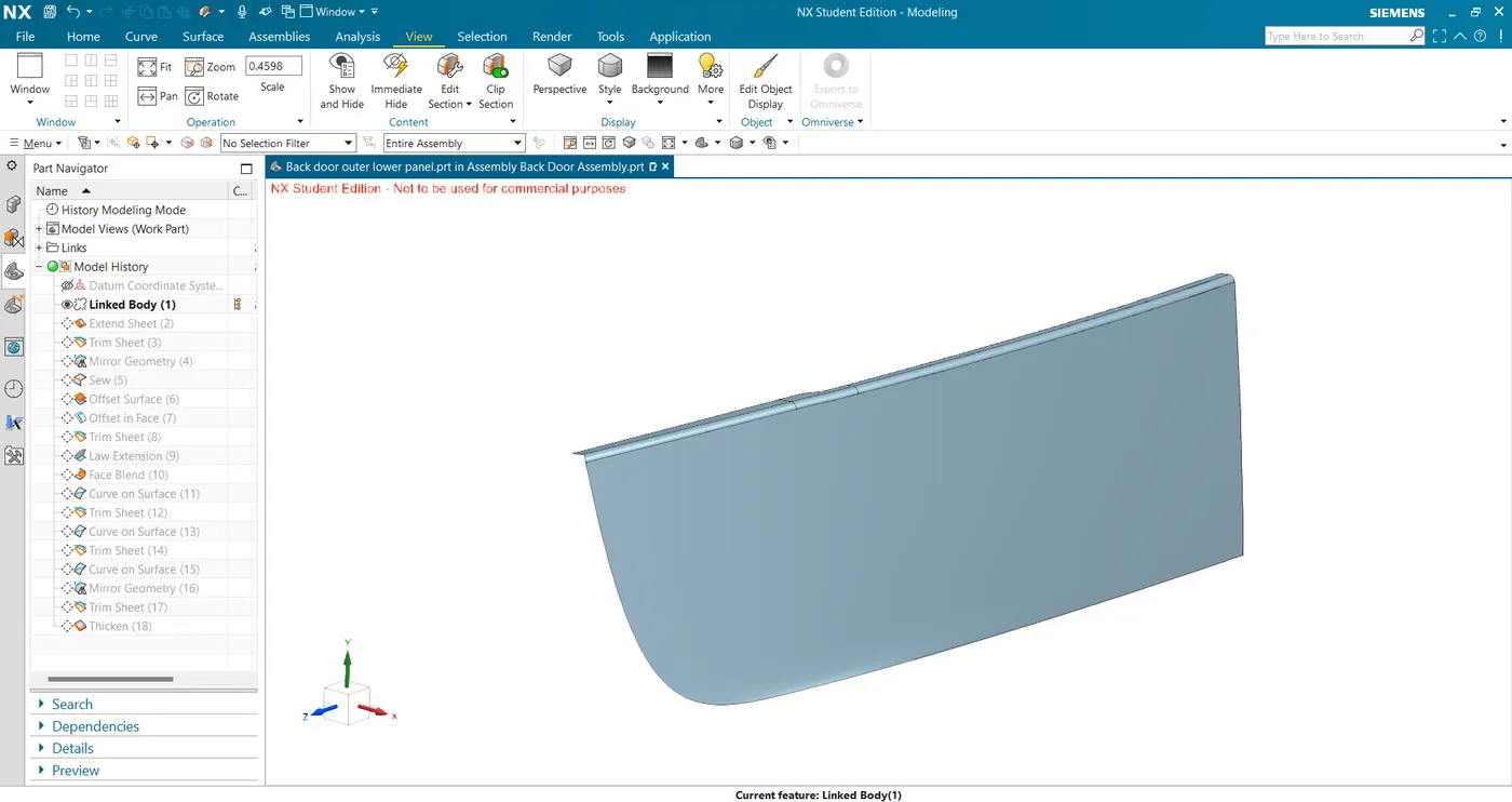
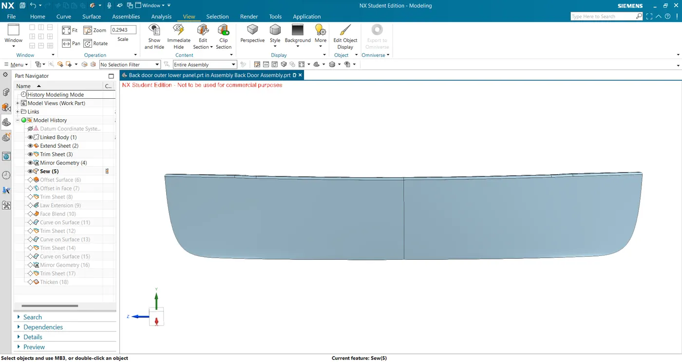
- For the hem flange, I offset the surface for 2.65mm and created the edge curve 10mm from the edges, and trimmed the panel.
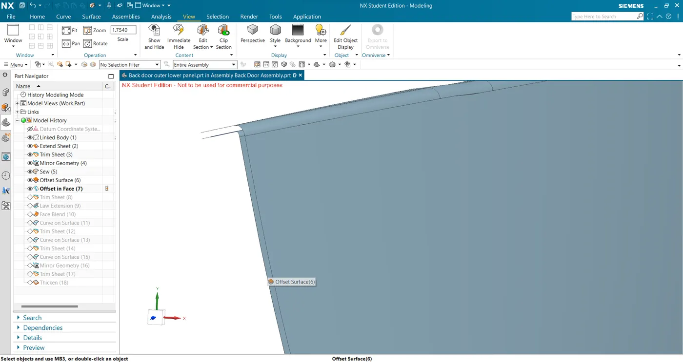
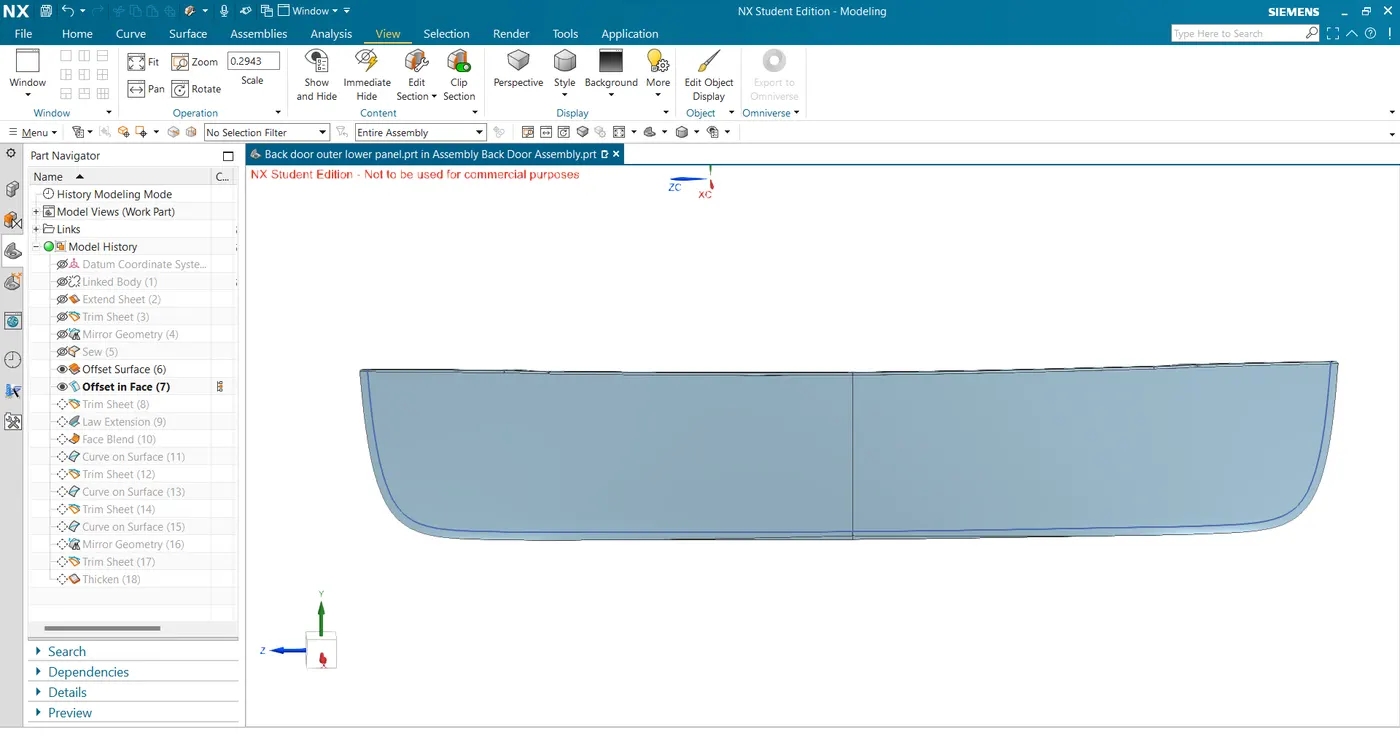
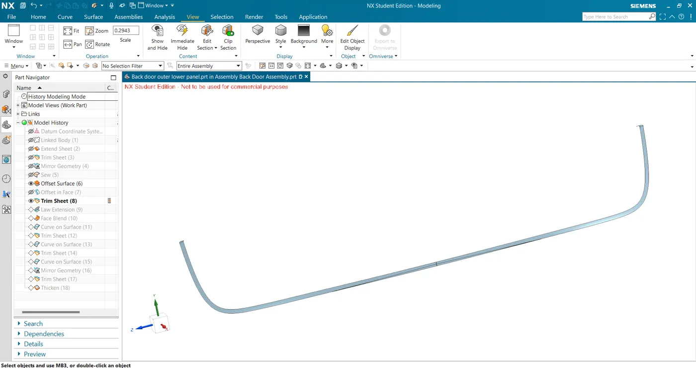
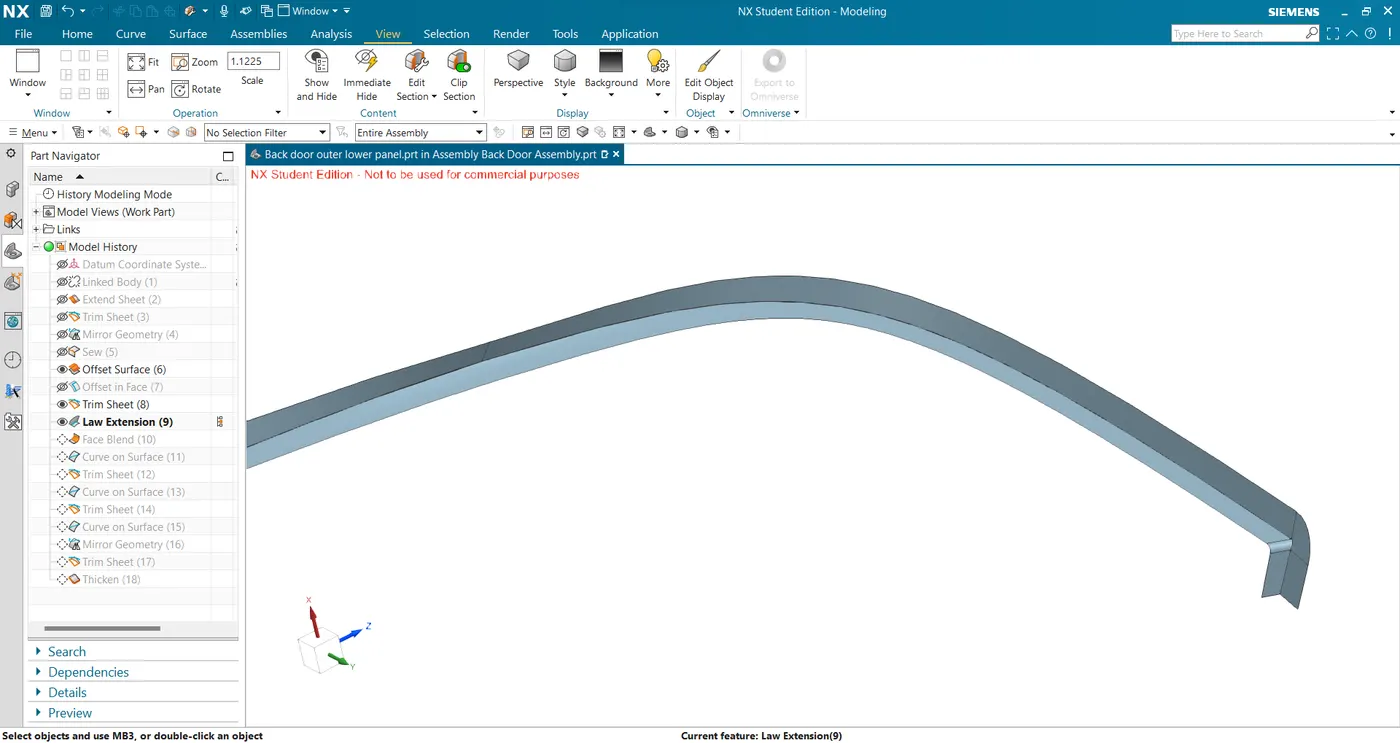
- I then used law extension at the outer edges of the hem flange to create the middle surface.
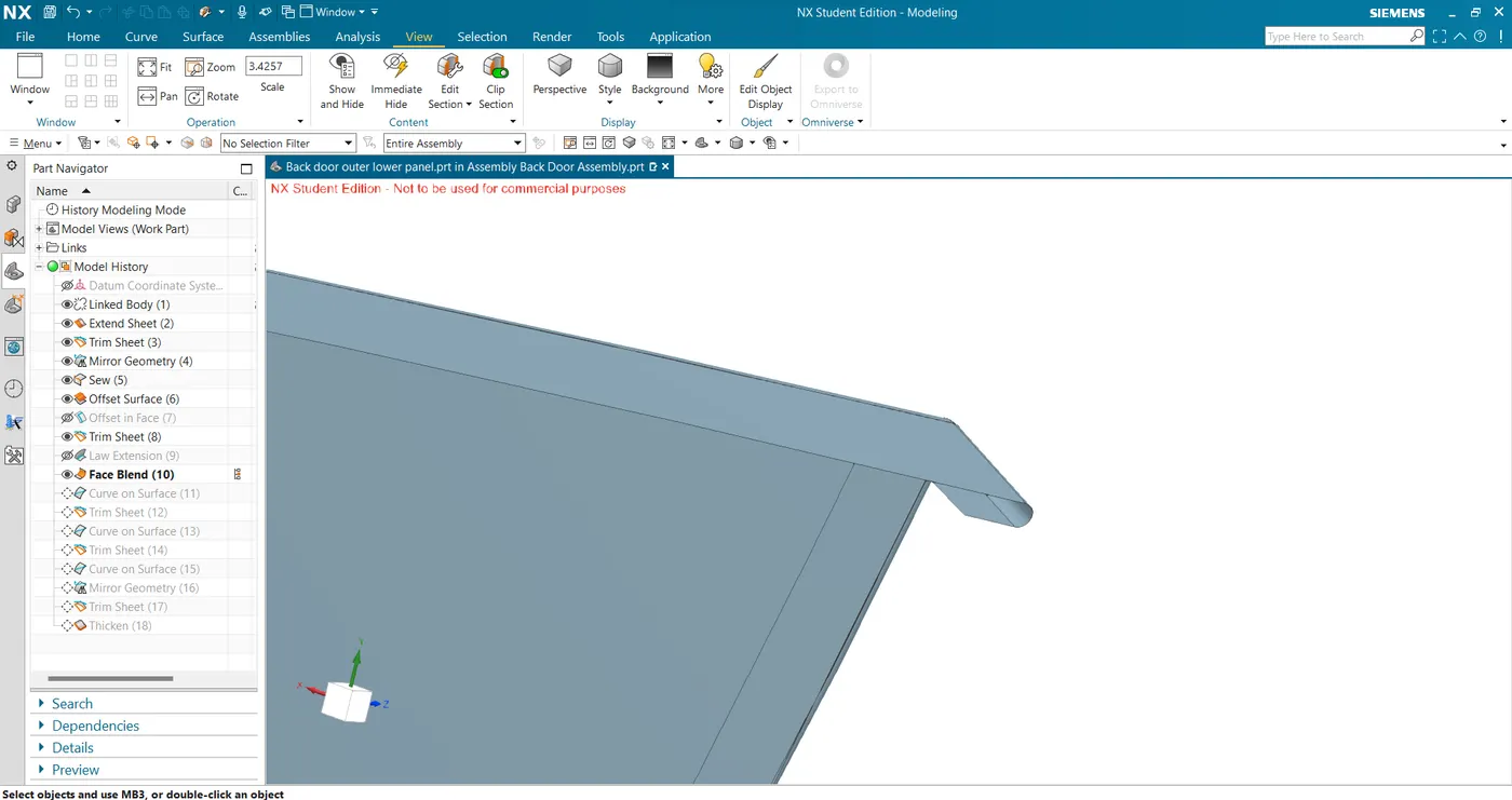
- Next, I operated the three-face blend giving appropriate directions to create the hemming surface.
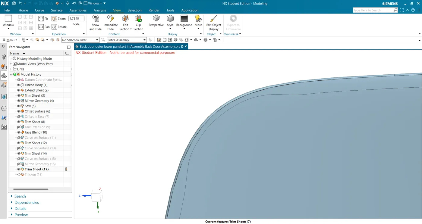
- Later I created reliefs where the bend is sharp and thickened to get the final outer lower part.
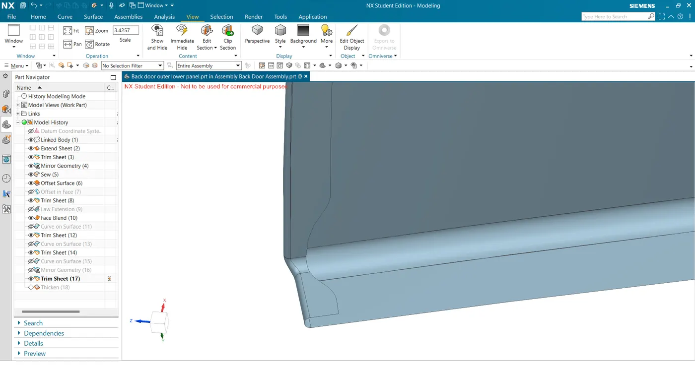
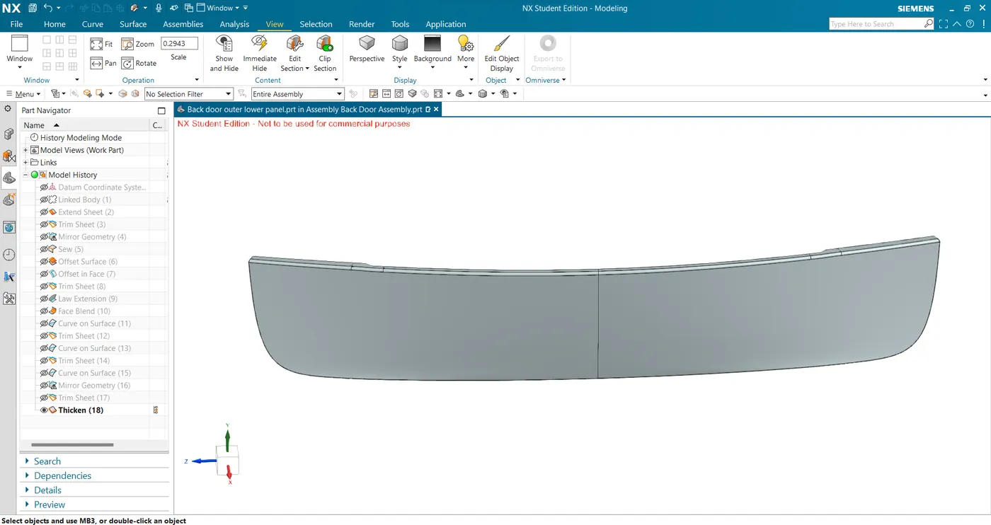
- I created a mirrored geometry of the given A surface and sewed them together to obtain the complete lower outer panel surface.
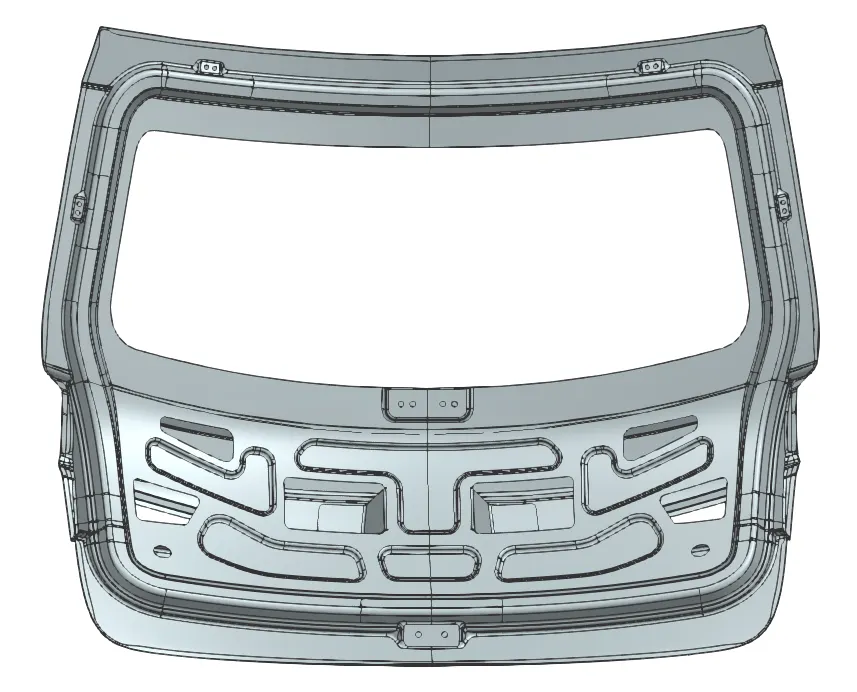
- Inner Panel
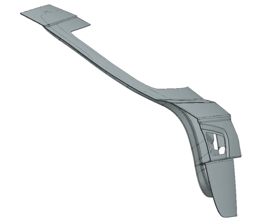
- First, we extract the outer class A surfaces and create a tooling direction using derived lines.
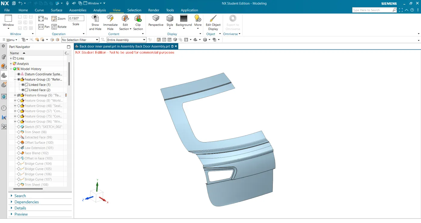
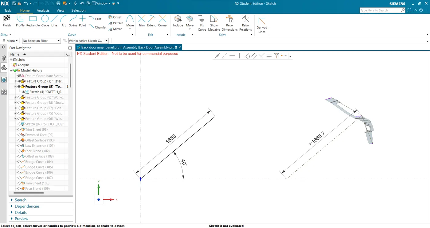
- To create the sealing flange, I started by offsetting the outer upper surface by 1.7mm (0.75+0.2+0.75mm) and later the plane surfaces by 25 mm.
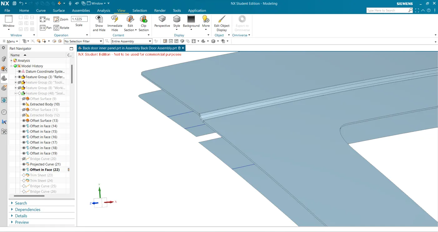
- I then used the offset-in-face command to create the sealing flange base and trim it from the 25mm offset panel.
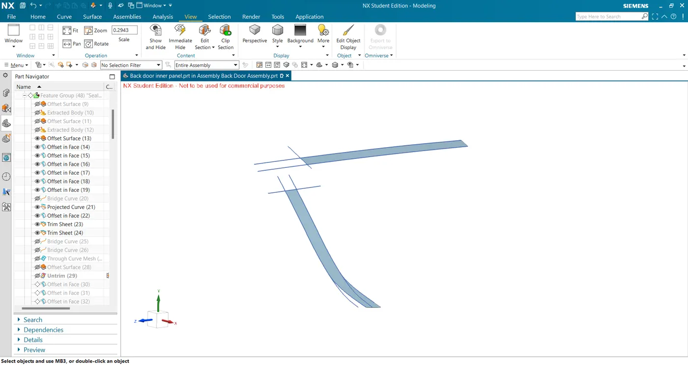
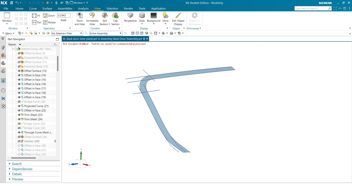
- I then used bridge curves and through curve mesh command connected the above sealing bases to get a surface.
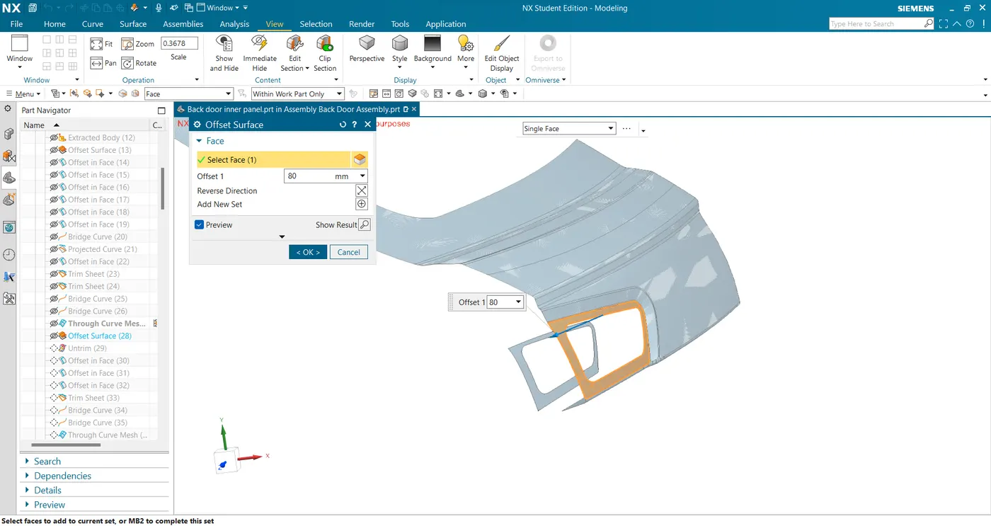
- Next, offset the tail light area for 80mm to align with the sealing surface and untrim it.
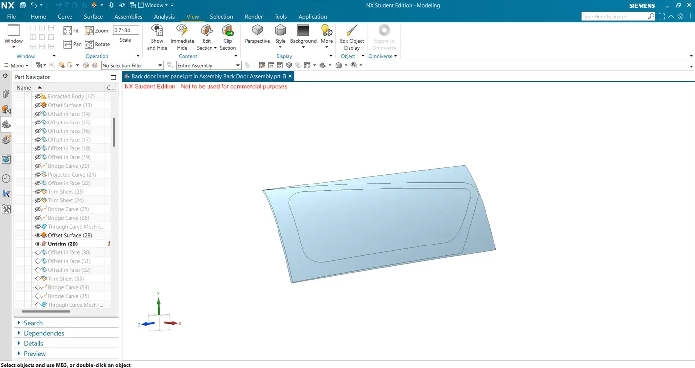
- Next, use the offset curve in face command on this untrimmed surface and trim the plane surface to keep the sealing flange flat.
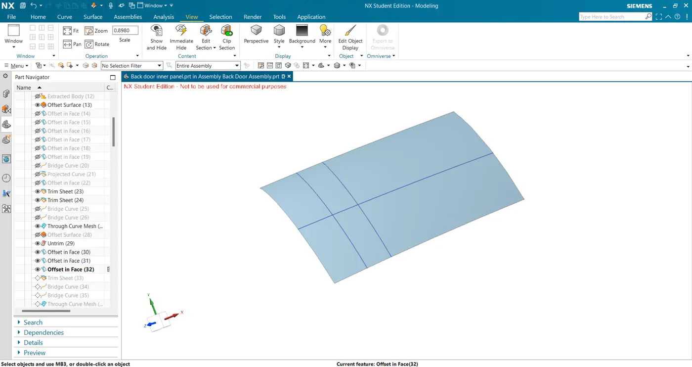
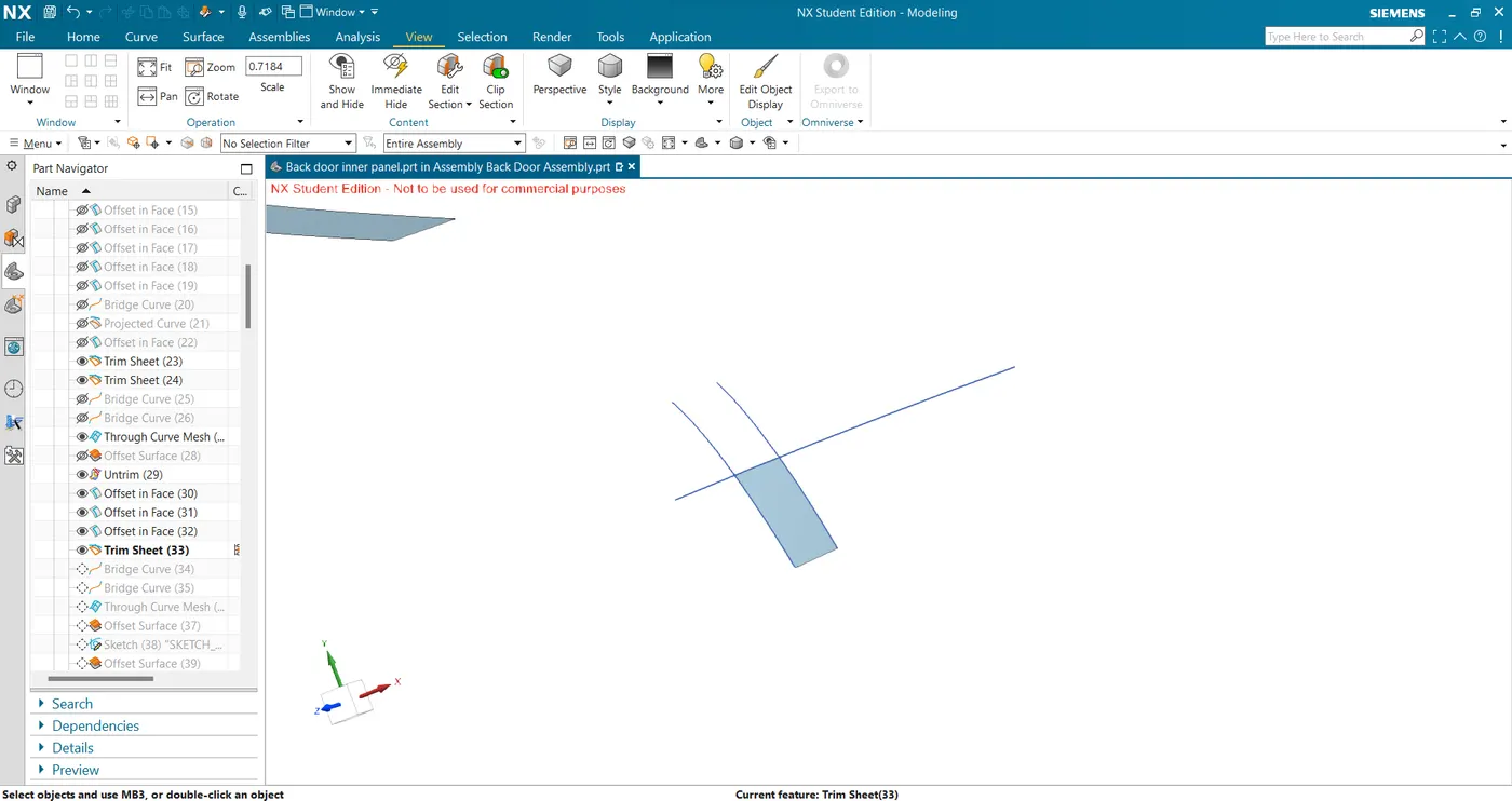
- Now create bridge curves to join with the primary sealing flange and create through curve mesh.
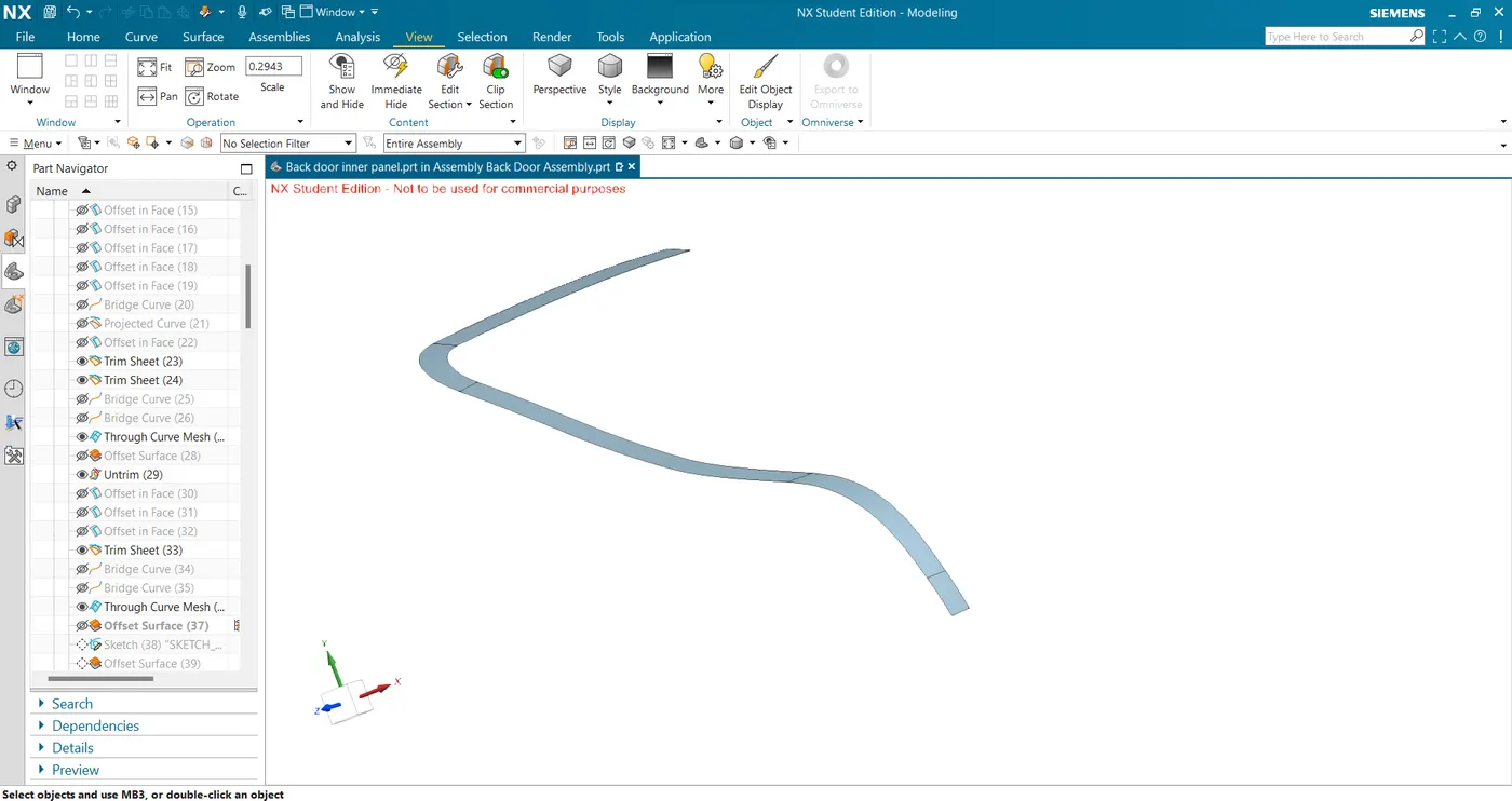
- Next, offset the lower outer surface for 73mm and create a sketch to trim the base of the sealing flange.
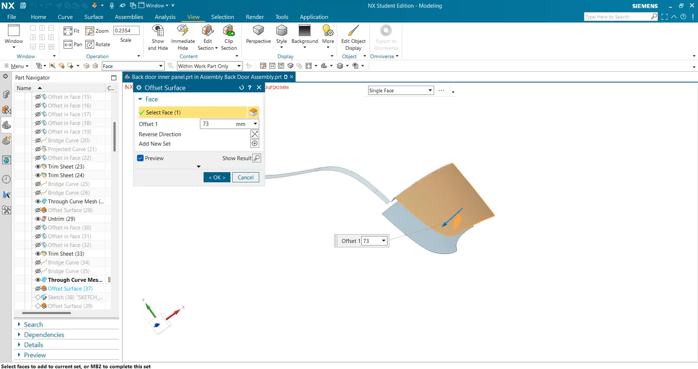
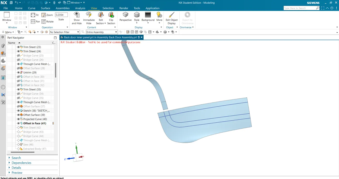
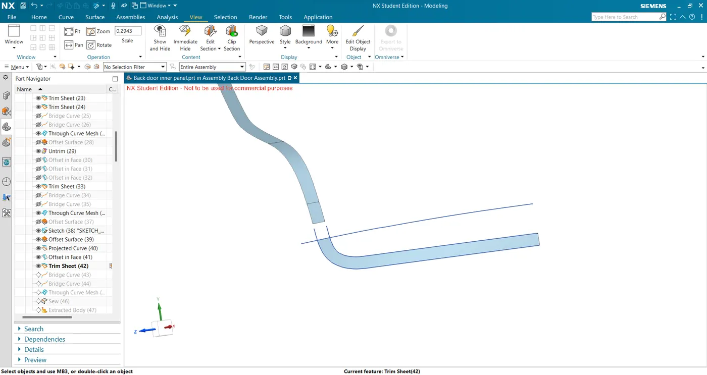
- create bridge curves and create surfaces using through curve mesh and sew all surfaces to get the final sealing base surface.
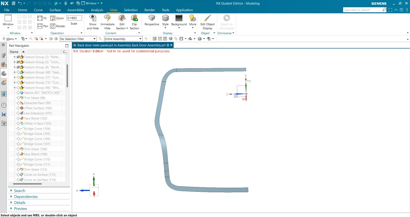
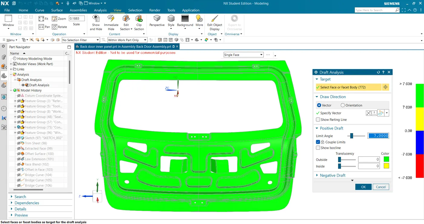
- Then I created the connecting flange using the law extension from the sealing base considering the draft angle of 7 degrees.
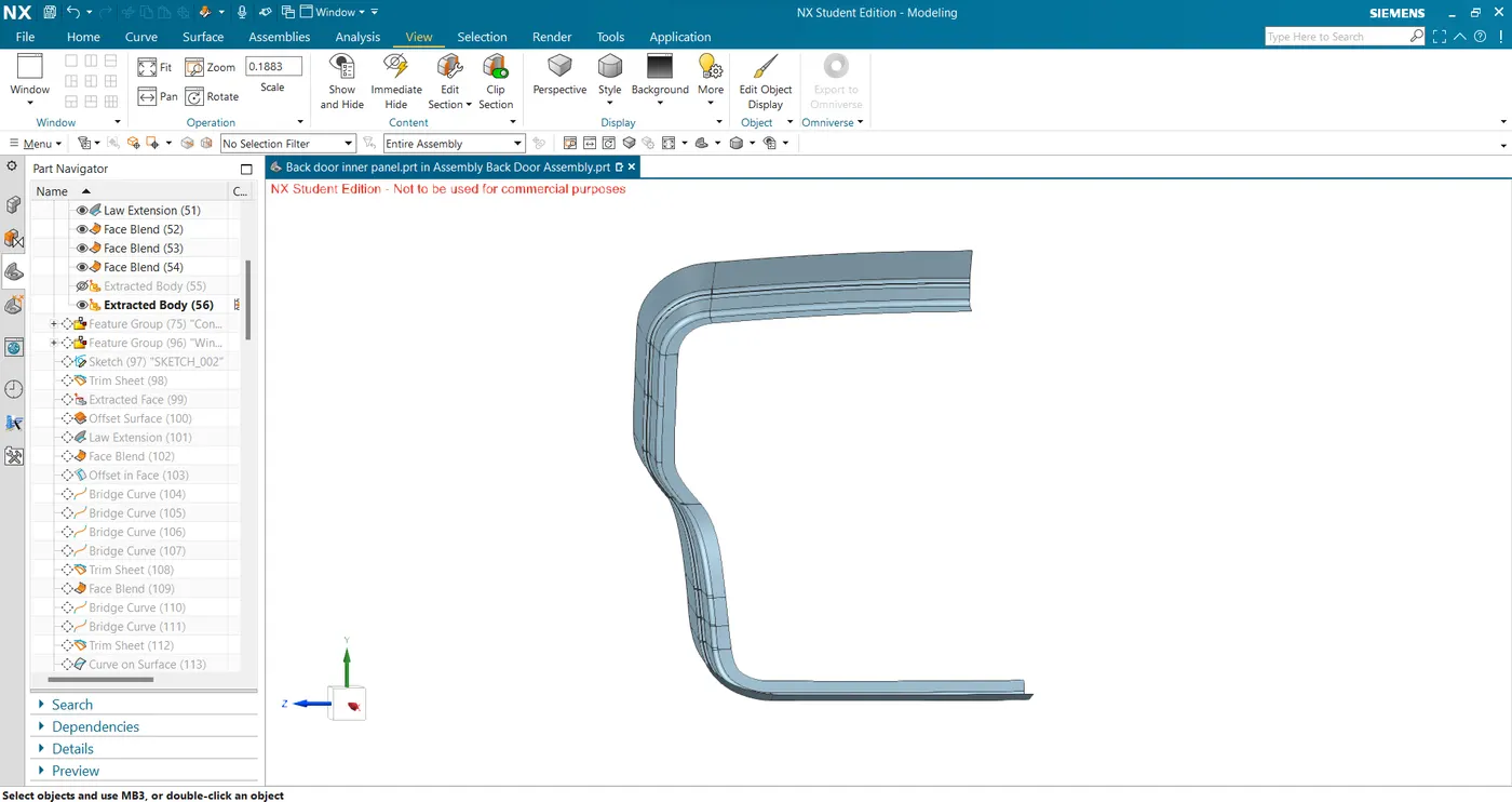
- Trim and extend with the offset outer upper and lower panel to get the outer surface of inner panel.
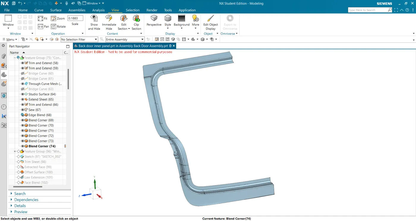
- Extract and extend the windshield area of the offset surface and sew with sealing flange.
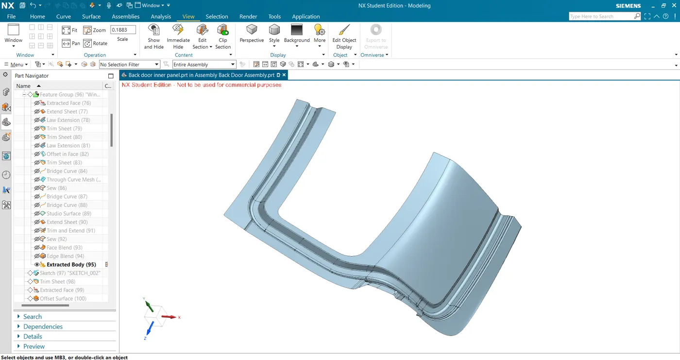
- Create a sketch to make the flange for the mastic location.
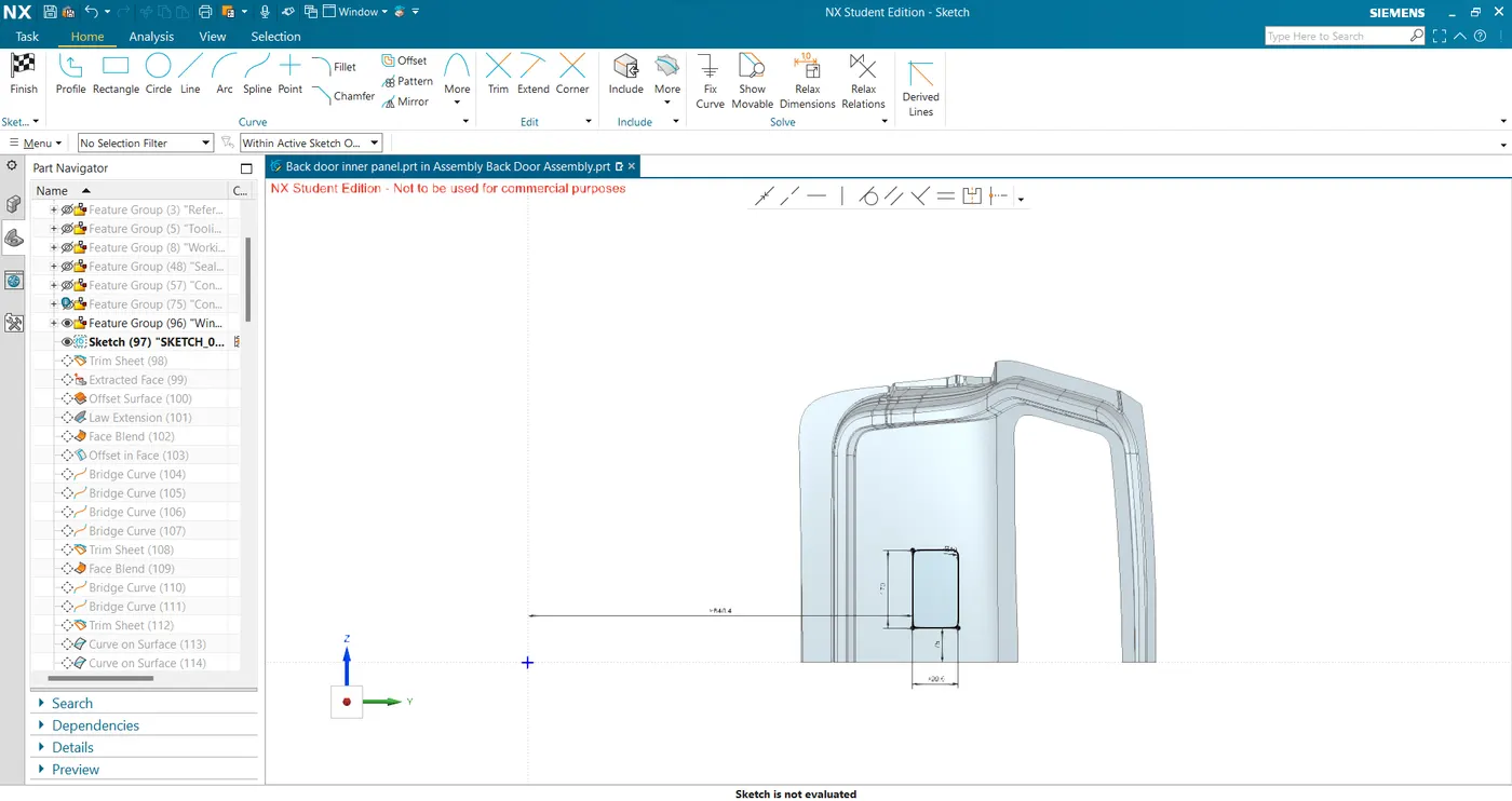
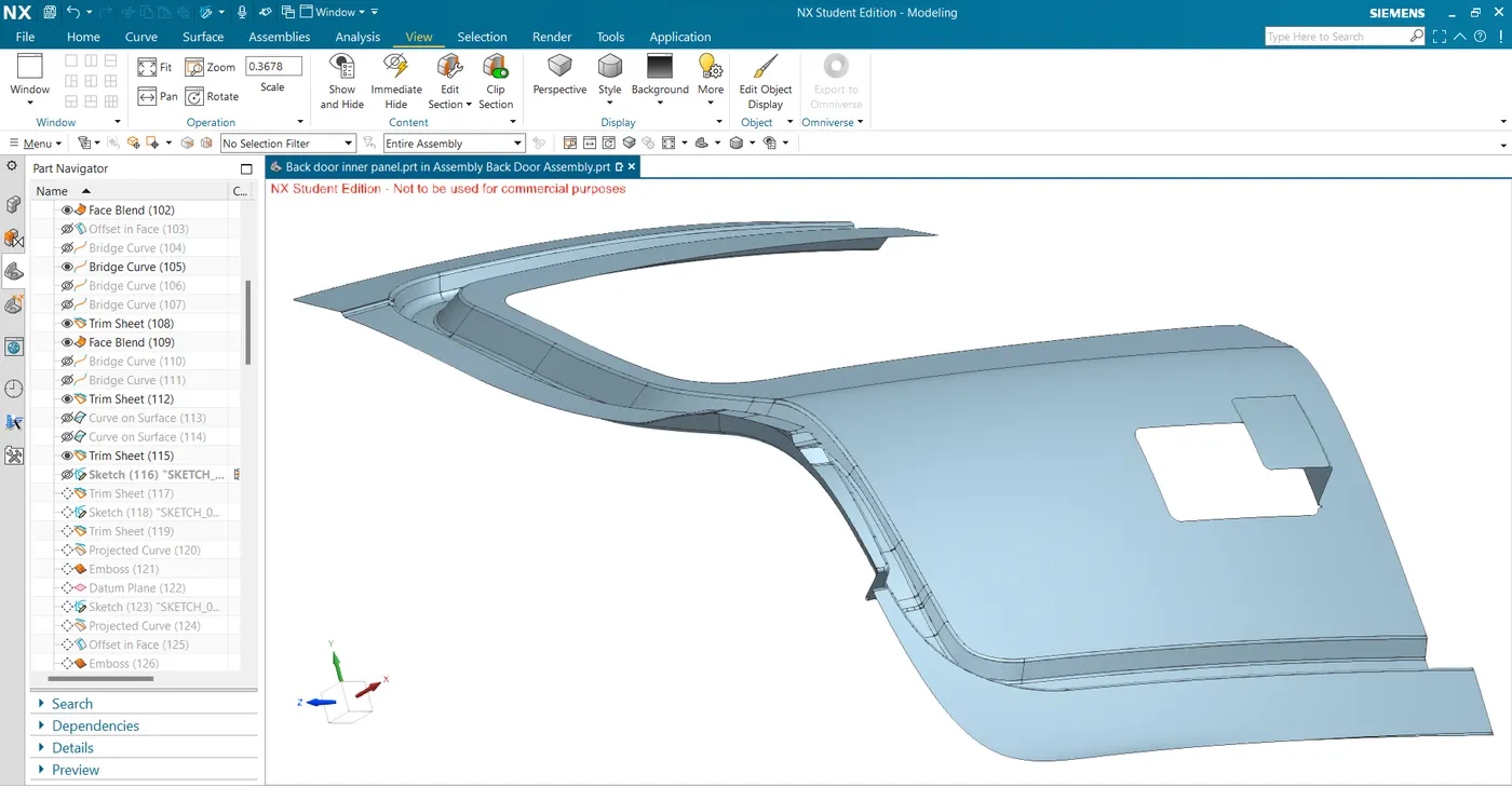
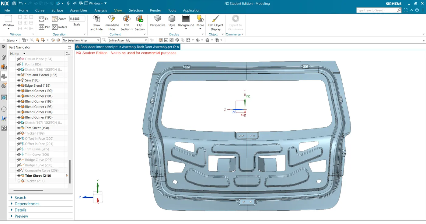
- Next, create a sketch for creating embosses and reinforcement locations to get the final surface after mirroring.
- Draft Analysis -
- First, we extract the outer class A surfaces and create a tooling direction using derived lines.
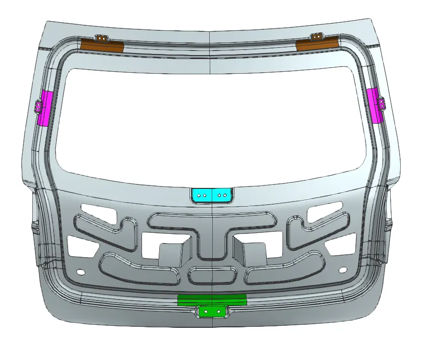
- Hinge Reinforcement
- Make a datum plane at the hinge location and create a line to extrude it to get the hinge mounting surface.
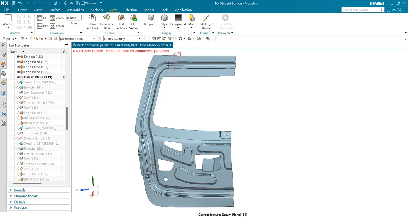
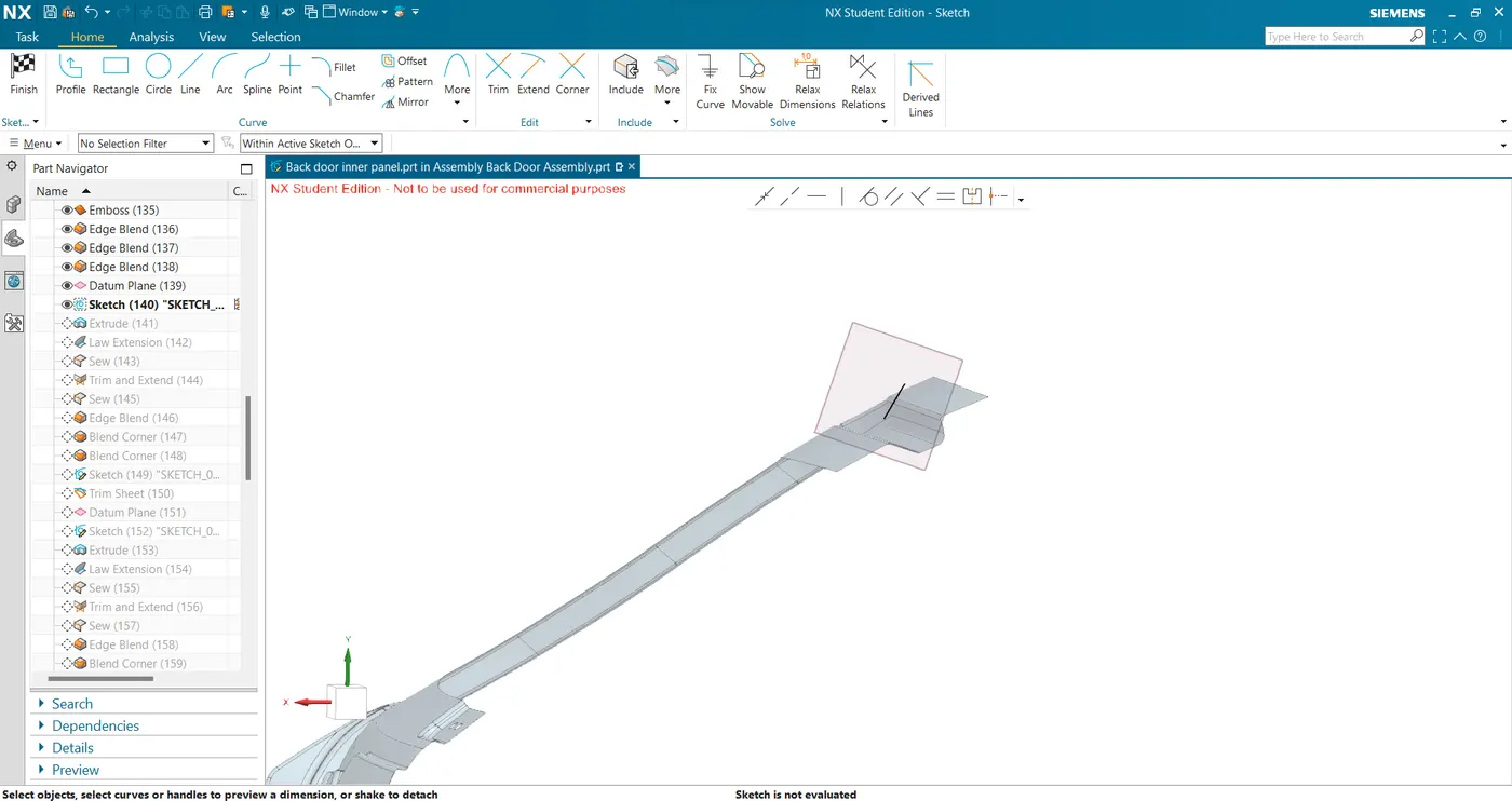
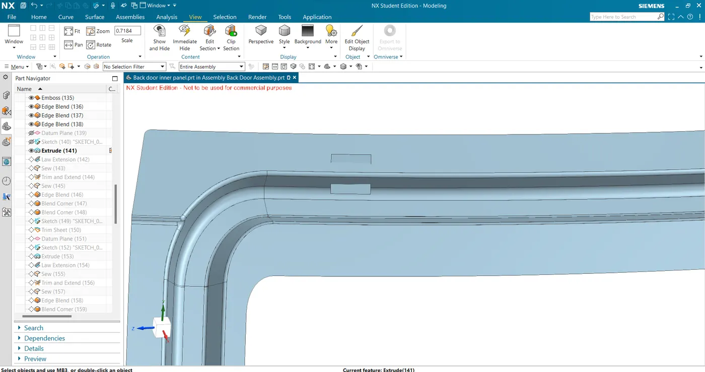
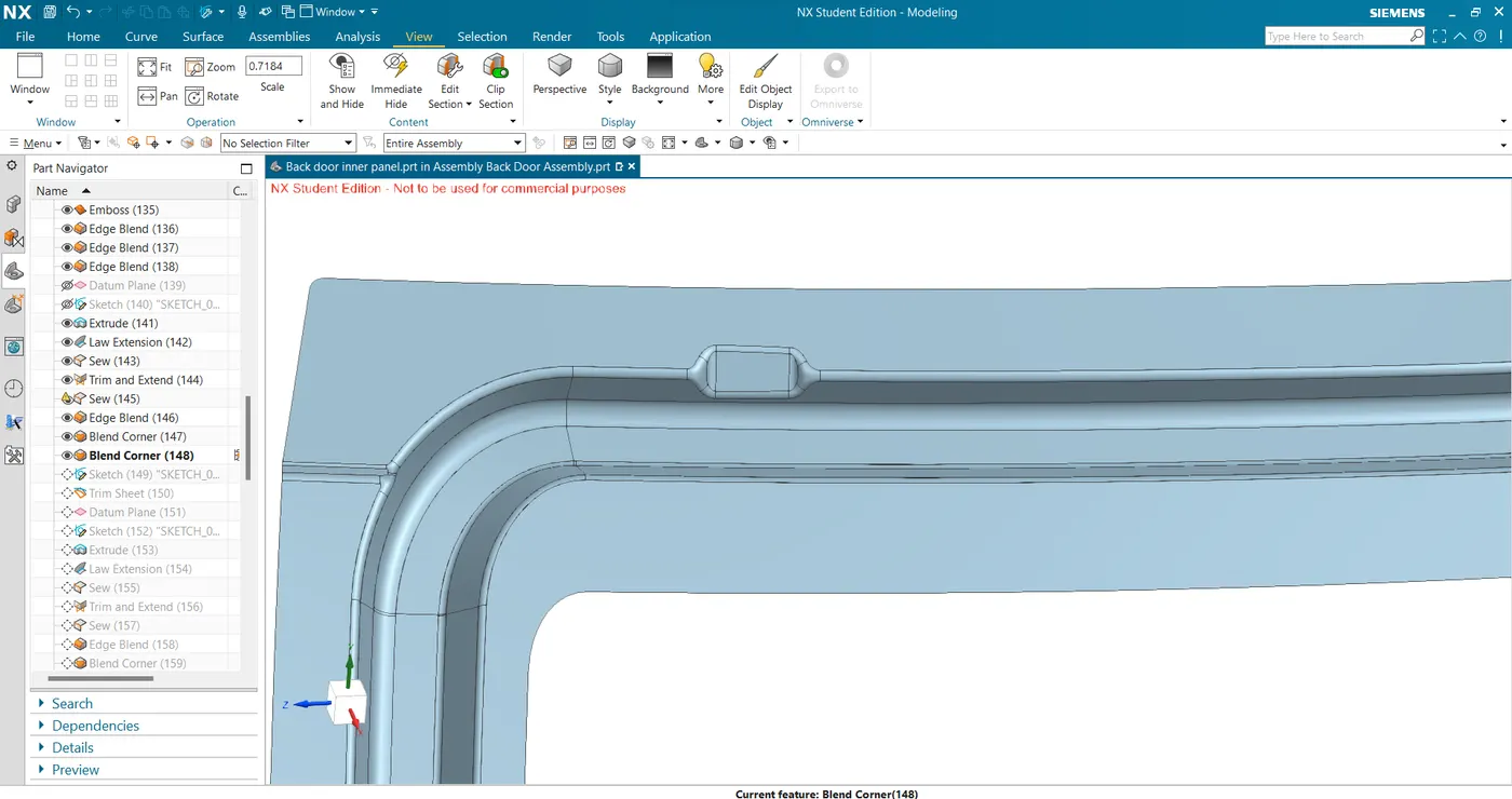
- create law extension and trim and extend with the inner panel to get the final mounting position.
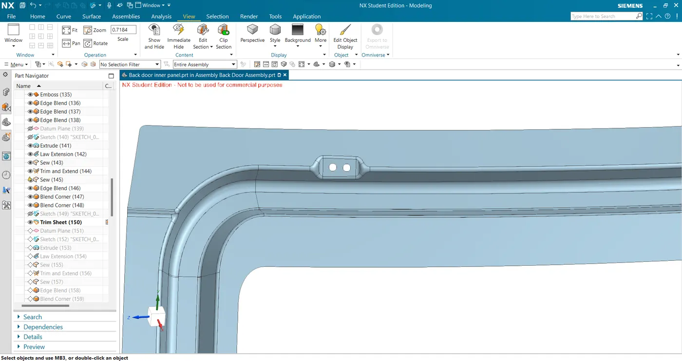
- Sketch the holes and trim to get the final mounting surface.
- Extract the mounting surface and connected sealing surface and trim to get the required length of reinforcement surface.
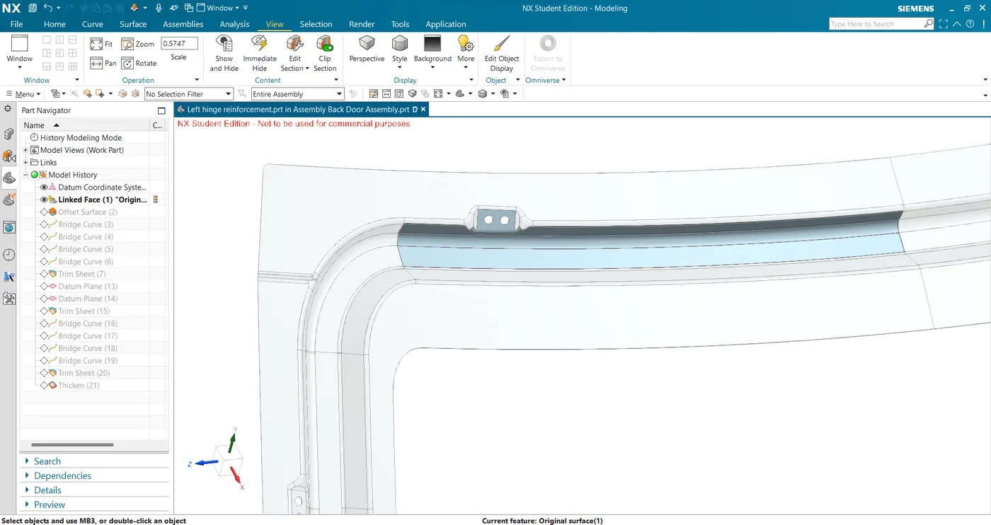
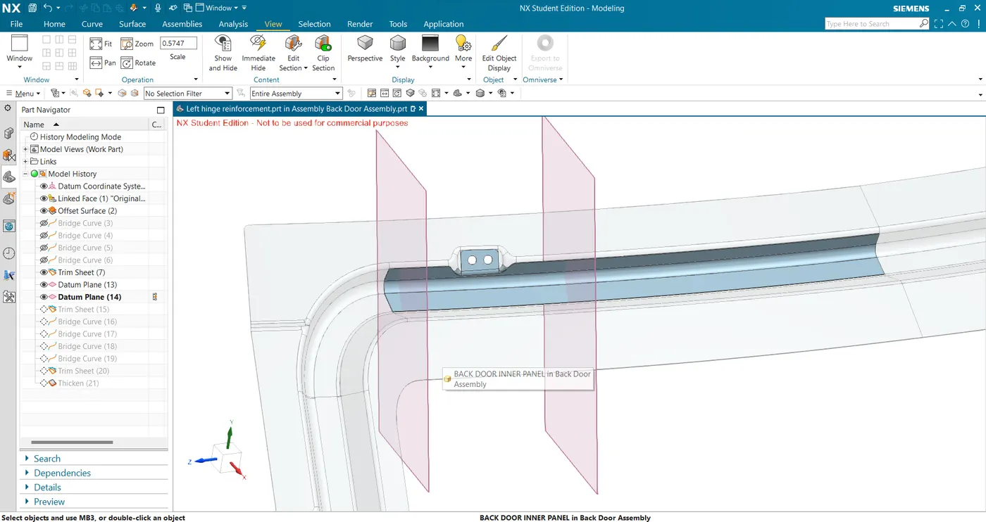
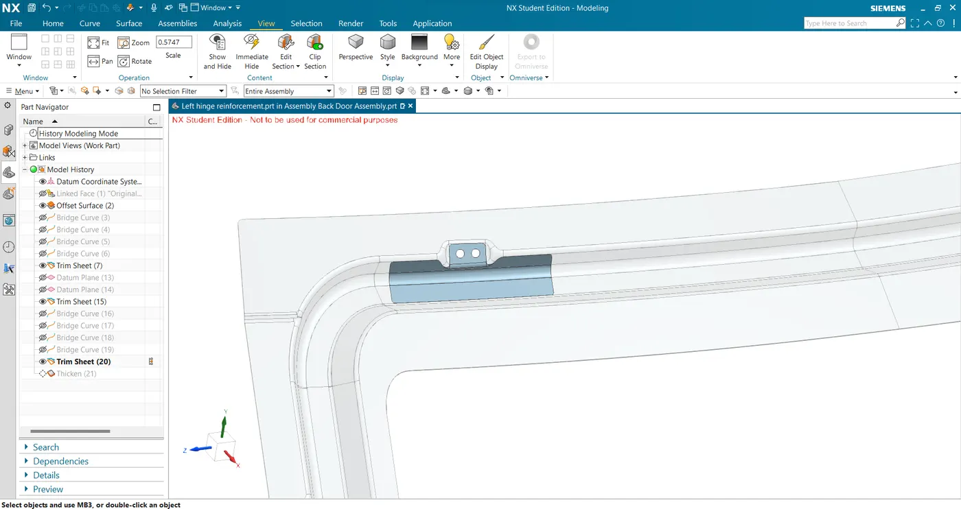
- Thicken for 0.75mm to get the final hinge reinforcement.
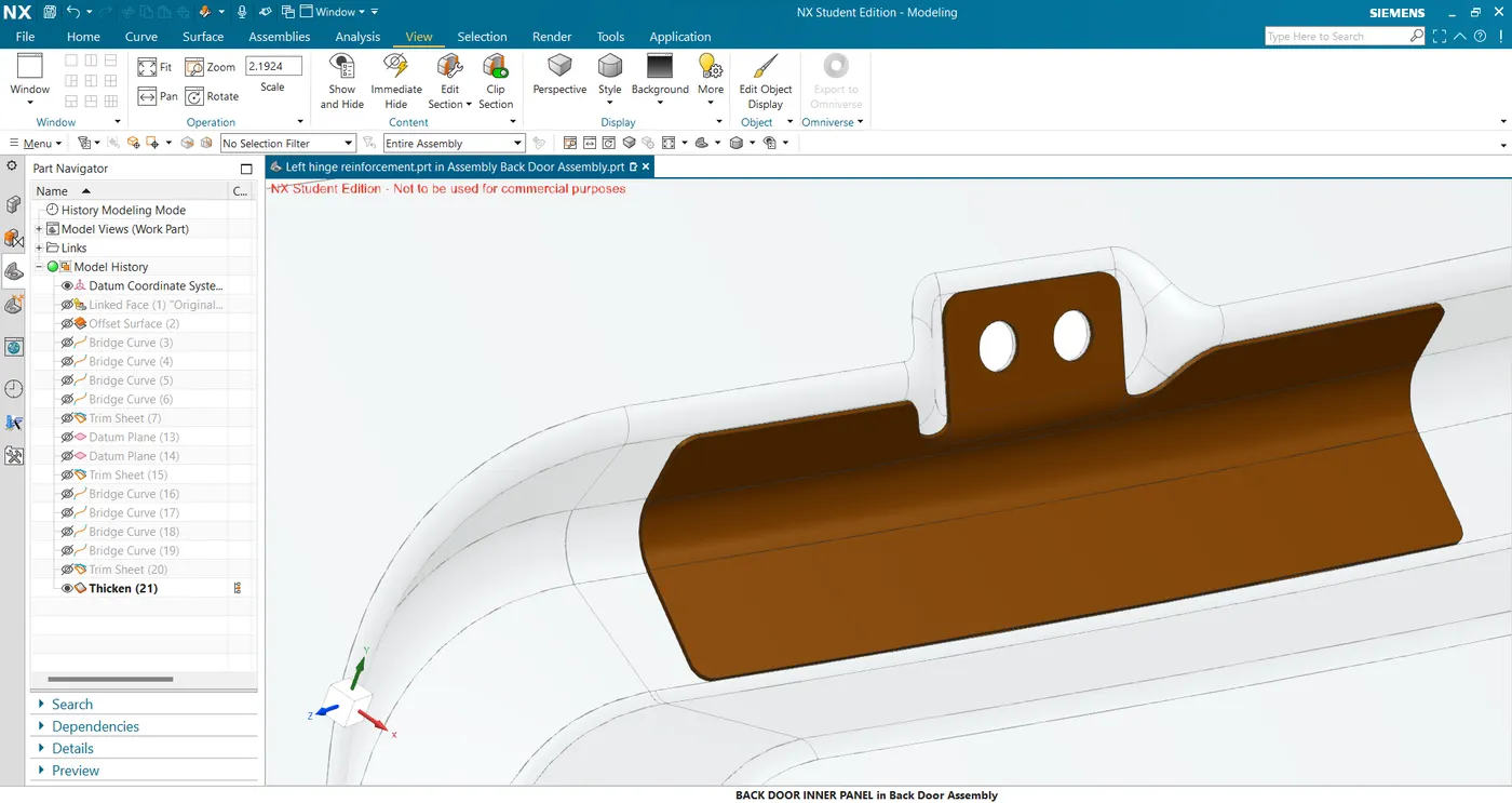
- Make a datum plane at the hinge location and create a line to extrude it to get the hinge mounting surface.
- Gas Stay Reinforcement
- Make a datum plane at the gas stay mounting location and create a line to extrude it to get the mounting surface.
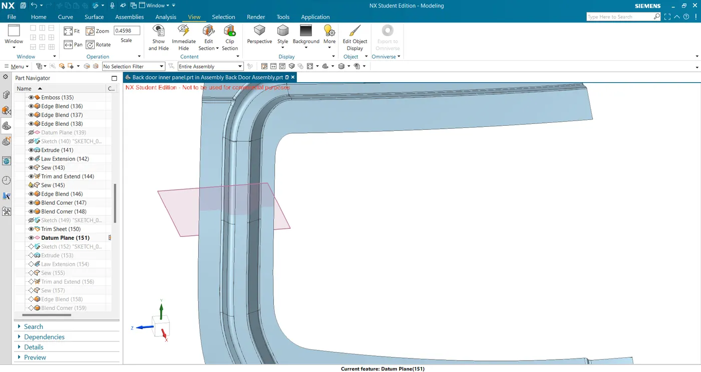
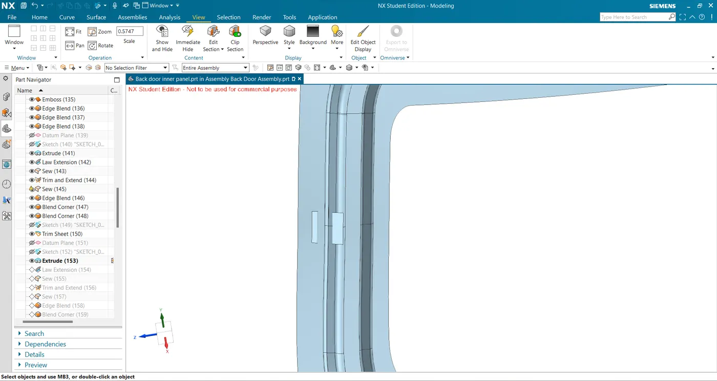
- Create law extension and trim and extend with the inner panel to get the final gas stay mounting surface.
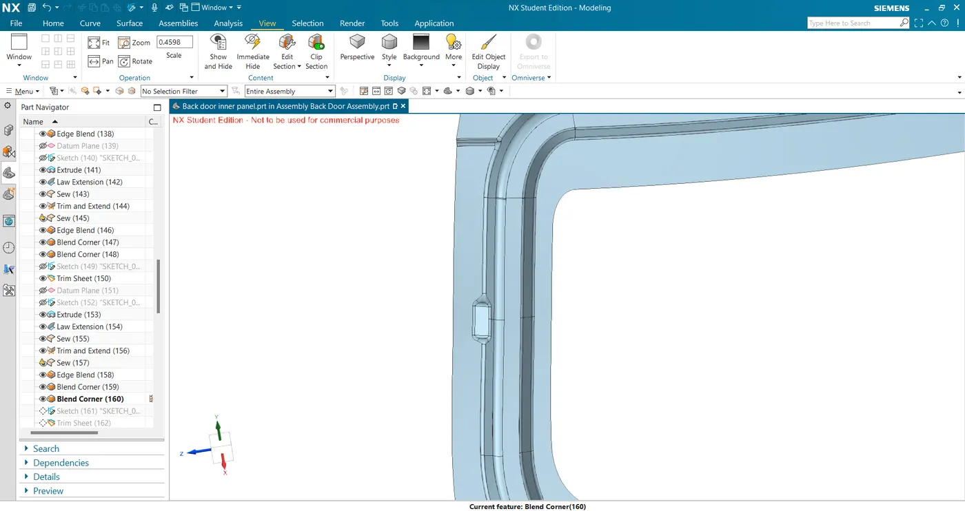
- Sketch the holes and trim to get the final mounting surface.
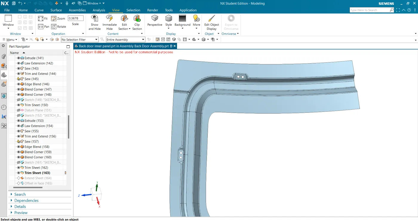
- Extract the mounting surface and connected sealing surface and trim to get the required length of reinforcement surface.
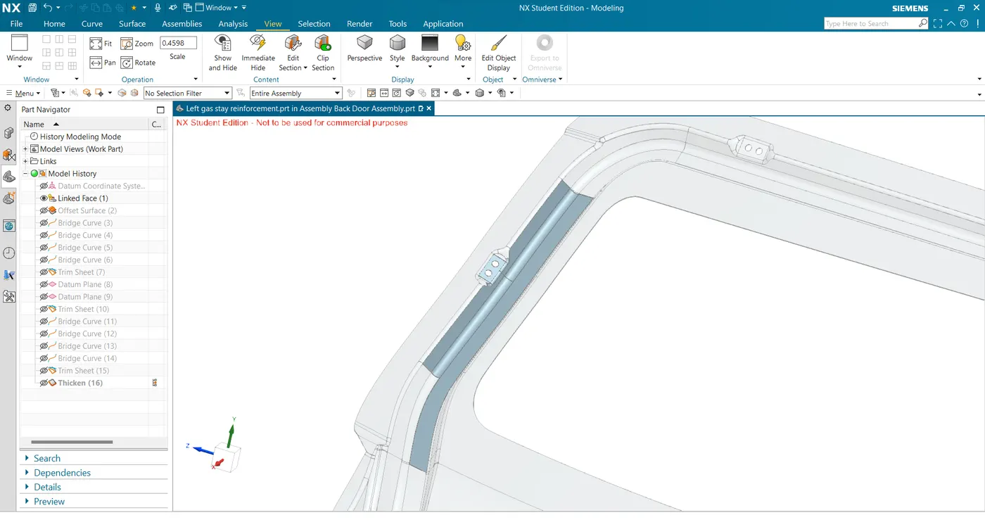
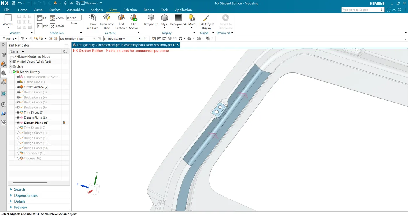
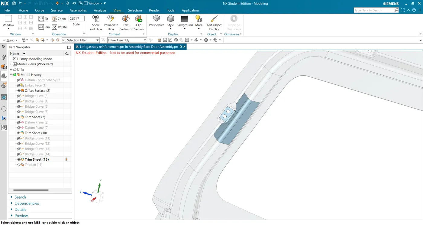
- Thicken for 0.75mm to get the final hinge reinforcement.
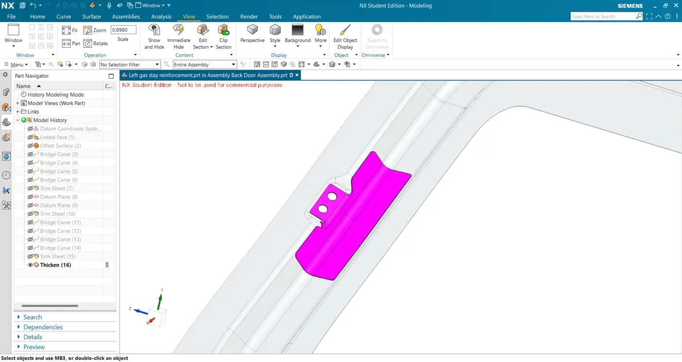
- Make a datum plane at the gas stay mounting location and create a line to extrude it to get the mounting surface.
- Wiper Motor Reinforcement
- Create a sketch for the emboss for wiper motor mounting and using the emboss command create the emboss.
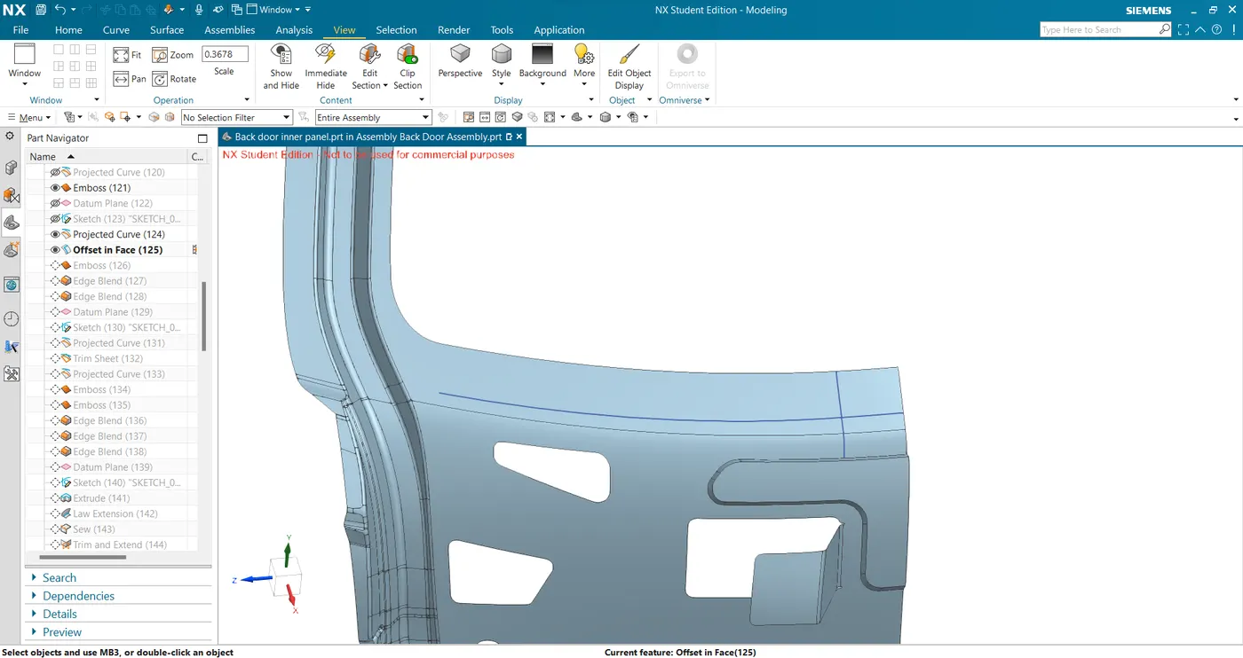
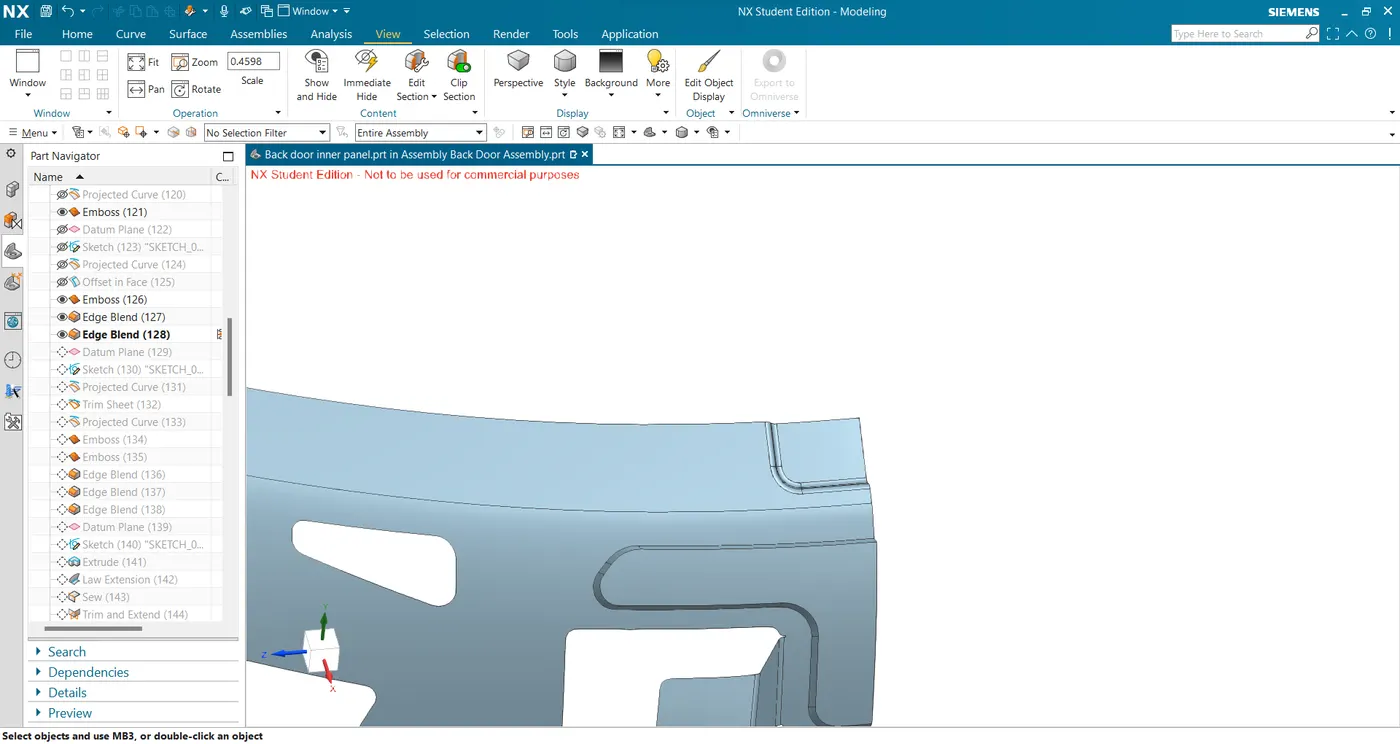
- Again create a sketch for the holes and trim the surface to get the mounting surface.
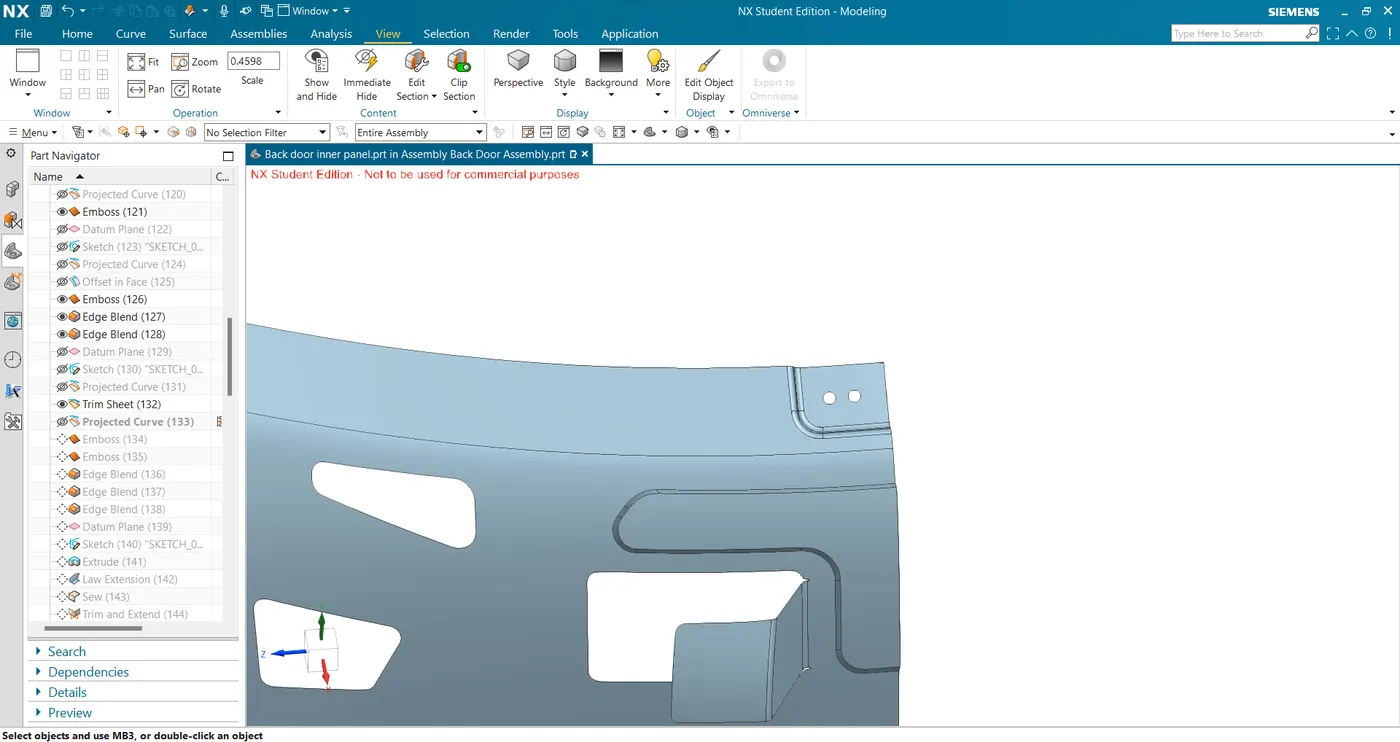
- Extract the mounting surface and offset it by 0.2mm and thicken it for 0.75mm to get the wiper motor reinforcement.
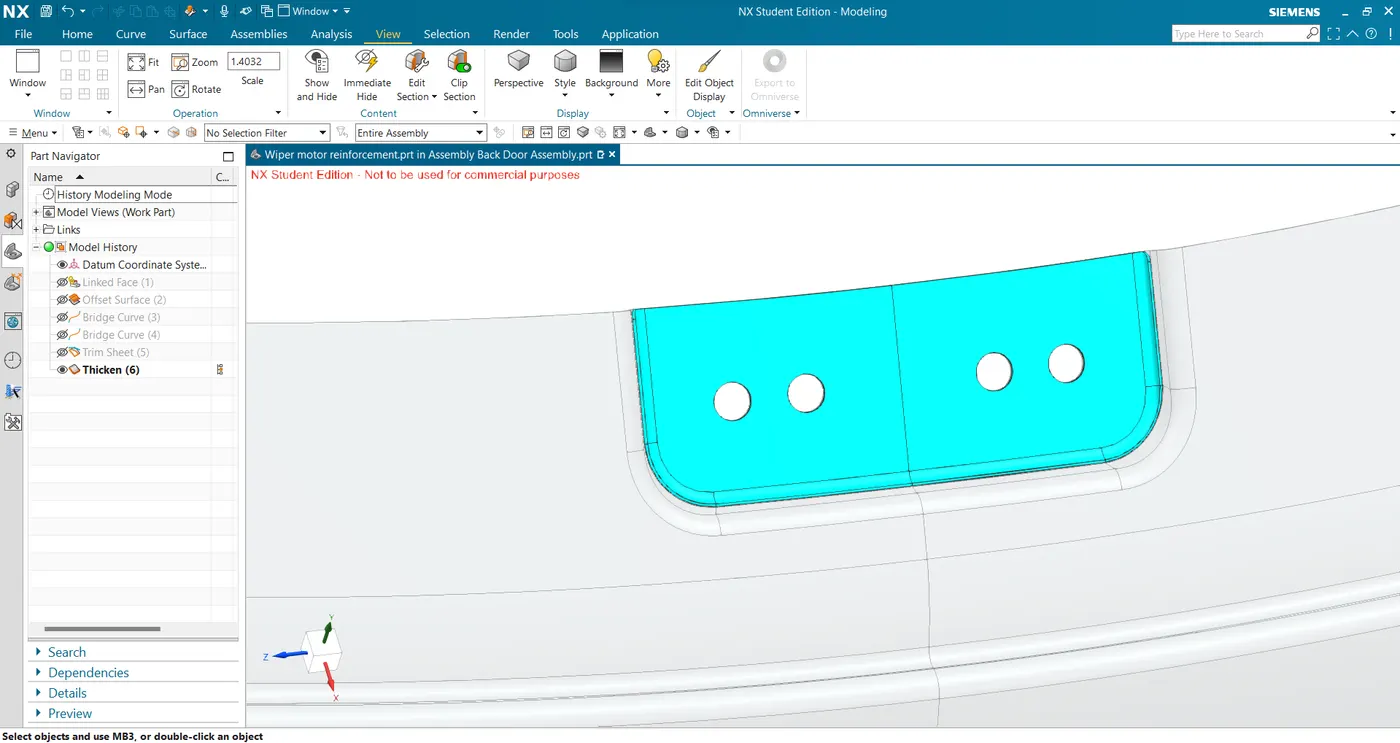
- Create a sketch for the emboss for wiper motor mounting and using the emboss command create the emboss.
- Latch Reinforcement
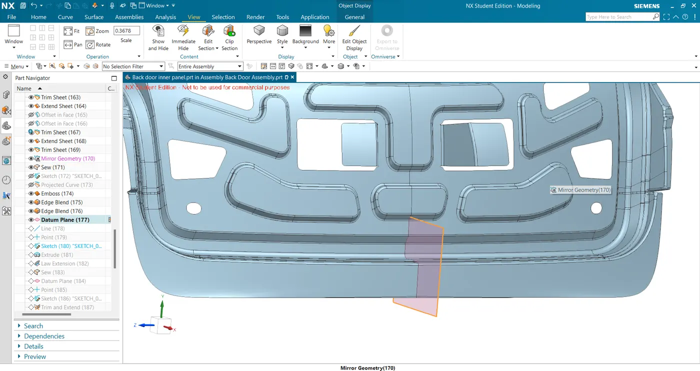
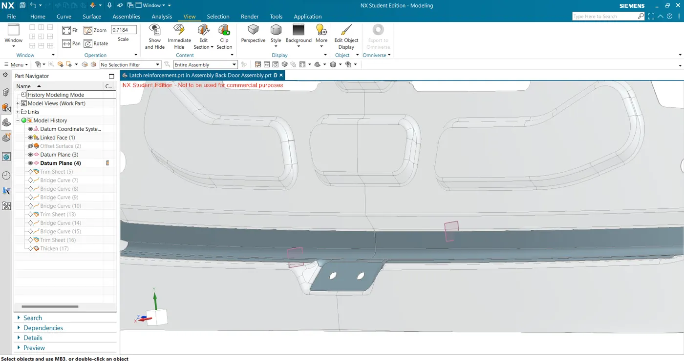
- Create a datum plane at the striker mounting location preferably at the center and sketch a line and extrude for the mounting surface.
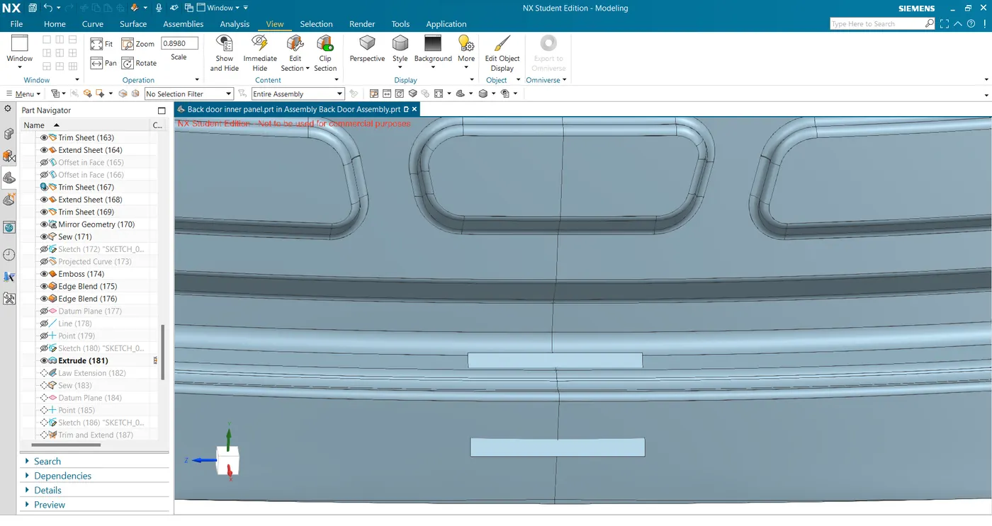
- Create law extension and trim and extend with the inner panel to get the final striker mounting surface.
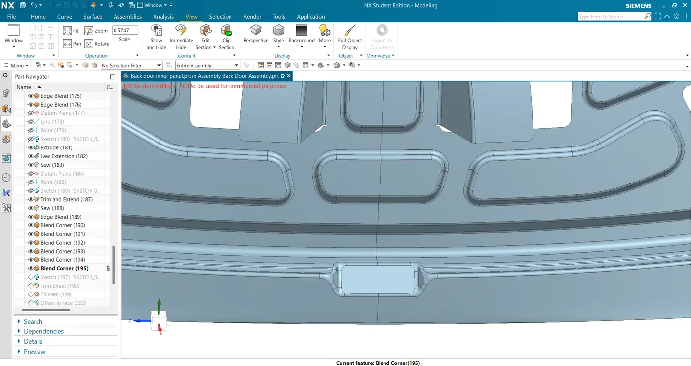
- Sketch the holes and trim to get the final mounting surface.
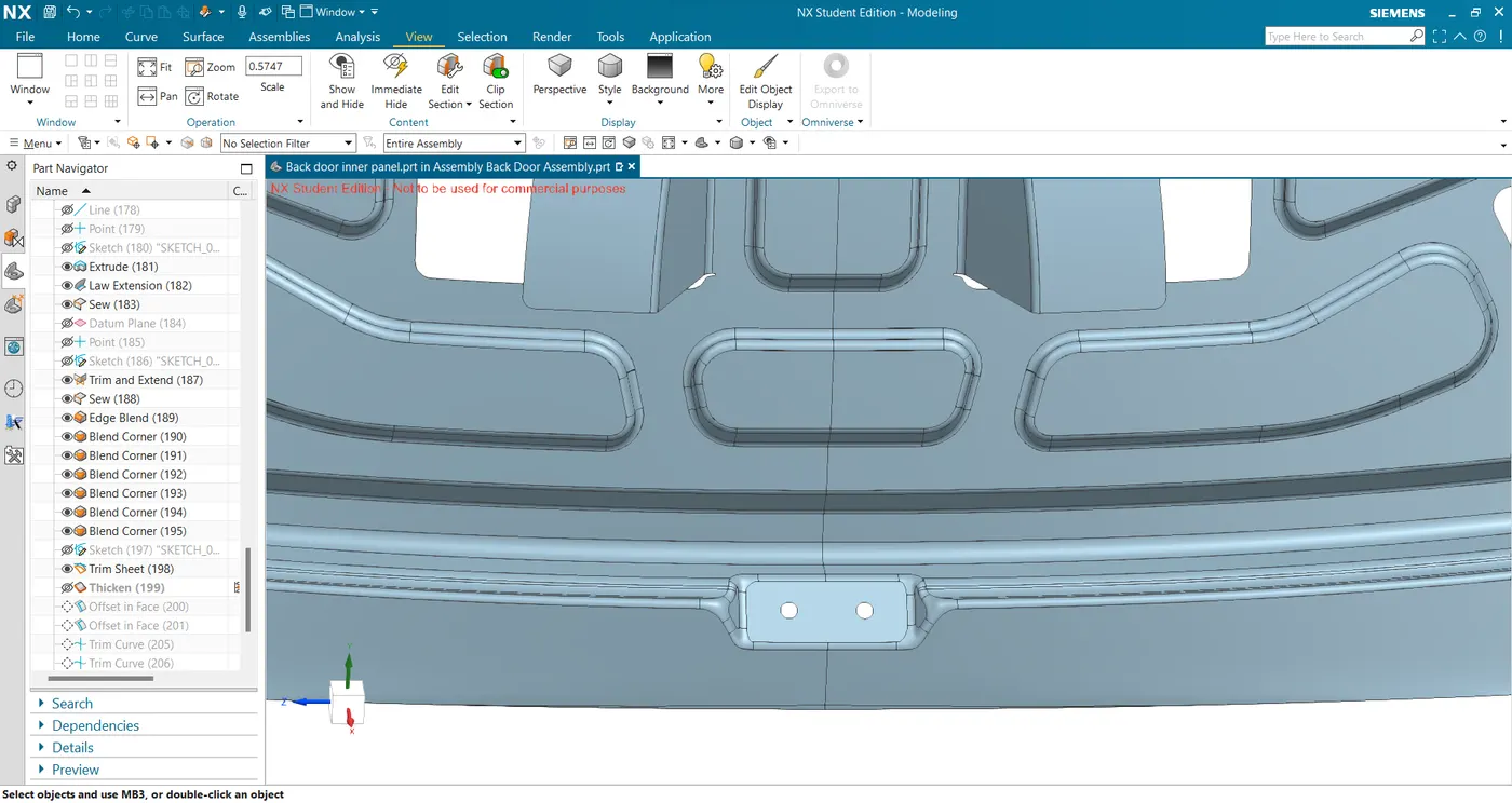
- Extract the mounting surface and connected sealing surface and trim to get the required length of reinforcement surface.
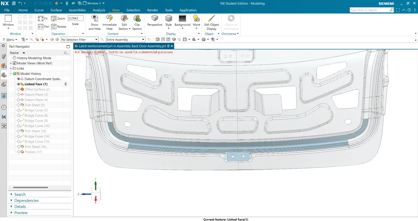
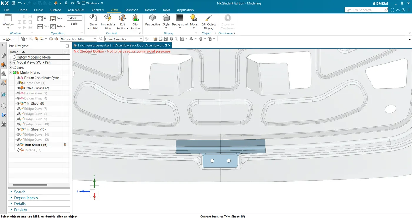
- Thicken for 0.75mm to get the final striker reinforcement.
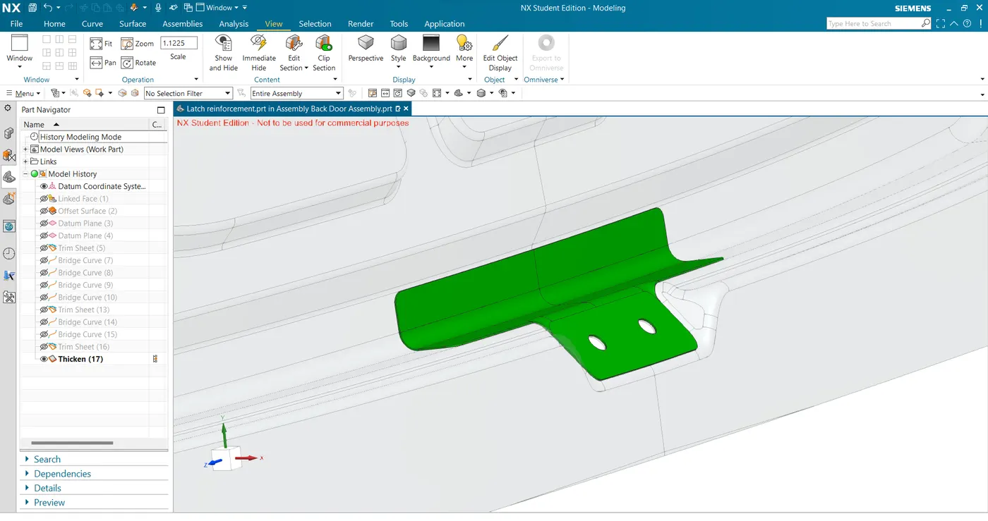
- Create a datum plane at the striker mounting location preferably at the center and sketch a line and extrude for the mounting surface.
3D VIEWS OF BACK DOOR