Design of backdoor
AIM : To Use the provided styling surface to come up with a back door design, and to use appropriate design methodologies, and provide the necessary reinforcements and embosses
BACK DOOR DESIGN
The design considerations of Backdoor are :
- Visibility Criteria
- Force Dissipation
- Latch and Striker Positions
- Hinge Position
- Gas Stay Position
- Hemming and Relief Areas
PARTS OF BACKDOOR
- Back door outer panel (both upper and lower)
- Back door inner panel
- Hinge reinforcements
- Gas stay reinforcements
- Latch and striker reinforcements
- Wiper motor reinforcements
These are the certain tests that are done in back door,not only back door but all components must pass these tests but different components have different test because of the functionality.
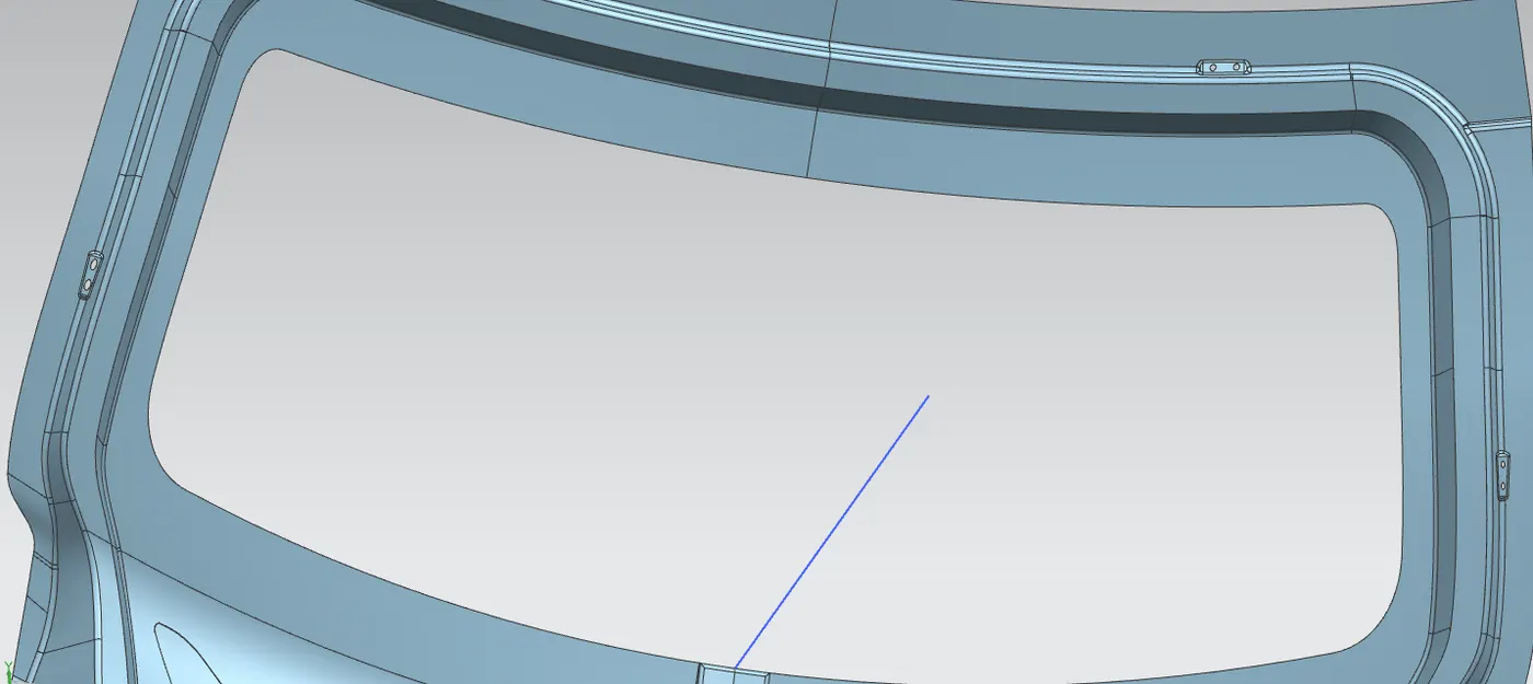
Creation of Tooling Axis Direction :
Create a Line from one end of inner panel to the ege of the windshield region and again create another line from opposite end of the inner panel to the windshied region in such a way
that both these lines intersect at a point . Now Create a line bisecting these two lines which is our required Tooling Axis direction .
Latch Trajecory :
The trajectory is created to position the latch and striker .latch system must be able to catch the striker of the door the while closing. Circle is drawn from the hinge axis.
For positioning the Latch & Stricker, we have to create a trajectory passing through a midpoint of line/ axis connecting two hinge mountings on either sides .The striker follow this path as shown .
Inputs for designing of backdoor:
- Outer Panel - 0.75 mm
- Inner Panel - 0.75 mm
- Reinforcements - 1.5 mm
Hemming :
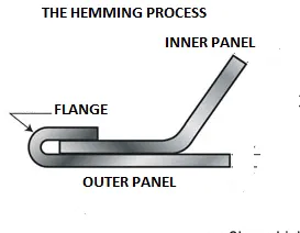
Hems are folds to the edge of a part to be create a rounded ,safe edge . Hems may be open,flat or tear-dropped and tolerances depend on the Hem's radius ,and features near the hems. The process of
creating the hems is called 'Hemming ' .
Hems are created by bending a flange of your part back on itself. This increases the strength of the hemmed edge and also gets rid of any sharp edges, which your technicians (and possibly your future self) will thank you for. The downside (drawback) of hems is that they're expensive (they usually take three bend operations to form) and add weight to your part.
The Heming process involves joining the outer and inner panels of the part by bending their corner curvature areas to 180 degrees. There is also some corner relief given to the sheet to get stationed so that the rollers that do the Heming of sheets can roll appropriately in the required area. Hemming is a sheet metal operation widely used in the automobile sector because the welding or joining process can not be done on styling parts as it may affect the car's aesthetics.
In car part production, hemming is used in assembly as a secondary operation after deep drawing, trimming and flanging operations to join two sheet metal parts (outer and inner) together. Typical parts for this type of assembly are hoods, doors, trunk lids and fenders.
Draft Analysis :
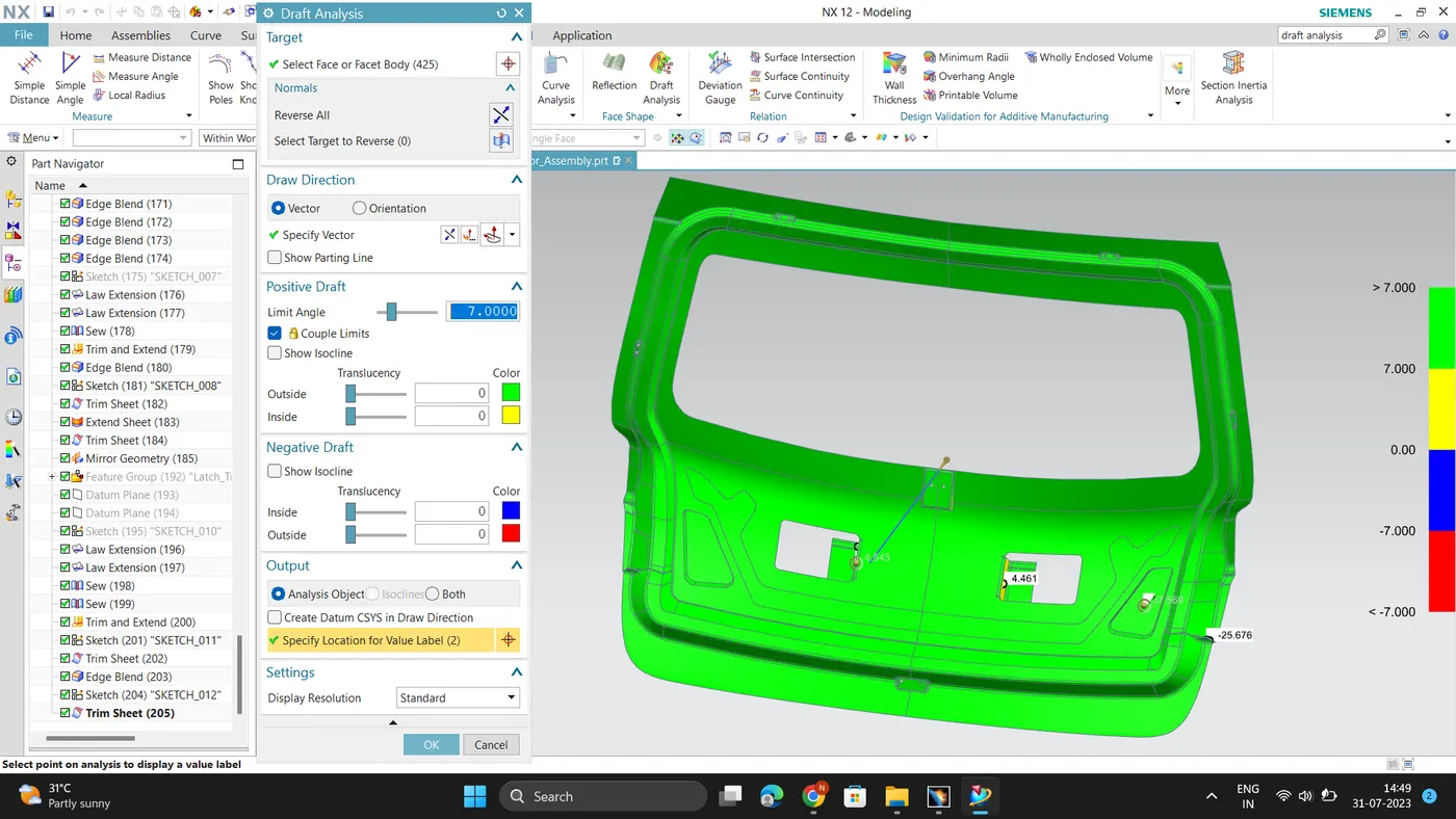
Draft Analysis Tool is used to check the correct application of draft to each and every faces of the component .
No parts can be ejected from the Tool if it is having straight 90 degrees profile from its Base surface .
Hence, a specific draft angle is provided to each and every area of the component in order to remove it from the tool/die
without damaging the workpiece .
Here, we are providing the direction(Tooling Axis ) through which the components should eject in order to get an easy removal of the components from the tool ,i.e the draft angle of the component through Tooling Axis direction can be known at all places with Draft Analysis Tool .
The Draft Analysis Command can be found in " Analysis " Tab or Make use of " Find a command " tool to search .
Go to Analysis tab------>Face shape group-----> Draft Analysis
(or) Menu------>Analysis------->shape------->Draft Analysis
Go to Draft Analysis under Analysis Tab , First click on the 'vector' option under draw direction as Tooling Axis direction and then select the entire sheet body .
Before Reinforcements
- You can also Know the Draft angle at any location of the component by going through the " OUTPUT " section in Draft Analysis Window
and select the "Specify Location for value label " and now click on the component where you want to know the draft angle .
After Reinforcements
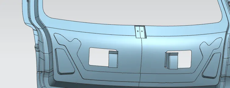
Embosses
Reinforcements :
- Hinge Mounting
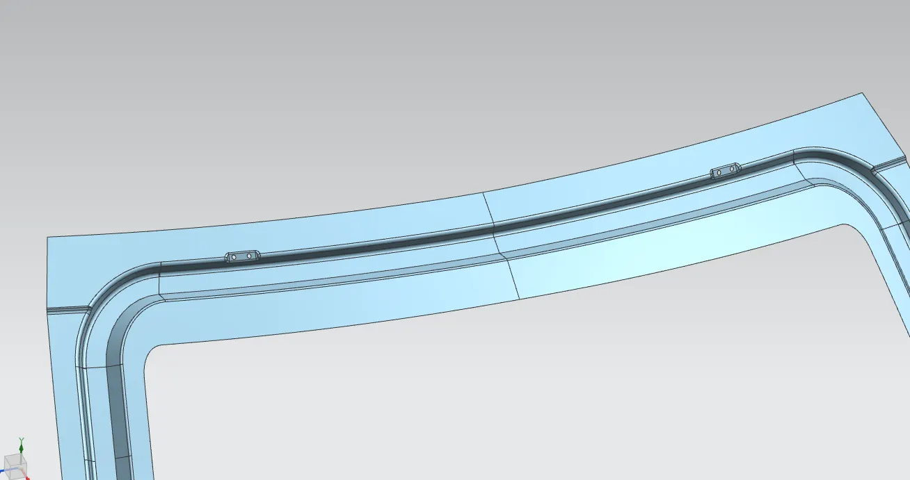
- Gas Stay Mounting
- Wiper Mounting
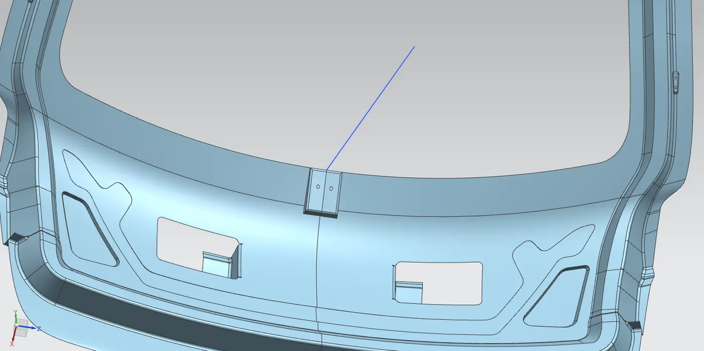
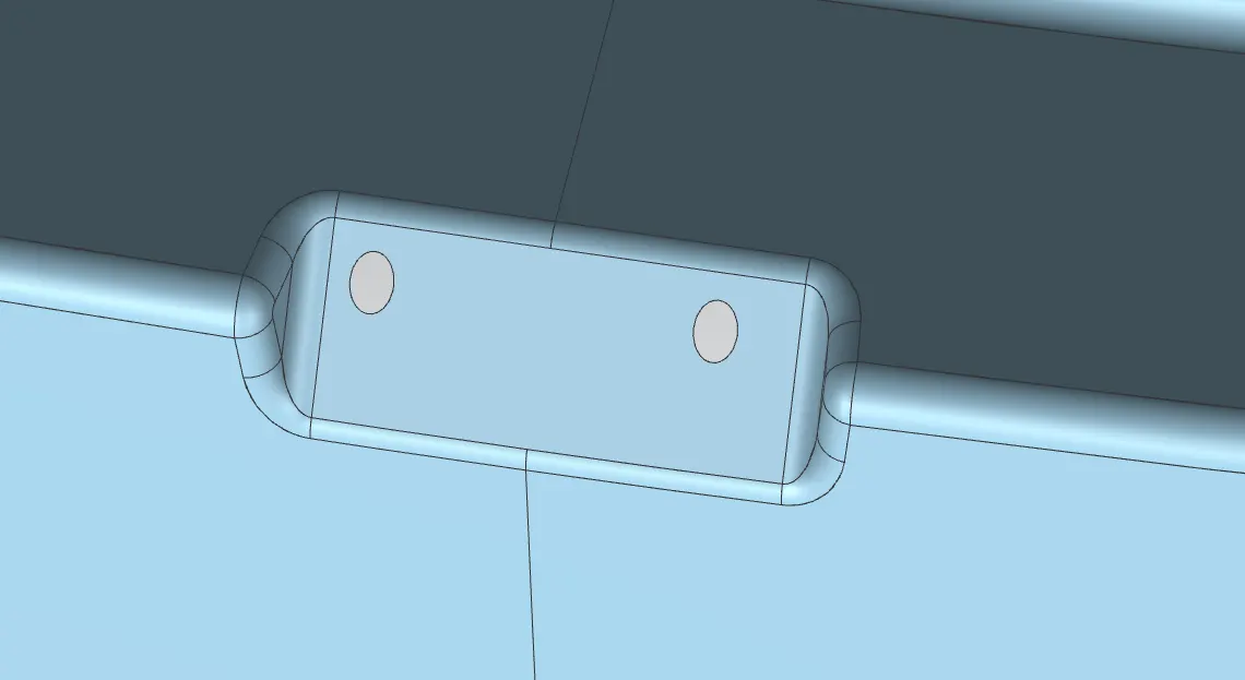
- Latch & Striker Mounting
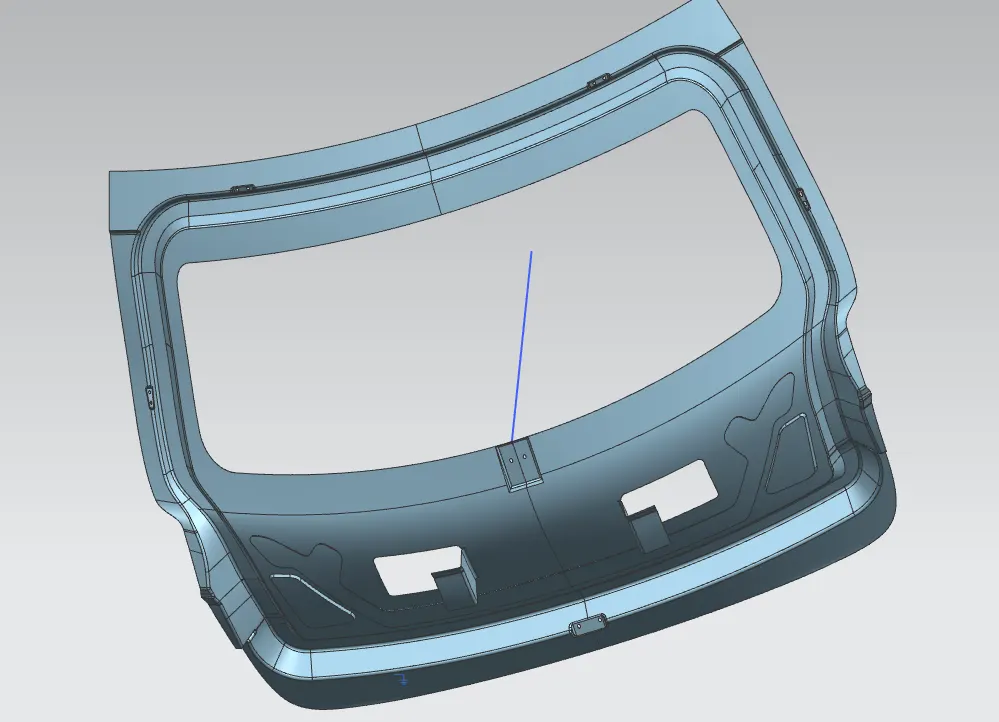
- Backdoor with Reinforcements
- Manufacturing techniques : The various Manufacturing Techniques are
1) Stamping :
The working Components are the punch and die, which perform the cutting operation. They are attached to the upper and lower portions of the die set, respectively called the punch holder(or upper shoe) and
die holder (lower shoe). The die set also includes guide pins and bushings to ensure proper alignment between the punch and die during the stamping operation. The die holder is attached to the base of the press, and the punch holder is attached to the ram. Actuation of the ram accomplishes the pressworking operation.
In addition to these components, a die used for blanking or hole-punching must include a means of preventing the sheet metal from sticking to the punch when it is retracted upward
after the operation. The newly created hole in the stock is the same size as the punch, and it tends to cling to the punch on its withdrawal. The device in the die that strips the sheet metal
from the punch is called a stripper. It is often a simple plate attached to the die with a hole slightly larger than the punch diameter.
For dies that process strips or coils of sheetmetal, a deviceis required to stop the sheet metal as it advances through the die between press cycles. That device is called a stop.
Stops range from simple solid pins located in the path of the strip to block its forward motion, to more complex mechanisms synchronized to rise and retract with the actuation of
the press.
2)Embossing :
Embossing is a forming operation used to create indentations in the sheet, such as raised (or indented) lettering or strengthening ribs . Some stretching and thinning of the metal are involved. This operation may seem similar to coining. However, embossing dies possess matching cavity contours, the punch containing the positive contour and the die containing the negative; whereas coining dies may have quite different cavities in the two die halves, thus causing more significant metal deformation than embossing.
3) Bending:
Bending in sheet-metal work is defined as the straining of the metal around a straight axis . During the bending operation, the metal on the inside of the neutral plane is
compressed, while the metal on the outside of the neutral plane is stretched. The metal is plastically deformed so that the bend
takes a permanent set upon removal of the stresses that caused it. Bending produces little or no change in the thickness of the sheet metal.
Bending operations are performed using punch and die tooling. The two common bending methods and associated tooling are V-bending, performed with a V-die; and
edge bending, performed with a wiping die.
In V-bending, the sheet metal is bent between a V-shaped punch and die. Included angles ranging from very obtuse to very acute can be made with V-dies.
V-bending is generally used for low-production operations. It is often performed on a press brake and the associated V-dies are relatively simple and inexpensive.
Edge bending involves cantilever loading of the sheet metal. A pressure pad is used to apply a force to hold the base of the part against the die, while the punch forces the
part to yield and bend over the edge of the die. In the setup edge bending is limited to bends of 90degrees or less. More complicated wiping dies can be
designed for bend angles greater than 90degrees. Because of the pressure pad, wiping dies are more complicated and costly than V-dies and are generally used for high-production work.
4)Deep-Drawing:
In this operation, forming of a flat metal sheet into a hollow or concave shape like a cup, is performed by stretching the metal in some regions. A blank-holder is used to clamp the blank on the die, while the punch pushes into the sheet metal. The sheet is drawn into the die hole taking the shape of the cavity.
Stages in deep drawing:
(i) As the punch pushes the sheet, it is subjected to a bending operation. Bending of sheet occurs over the punch corner and die corner. The outside perimeter of the blank
moves slightly inwards toward the cup center.
(ii) In this stage, the sheet region that was bent over the die corner will be straightened in the clearance region at this stage, so that it will become cup wall region. In order to
compensate the presence of sheet in cup wall, more metal will be pulled from the sheet edge, i.e., more metal moves into the die opening.
(iii) Friction between the sheet and the die, blank holder surfaces restricts the movement of sheet into the die opening. The blank holding force also influences the
movement. Lubricants or drawing compounds are generally used to reduce friction forces.
(iv) Other than friction, compression occurs at the edge of the sheet. Since the perimeter is reduced, the sheet is squeezed into the die opening. Because volume remains constant, with
reduction in perimeter, thickening occurs at the edge.
In thin sheets, this is reflected in the form of wrinkling. This also occurs in case of low blank holding force. If BHF very small, wrinkling occurs. If it is high, it prevents the
sheet from flowing properly toward the die hole, resulting in stretching and tearing of sheet.
(v) The final cup part will have some thinning in side wall.
Rolling: In this process, the workpiece in the form of slab or plate is compressed between two rotating rolls in the thickness direction, so that the thickness is reduced. The rotating rolls draw
the slab into the gap and compresses it. The final product is in the form of sheet.
Forging: It is a deformation process in which the work piece is compressed between two
dies, using either impact load or hydraulic load (or gradual load) to deform it.
• It is used to make a variety of high-strength components for automotive, aerospace, and other applications. The components include engine crankshafts, connecting rods,
gears, aircraft structural components, jet engine turbine parts etc.
The workpiece is compressed between two dies containing shaped contours. The die shapes are imparted into the final part.
Extrusion: In this, the workpiece is compressed or pushed into the die opening to produce the desired crossectional shape .
Wire or rod drawing: similar to extrusion, except that the workpiece is pulled through the die
opening to take the cross-section.