Design of backdoor
1.0 AIM
Use the provided styling surface to come up with a back door design, use appropriate design methodologies, and provide the necessary reinforcements and embosses.
OBJECTIVE
- To design the back door.
- To design an inner panel for the back door.
- To design the necessary reinforcements like Hinge,Gas-stay,Wiper motor, Latch and Striker on basis of engineering standard.
- The Inner panel is subjected to Draft Ana lysis for verifying whether it satisfies requirements of Deep Drawing.
2.0 INTRODUCTION
2.1 BACK DOOR
A door is a hinged part which is used for entry and exit of the vehicles.Back doors are one of the type doors of the vehic le which are located next to the passenger seat which provides access to the luggage compartment. In most of the cars,these back doors are operated with the help of gas stay which in turn reduces the effort required to lift open the door. Some luxury cars have powered backdoor which in turn is driven by an electric motor. This kind of system is also called a powered trunk lid system. Hatchback or station wagons are sold as 3 door or 5 door models. In this case,the rear hatch is classified as door this is because it enters the passenger compartment. The naming is mainly used in Europe countries. In case of safety,the back door designed should meet the safety requirement for the rear collision.
A backdoor is located at the rear end of the car which gives access for the boot space to store luggage,spare wheel etc.These doors cab be operated mannualy or electric powered.In most of the luxuray car is electric powered.Back door is also called as 'Hatch' or 'tailgate','trunk-lid','boot-door' is basically the 5 door in a 4-door car.Its rearmost part of the vehical which gives access to the trunk and has mounts wiper motor,tail lamps,hinges for supporting its weight in opened position,gas stay which help with its opening and keeping it open,radars and cameras etc.
A backdoor is usually made up of 1 inner panel and 2 or 3 outer panels joined together by hemming and spot welding wherever necessary.The material used for backdoor varies as per the price range of the vehicle.Most of the low cost vehicle use steel as it is cheaper and use parts are stamped using moulds.These parts are usually of uniform thickness and reinforcement are added to improve local strength where needed.


TYPES BASED ON WORKING MECHANISM
GAS STAY TYPE
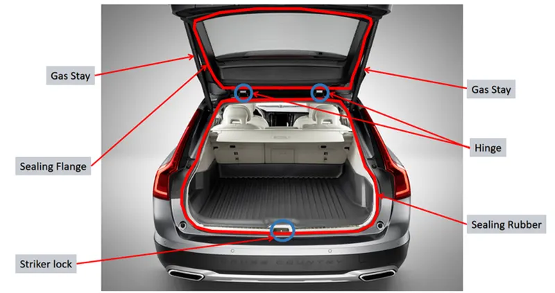
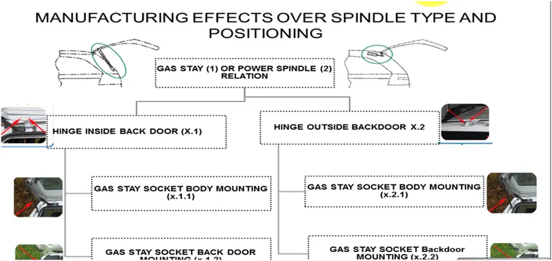
Gas stay types backdoor/liftgate/ta ilgate is an ideal and most commonly used tailgate mechanism from lowersegment car to luxury car segment. The ideal components of tailgate consist of a hinge,door,gas stay and some rubber beadings for sealing of door which is shown in the image below:
POWERED LIFT SYSTEM
Power trunk lid system is another sophisticated way of trunk/liftgate opening mechanism which is to automatically open and close of the trunk/liftgate and release of the latch by the touch of a button. The following image shows the component as used in the powered trunk/back door lift system.
Powered trunk lift system consists of a power latch,anti-pinch switch,PTG assembly's,PTG main switch.When the switch is pressed in the compartment or outside the power latch releases the latch and the entire backdoor is
opened.The anti-pinch switch is located in order to avoid acc idental hand insertion during the operation of the door.
3.0 MANUFACTURING PROCESS
Conventional tailgate assemblies are made from stamped metal panels welded together to form a tailgate. Latches are added on either side of the tailgate to engage a striker on the pickup sides. A handle operates the latches to open and close the tailgate assembly. Steel tailgate assemblies provide a durable and secure closure for the pickup bed.
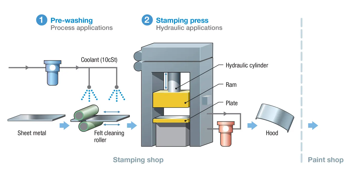
Another disadvantage of steel tailgate assemblies is the cost of the tooling required and equipment required to stamp metal tailgate components. Metal tailgate components are generally produced in a large stamping press. The stamping presses generally require finely machined tools made from hardened steel. The cost of tooling a metal tailgate is much more expensive.
3.1 MATERIAL FOR BODY PANELS
Materials for car body panels require certain specific characteristics to meet the industry’s challenges: rationalisation of specifications for leaner inventory, improved formability for reduced rejection rate and better quality. Higher Strength Low Alloy (HSLA) steels of thinner gauges, are getting preference for weight reduction and the resulting better fuel economy.Other quality characteristics under demand are higher yield stress (strength), toughness,fatigue strength, improved dent resistance as well as corrosion resistance in materials used for body panels for improved durability and reliability.
To obtain consistent quality of autobody skin panels without failures during stamping, the formability/ductility specifications of strip steels are the basic requirements.Most of the steels used in automotive application are aluminium-killed steels of about 0.7 to 0.9 mm thickness.
An intensive research and development are going on for alternate materials, manufacturing processes and stamping tools for sheet-metal components with the main objectives of cutting down the weight and unit cost of the vehicle. Simultaneously, the steel content of the car is falling with the use of aluminium and new materials, such as plastics. Aluminium may provide the most sought after solution to reduce the weight of the vehicles. A reduction of 30% in weight is achievable if the same strength, stiffness, and stability of the component are to be realised by substituting steel with aluminium. Possibility of significant reduction in die cost will be another advantage with aluminium. However, problems related to strength, serviceability,
manufacturability, and above all the cost, require effective solutions before the acceptance of aluminium as a substitute to steel for body panels. Plastics for bumpers,
3.2 STAMPING PROCESS
Stamping processes to be used for a panel depend on its design. However, normally the processes used extensively are blanking, drawing, piercing, forming, notching, trimming,hemming, etc. Blanking prepares the initial approximate form of the part in flat sheet. Drawing is generally the first operation to attain depth related form. Piercing, notching, hemming, are product design related operations. Trimming generally removes the extra material on the periphery of the panel provided for blankholding during draw operation. Decision on trim line is very important and becomes deciding factor to obtain good draw.
1. Blanking
When required, blanking is the first step of the stamping process. Blanking is the process of cutting larger sheet or coils of metal into smaller, more manageable pieces. Blanking is usually performed when a stamped metal piece will be drawn or formed.
2.Piercing
If a part requires slots, holes, or other cutouts, piercing can be employed. Piercing, which can be performed simultaneously with blanking, punches the requisite shapes out of the metal sheet.
3.Drawing
Drawing is the actual stamping in the metal stamping process. A punch forces a section of metal through a die, providing the primary shape of the part. When the depth of the part is less than the primary opening, it is considered shallow drawing; parts with a depth greater than the opening are deep drawn.
4.Bending
Bending is a fairly self-explanatory process. The part-in-progress is placed on a specially designed die and a ram pushes against the metal, providing the required bend. Bending is performed after drawing, as attempting to punch an already bent piece of metal causes the entire part to deform.
5.Hemming
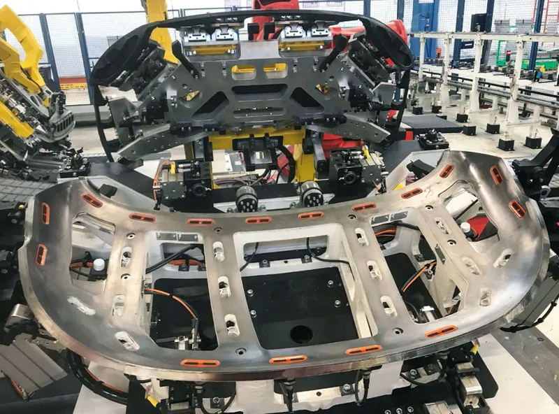
Hemming is a technology used by the automotive industry to join inner and outer closure panels together (hoods, doors, tailgates, etc.). It is the process of bending/folding the flange of the outer panel over the inner one. The accuracy of the operation affects significantly the appearance of the car’s outer surfaces and is therefore a critical factor in the final quality of a finished vehicle.
roller hemming :-The robotized hemming systems use a standard industrial robot integrated with a roller hemming head, offering a very flexible solution. This roller hemming head consists of a body, some guides and a number of rolls that are designed according to the geometry of the part in each case. 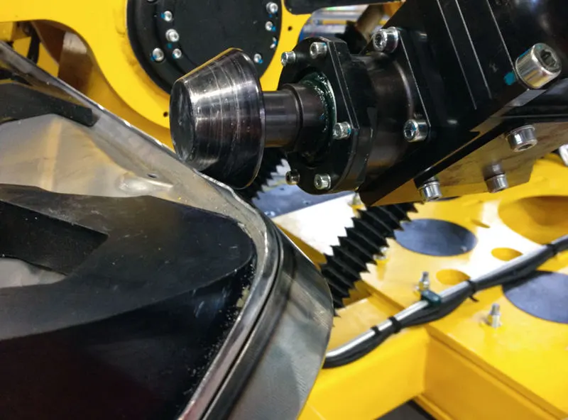
What Is Sheet Metal?
Sheet metal is one of the shapes and forms metal can be bought in. Sheet metal is any metal that has a thickness in between 0.5…6 millimetres.
There are other measurement units used to categorise metals by thickness, though.
Millimetres, Mils & Gauge
Foils, sheets and plates are pretty much the same, with the only difference being in thickness. Thickness is measured in 3 ways – millimetres, mils and gauges. While millimetre is a pretty straightforward unit, mils and gauges are only common in engineering and manufacturing.
One mil equals to a thousandth of an inch. As the British often use “mils” as a plural for millimetres, it can be a little confusing but the difference is important.
Gauge is another unit for measuring sheet metal thickness. Although official standards discourage the use of gauges, they are not all that rare. Gauge represents the thickness of a metal in relation to its weight per square foot. A higher gauge number means a smaller thickness.
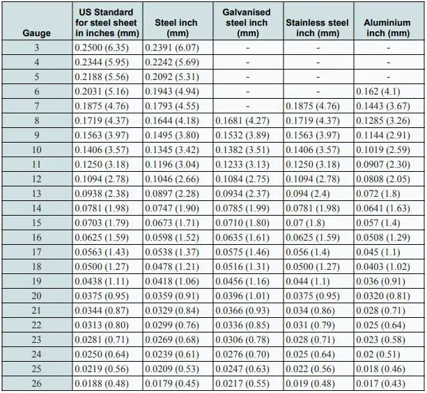
As it is related to the weight of a metal, the actual thickness (mm) for the same gauge, is different for various metals (e.g. 12 mm steel vs 12 mm aluminium).
Foil, Sheet and Plate
Having gone over the primary measurement systems, we can now look at the categorisation of foils, sheets and plates. For our purpose, we are going to stick with millimetres as the unit of measurement.
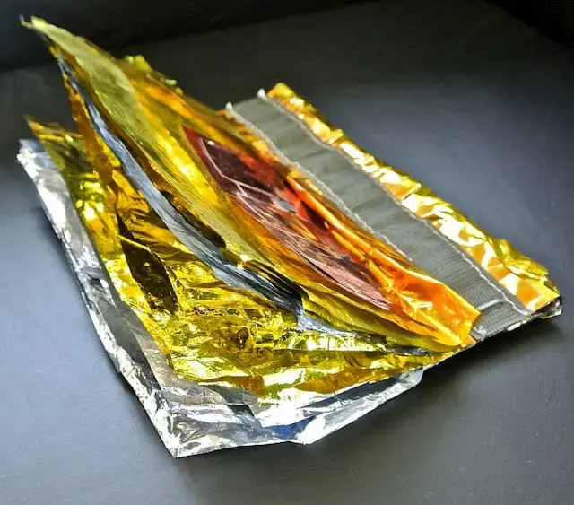
Metal foil is especially common with aluminium, often referred to as tinfoil. The thickness of foil is usually up to 0.2 mm.
Sheet metal is the next in line. The thickness of sheet metal starts from 0.5 mm and goes up to 6 mm. Anything above that is a metal plate.
The thin sheet metal is easy to form, while still providing great strength. At a relatively cheap price, it makes a great fit for most engineering purposes. That is why we see it everywhere around us.
At the end of the article, we will be discussing different forming methods used with sheet metal.
Common Materials :-
Pretty much all the common engineering metals are also used in the form of sheets. Some of them are carbon steel, stainless steel, copper and aluminium. Choosing the right one for you comes down to the application and requirements of your product.
Metal sheets have the same mechanical properties as the base metal. Thus, steel sheets have high tensile strength and durability suitable for use in constructions and machinery.
At the same time, copper sheets often find use as a decorative layer on modern buildings.
Standard Size :-
Standard measurements apply to both sheet sizes and thicknesses. While achieving large sheet sizes have a few workarounds through welding, you cannot really look past the thickness tables.
Standard Sheet Metal Measurements
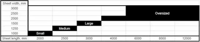
Knowing standard sheet sizes helps you with optimising your part layouts. Many times have we received parts for production that are just a bit larger than a standard size. That means more scrap and higher overall costs for the customer.
Also, another thing to bear in mind here is the availability of different sheet sizes. While small, medium and large sheets are pretty much always in stock at every sheet metal fabricator’s warehouse, oversized sheets may not be.
Many of them may also not have the machinery to cut such large sheets. So knowing your manufacturers’ capabilities comes in handy here.
Sometimes you can just weld together two smaller sheets but it is not the optimal solution. Especially when putting high emphasis on the aesthetics of your project.
Standard Sheet Metal Thickness
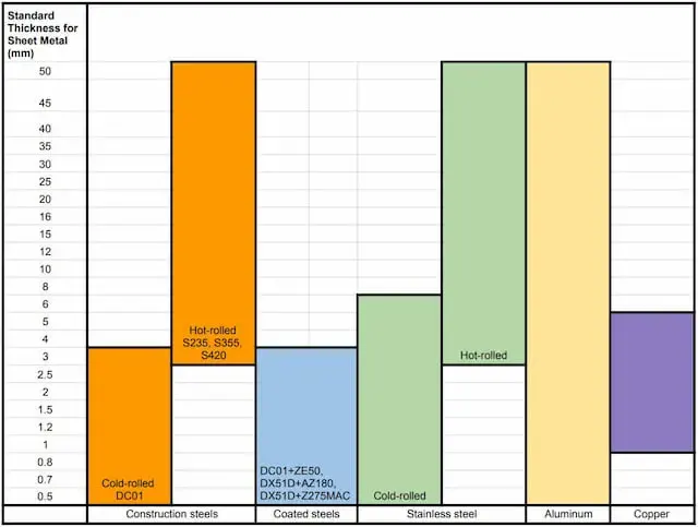
The table above shows standard thicknesses for both sheet metal and metal plates. As you can see, each type of metal has its own standards.
Also, it is good to not only pay attention to the starting and ending points but the actual values. Someone asking for non-standard thicknesses is quite frequent.
Exceptions to this table definitely exist. We would just advise you to follow these thicknesses because of the difficulty of finding the materials. All of the ones above are readily available with many sheet metal fabricators.
Get your manufacturing quote in seconds
- Quote in seconds
- Short lead times
- Delivery by Fractory
4.0 BACK DOOR DESIGN
The design consideration of back door are ,
- Visibility Criteria
- Force Dissipation
- Latch and Stricker Positions
- Hinge Position
- Gas Stay Position
- Hemming and Relief Areas
PARTS OF BACKDOOR
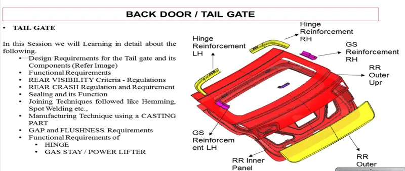
- Back door outer panel (upper and lower)
- Back door inner panel
- Hinge reinforcements
- Gas stay reinforcements
- Latch and striker reinforcements
- Wiper motor reinforcements
1. BACK DOOR OUTER PANEL
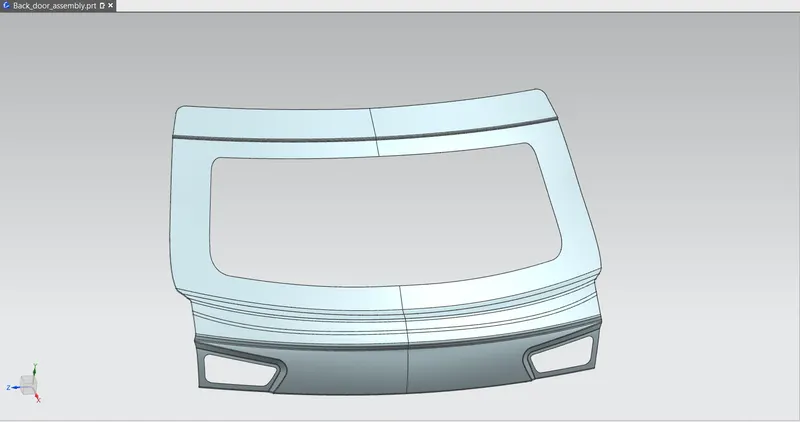
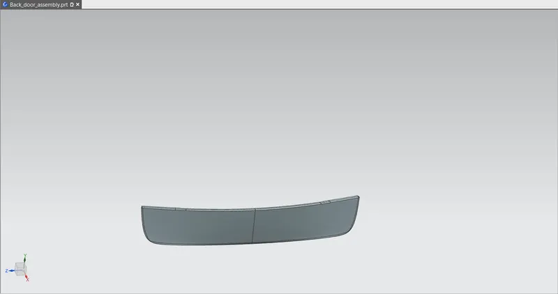
In this design back door is created as two different parts back door outer panel upper and lower. This outer panel designed based on visibility criteria and proper reliefs provided at the corner for hemming operation .The thickness of outer panel is 0.75 mm .
2.BACK DOOR INNER PANEL
Back door outer panel designed based on hinge, gas stay, wiper motor position and reinforcement as well as visibility criteria .Suitable tooling direction is created for trouble free manufacturing process.In this design stamping operations created based on this tooling direction. Embosses are provided in this design for force dissipation. In this design appropriate clearance given in mastic areas .The inner panel thickness is 0.75 mm
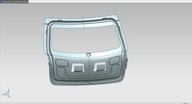
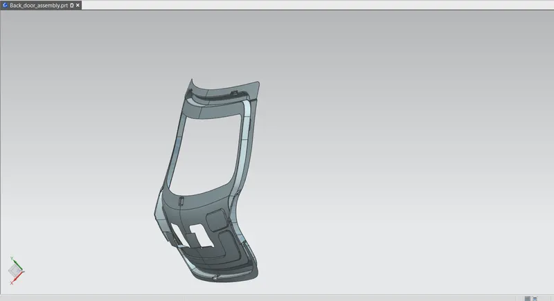
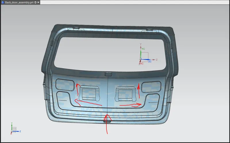
- Force dissipation
This inner panel design created by considering the force dissipation criteria.The embosses are created in such a manner that force will dissipate in to sides of the back door during a collision and prevent reaching inside the passenger cabin.Y and V embosses provided in the back door for force dissipation and improve the strength of the metal.
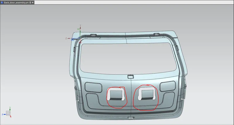
- Mastic Area
Mastics sealants used for joining of outer panel and inner panel. It increase the strength of back door and good NVH. So accurate clearance given for mastic sealant.
Reinforcements in inner panel
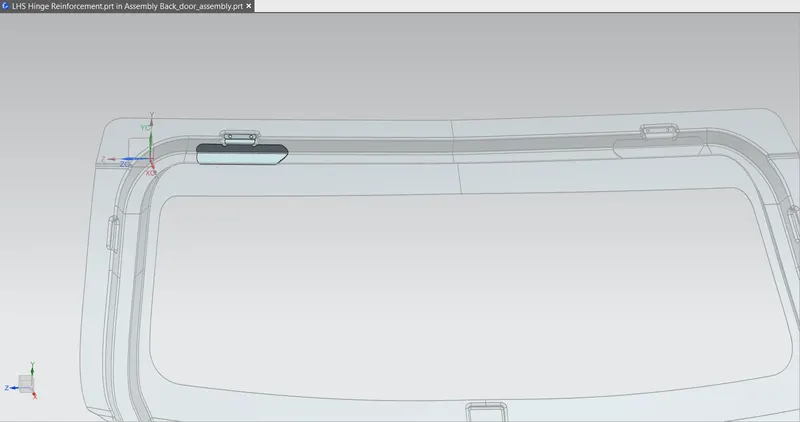
- Hinge reinforcement
In this design hinges provided on the top side of the door. Appropriate reinforcement given for hinge mounting areas to improve the strength.
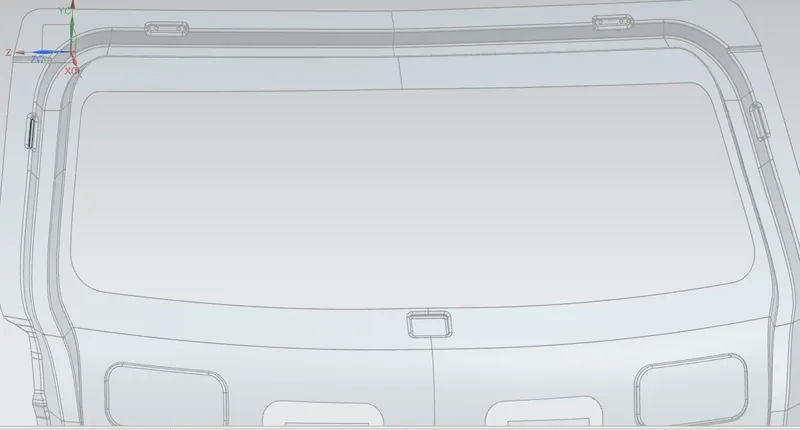
- Gas stay reinforcement
Gas stays support the weight of the back door while they are open. More load act on this region ,So suitable reinforcement provided for better strength
it is spot welded on the inner panel.
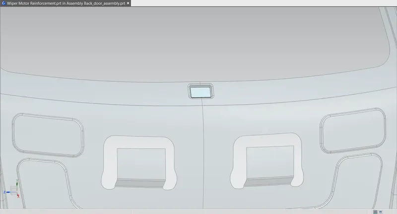
- Wiper motor reinforcement
Reinforcement provided in this region for fixing the wiper motor.
- Latch and striker reinforcement
The striker is designed to create a tight fit between the door and the seal on the cab. The door open and shut several times in a day.So more force acting on this area.The reinforcement given in the latch and striker mounting area to increase the strength.it is spot welded on the inner panel
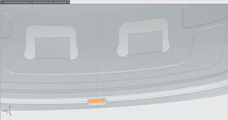
All reinforcement parts spot welded on the inner panel for better strength on that area.
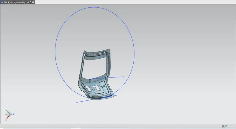
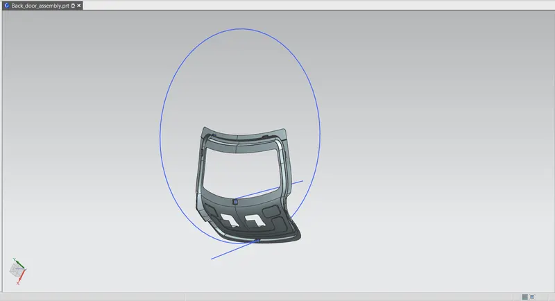
- trajectory
The trajectory is created to position the latch and striker .latch system must be able to catch the striker of the door the while closing. Circle is drawn from the hinge axis. The striker follow this path.
- Hemming
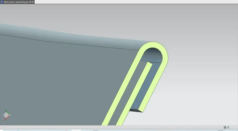
Hemming is a technology used by the automotive industry to join inner and outer closure panels together (hoods, doors, tailgates, etc.).In addition adhesive bond provide for excellent joining of panels it also reduce vibration .here this design 0.2mm clearance provided for hem glue .
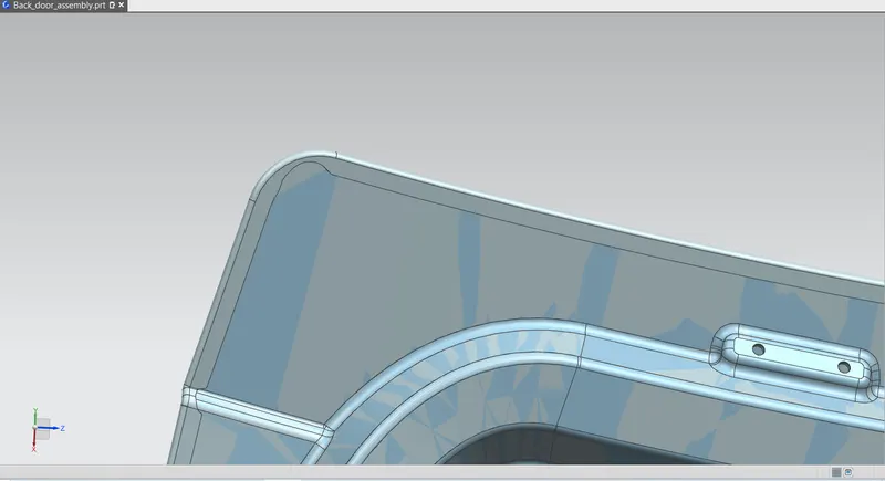
- Proper corner relief provided for trouble-free hemming operation
5.0 Draft Analysis
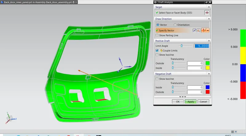
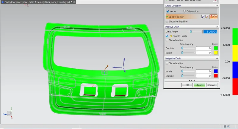
Draft analysis of inner panel is carried out through the tooling direction only.Only the green areas are accepteble and in worst case yellow region are accepteble but the blue and red region are never accepted.
The draft angle for alluminium casted panel is 2 to 3 degree is enough but if its steel then the angle is more than 7 degree.
In this project i considered it as steel and used 7 degree as draft angle and direction is choosen as tooling direction which is the deep drawn direction
6.0CONCLUSION
The backdoor is designed based on design considerations .Required reinforcement provided on inner panel. The design is checked by using draft analysis feature .