Design of backdoor
BACKDOOR DESIGN
Objective:
The Main objective is to design a Backdoor inner panel, outer panel upper & lower, positioning the hinge emboss, striker emboss, Gas Stay mounting holes, Wiper motor emboss, creating flanges to join inner panel & outer panel and its reinforcements with latch trajectory option using Siemens Nx application.
Introduction:
Here, we are going to study about how to create a Backdoor inner panel, outer panel, positioning the hinge emboss, striker emboss, Gas Stay mounting holes, Wiper motor emboss, creating flanges to join inner panel & outer panel and its reinforcements in siemens Nx Application. Using this application, how we are going to use tools step by step to complete the design. Then complete explanation about tools used to create backdoor and tests were conducted on the backdoor.
Design Methodology:
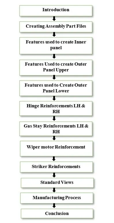
The design methodology of Backdoor design is explained through flow charts.
Introduction:
Backdoor:
A car backdoor is also known as Tailgate or Rear door or Hatchback or Trunk. Backdoor are one of the doors of the vehicle which are located next to the passenger seat which provides access to the luggage compartment. In the most of the cars, these backdoors are operated with the help of gas stay which in turn to reduces the effort required to lift the door. Some luxury cars have powered backdoor which in turn is driven by a power spindle automatically accessed by remote control. This kind of system is also called a powered trunk lid system hatchback or station wagons are sold as 3 doors or 5 doors models. In this case, the rear hatch is classified as door, this is because it enters the passenger compartment. The naming is mainly used in European countries. In case of safety, the backdoor design should meet the safety requirement of the rear collision.


Types of Mechanism used to lift backdoor:
- Gas Stay Type
- Power Spindle System
Gas Stay Type:
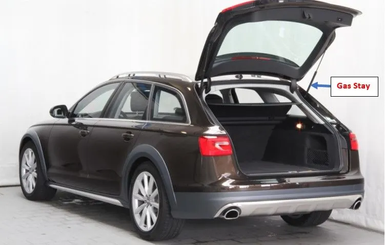
Gas Stay type backdoor is an ideal and most commonly used tailgate mechanism from lower segment cars to luxury segment cars. The ideal components of tailgate consist of hinges, door, gas stay, rubber beadings or rubber sealants to seal the doors without any gap between door & body in white structure.
Power Spindle System:
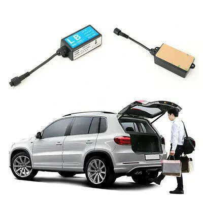
Power spindle system is another sophisticated way of trunk or tailgate opening mechanism which is automatically open and close the hatchback and release of the latch by the touch of a bottom. Power spindle system consists of a power latch, anti-pinch switch, PTG assembly, PTG main switch. When the switch is pressed in the compartment or outside the power latch releases the latch and the entire backdoor is opened. The pinch switch is located in order to avoid accidental hand insertion during the operation of the door.
Data’s to be Used:
- Outer Panel Thickness: 0.75 mm
- Inner Panel Thickness: 0.75 mm
- Reinforcements Thickness: 1.5 – 2 mm
Creating Assembly Part Files:
- Start Siemens Nx application to create assembly sheet. Then click ok to start design.
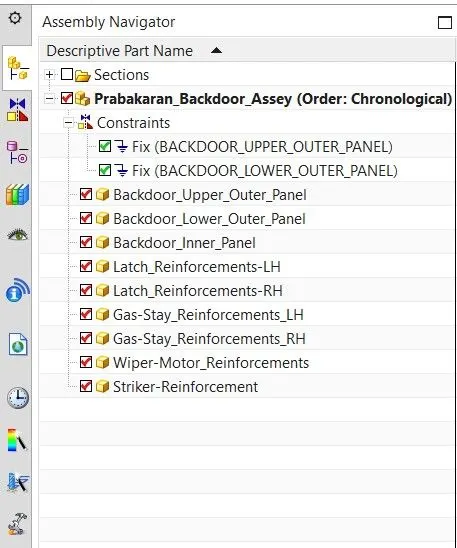
- Clicking on the assembly tab, click on create new icon, the new component file dialog box appears, in that select model part file and name it as Backdoor outer panel upper and choose the folder location to save. Then click ok to procced.
- Sample image were attached below for reference.
Features Used to Create Inner Panel:
- Clicking on the Assembly navigator tab, double click on the created part file to start designing.
- Before starting design, we need to down the surface design provided to us to create backdoor.
- Start editing the downloaded surface file, to resolve disjoints on the outer surface file to create new modified surface files.
- The new modified files were extracted into two files named as Outer panel Upper and Outer Panel Lower.
- The newly modified Outer panel upper & Outer panel Lower is copied to the Assembly sheet and providing fixed constraints to the files as shown in above image.
- Now Linking Outer Panel Upper & Outer Panel Lower to Inner panel assembly through wave geometry linker.
- Clicking on the part navigator tab, the two linked body appears. Right click on the linked bodies to add to feature group name as Parent geometry to secure the design.
- Again, extracting the linked body files from the parent geometry and assigning feature group name as Working geometry.
- Clicking on the Sketch tab, to create tooling direction lines on the XY plane to produce the part with the help of tooling direction.
- Assigning feature group name to the sketch as Tooling Direction.
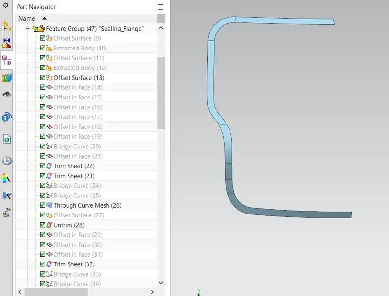
- To create a Sealing flange in Inner panel Design, the following commands were used.
- The commands are Offset Surface, Offset curve in face, Bridge curve, Trim sheet, Through curve mesh, Untrim, Sketch, Projected curve, Sew and Extracted Body.
- The above commands were used to create Sealing flange and values may differ according to our design.
- The sealing flange should maintain minimum value of 15 mm to maximum of 30 mm to but with rubber beading to avoid water & Dust enters inside the car.
- Assigning feature group name as sealing flange to the created design from Offset surface (9) to Sew command (45).
- Reference image was attached below.
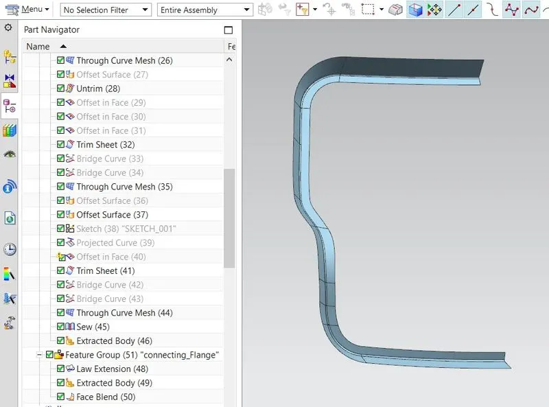
- Connecting Flange is created from the sealing flange.
- The commands were used to create connecting flange are Law Extension, Face Blend and Extracted body.
- Assigning feature group name as connecting flange from law extension (48) to Face Blend (50).
- The reference image has been attached below.
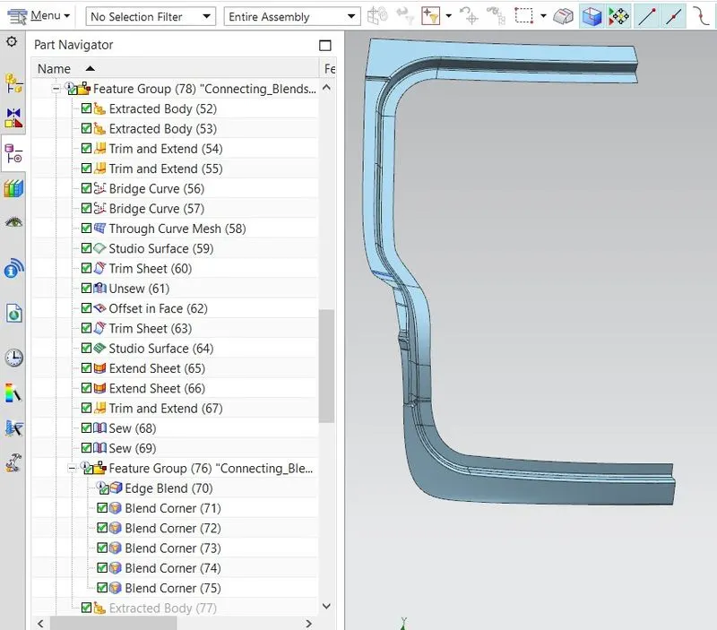
- Connecting blends is created from the connecting flange design.
- The commands were used to create connecting blends are Trim & Extend, Extracted Body, Bridge curve, Through Curve Mesh, Studio Surface, Trim sheet, Unsew, Offset curve in face, Extend Sheet, Sew, Edge Blend and Blend Corners.
- The values may differ according to our design.
- Assigning feature group name as connecting blends from Extracted body (52) to Blend Corner (75).
- And creating an associative copy from connecting blends through Extracted Body.
- The reference image has been attached below.
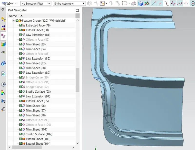
- Creating Windshield design from the connecting blend extracted body.
- The commands were used to create Windshield are Extracted face, Extend Sheets, Law Extensions, Offset curve in faces, Trim Sheets, Bridge Curves, Studio Surface, Sew, Edge Blend, Blend Corners and Extracted body.
- The values may differ according to our design and commands may be used again and again to achieve our design.
- Assigning Feature group name as Windshield from Extracted face (79) to Extracted body (119).
- The reference image has been attached below.
- Creating Inner Panel Design from Windshield extracted body.
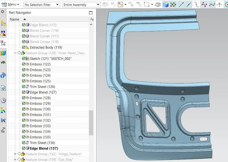
- The commands were used to create Inner panel designs are Sketch, Embosses, Trim sheets, Edge Blends.
- The values may differ according to our design and commands may be used again and again to achieve our design.
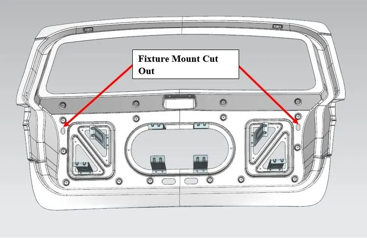
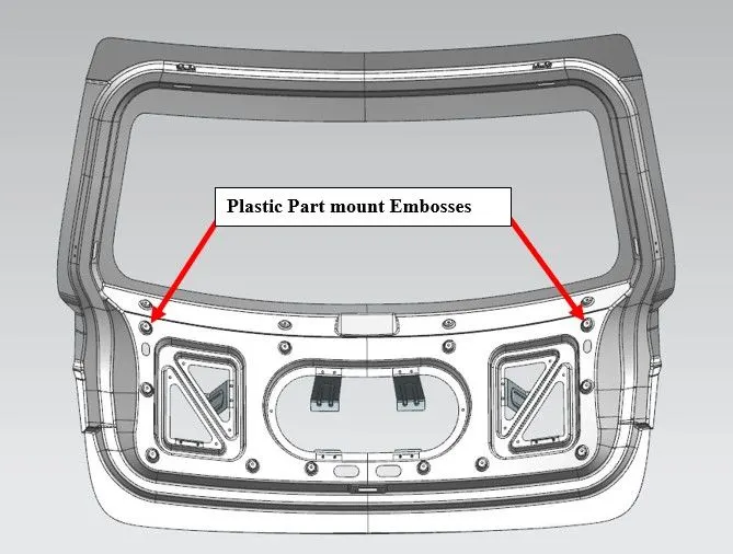
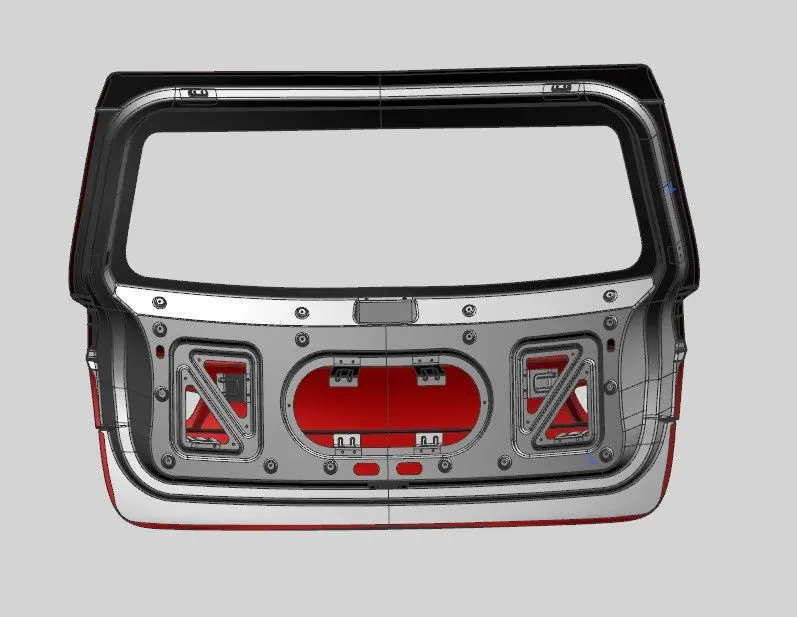
- While designing Inner sheet, we need to consider for Plastic part mount, cut outs for access to tail lamps, Wiper motor assembly, Striker assembly, Gas stays, Hinges and cut outs for fixture mount.
- Assigning Feature group name as Inner panel Designs from Sketch (121) to Edge blend (137).
- The reference image has been attached below.
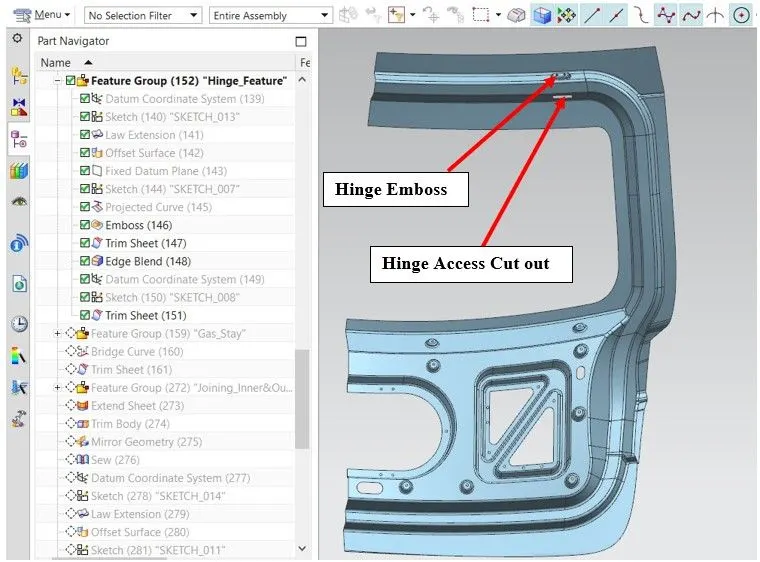
- Creating Hinge emboss in the Inner sheet.
- The commands were used to create hinge emboss are New Datum coordinate system, sketch, Law Extension, Offset Surface, Curves & Points datum Plane, Sketch, Projected Curve, Emboss, Trim Sheet, Edge Blend.
- The values may differ according to our design and commands may be used again and again to achieve our design.
- The cut outs were created to access the hinge assembly to tighten the nuts.
- Assigning Feature group name as Hinge Feature from Datum coordinate system (139) to Trim sheet (151).
- The reference image has been attached below.
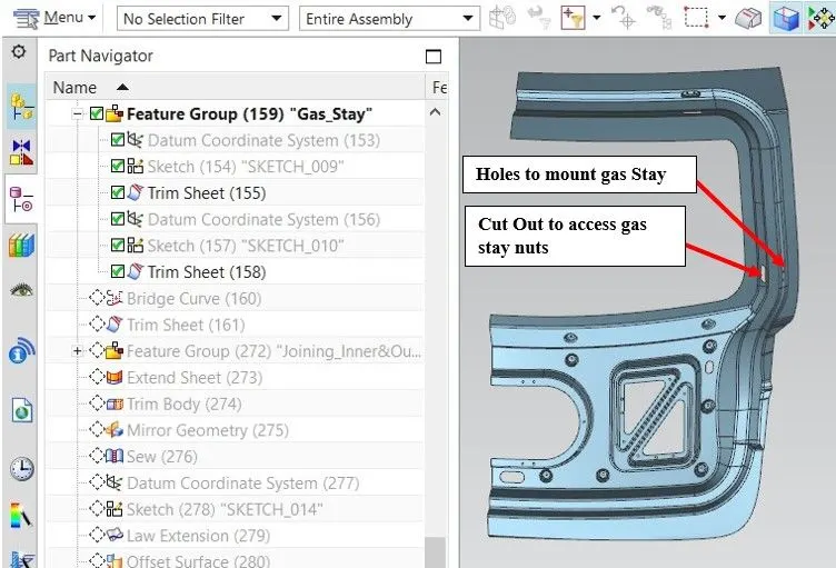
- Creating Gas Stay holes in the inner sheet.
- The commands were used to create gas stay holes and Cut outs are New Datum coordinate system, Sketch, Trim sheet.
- The values may differ according to our design and commands may be used again and again to achieve our design.
- The cut outs were created to access the hinge assembly to tighten the nuts.
- Assigning Feature group name as Gas Stay from Datum coordinate system (153) to Trim sheet (158).
- The reference image has been attached below.
- Trimming the corners to avoid sharp corners.
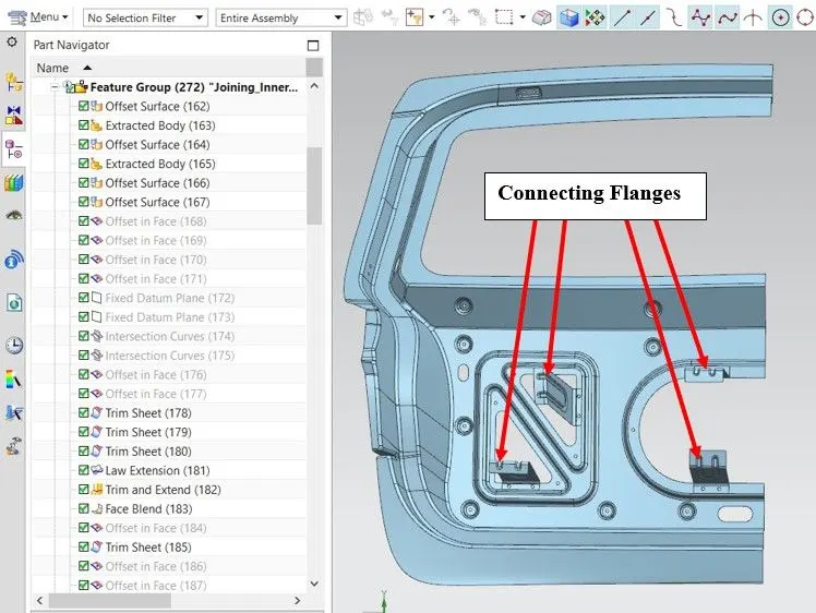
- Creating Connecting Flanges to join the Inner panel and Outer panel Upper & Lower.
- The Commands were used to create connecting flanges are Offset Surface, extracted body, offset curve in face, on curve plane, Intersection Curves, Trim sheet, Law Extension, Trim & Extend, Face blend, Extend Sheet, Bridge Curves, Sketch, Projected Curves, Bead Feature, Emboss Body and Edge Blends.
- The above commands were repeated to create a required design and also changing the values.
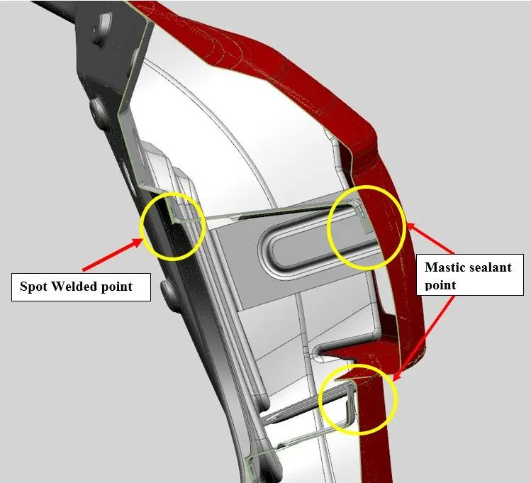
- One end of the flange was connected to the inner sheet which is spot welded and the other end is connected to the outer panel upper & lower with the help of mastic sealants to avoid noise, vibrations on the hatchback and to improve NVH.
- Beads were created to strengthen the flanges.
- Assigning Feature group name as Connecting Flanges from Offset surface (162) to Edge Blend (271).
- The reference image has been attached below.
- After completing the design Examining the part to check disjoints & patches occurred in the design or not. If occurs, we can rectify to apply Mirror Geometry using extending the sheet for 5 mm at the centre. And using Trim body command, the extended sheet can be trimmed off with respect to XY plane.
- Now mirroring the part using mirror geometry command with respect to XY plane.
- The reference image has been attached below.
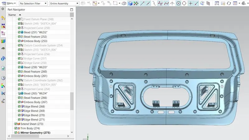
- Again, re-examining the mirror geometry to check any disjoints formed. If no disjoints formed click close.
- Finally sew the parts to combined as one part.
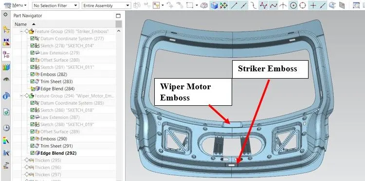
- Creating Striker Emboss & Wiper Motor Emboss in the sewed inner sheet.
- The commands were used to create Striker emboss and Wiper motor emboss are New Datum coordinate systems, sketches, Law Extensions, Offset Surfaces, Embosses, Trim sheets, Edge blends.
- The values may differ according to our design and commands may be used again and again to achieve our design.
- Assigning Feature group named as Striker Emboss from Datum coordinate system (277) to Edge Blend (284).
- And Assigning Feature group named as Wiper Motor Emboss from Datum coordinate system (285) to Edge Blend (292).
- The Reference image has been attached below.
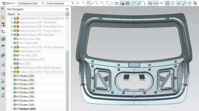
- Finally, thicken command is used to Thicken the part with respect to 0.75 mm.
- The image has been attached below for the reference.
Features Used to Create Outer Panel Upper:
- Clicking on the Assembly navigator tab, double click on the created Outer Panel Upper part file to start design.
- Unhide the Inner panel to Link with Outer panel upper part. Using Wave geometry linker, the inner panel is linked into the Outer panel Upper to start design.
- Clicking on the part navigator and selecting the linked body to assign feature group name as Parent Geometry to secure the design.
- Extracting the body from linked body from parent geometry and assigning feature group name as Working Geometry.
- Creating hemming flange to the outer panel upper to be spot welded with inner panel.
- The Commands were used to create hemming flanges are Bridge curves, Trim sheets, Offset surface, Offset curve in faces, through curve mesh, Sew, Swept, on curve plane, Intersection curves, Sketch and Curve on face.
- The above commands were repeated to create a required design and also changing the values.
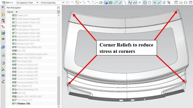
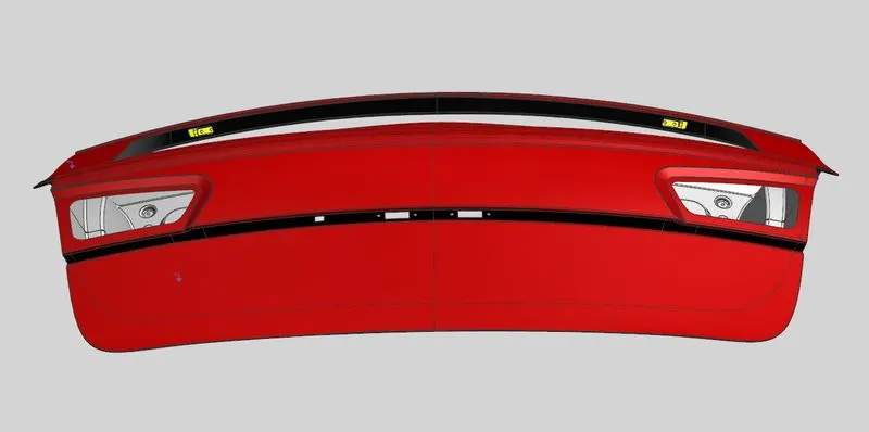
- In this Corner relief curves were created to avoid stress on the curved areas while hemming.
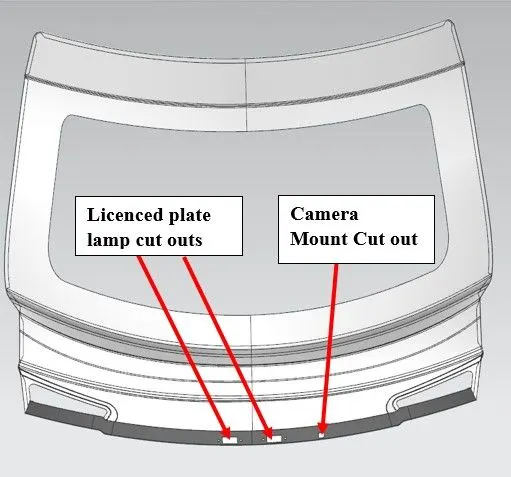
- Cut outs were created on the outer panel upper for Licenced plate lamps and to mount cameras.
- Mirror Geometry command is used to mirror the part.
- Applying Sew command to combine the parts as one-part file.
- Examining the part to check disjoints and patches. If everything is ok, then click close to apply thicken.
- Applying thicken to the created part with respect to 0.75 mm Thickness.
- The image has been attached below for the reference.
Features Used to Create Outer Panel Lower:
- Clicking on the Assembly navigator tab, double click on the created Outer Panel Lower part file to start design.
- Unhide the Inner panel to Link with Outer panel lower part. Using Wave geometry linker, the inner panel is linked into the Outer panel Lower to start design.
- Clicking on the part navigator and selecting the linked body to assign feature group name as Parent Geometry to secure the design.
- Extracting the body from linked body from parent geometry and assigning feature group name as Working Geometry.
- Creating hemming flange to the outer panel lower to be spot welded with inner panel.
- The commands were used to create hemming flange are Offset Surface, Offset curve in face, Trim Sheet, Bridge Curves, Swept, on curve datum planes, through curve mesh, Sew, Extend sheet, Trim body and Curve on Surface.
- The above commands were repeated to create a required design and also changing the values.
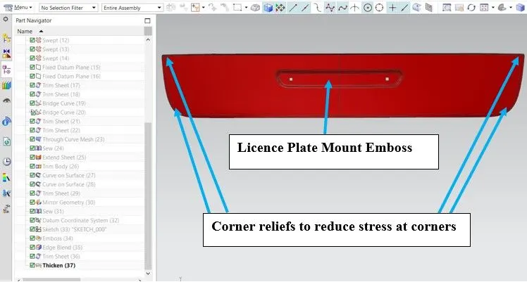
- In this Corner relief curves were created to avoid stress on the curved areas while hemming.
- Mirror Geometry command is used to mirror the part.
- Applying Sew command to combine the parts as one-part file.
- Examining the part to check disjoints and patches. If everything is ok, then click close to apply thicken.
- Creating emboss and cut outs for licence plate mounting.
- The commands were used to create licenced emboss are New Datum coordinate system, sketch, Emboss, Trim sheet and Edge Blend.
- Applying thicken to the created part with respect to 0.75 mm Thickness.
- The image has been attached below for the reference.
Hinge Reinforcement LH:
- Clicking on the Assembly navigator tab, double click on the created Hinge Reinforcement LH part file to start design.
- Unhide the Inner panel to Link with Hinge Reinforcement LH part. Using Wave geometry linker, the inner panel is linked into the Hinge Reinforcement LH to start design.
- Clicking on the part navigator and selecting the linked body to assign feature group name as Parent Geometry to secure the design.
- Extracting the body from linked body from parent geometry and assigning feature group name as Working Geometry.
- The commands were used to create reinforcement are Offset surface, curve on datum planes, offset curve in face, Trim Sheet, extend sheet.
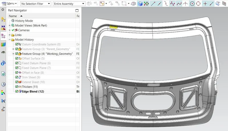
- Applying thicken command to thicken the reinforcement with respect to 1.5 mm. And applying edge blend command to avoid sharp corners at the edges.
- The image has been attached below for the reference.
Hinge Reinforcement RH:
- Clicking on the Assembly navigator tab, double click on the created Hinge Reinforcement RH part file to start design.
- Unhide the Inner panel to Link with Hinge Reinforcement RH part. Using Wave geometry linker, the inner panel is linked into the Hinge Reinforcement RH to start design.
- Clicking on the part navigator and selecting the linked body to assign feature group name as Parent Geometry to secure the design.
- Extracting the body from linked body from parent geometry and assigning feature group name as Working Geometry.
- The commands were used to create reinforcement are Offset surface, curve on datum planes, offset curve in face, Trim Sheet, extend sheet.
- Applying thicken command to thicken the reinforcement with respect to 1.5 mm. And applying edge blend command to avoid sharp corners at the edges.
- The image has been attached below for the reference.
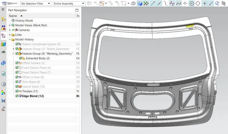
Gas Stay Reinforcement LH:
- Clicking on the Assembly navigator tab, double click on the created Gas Stay Reinforcement LH part file to start design.
- Unhide the Inner panel to Link with Gas Stay Reinforcement LH part. Using Wave geometry linker, the inner panel is linked into the Gas Stay Reinforcement LH to start design.
- Clicking on the part navigator and selecting the linked body to assign feature group name as Parent Geometry to secure the design.
- Extracting the body from linked body from parent geometry and assigning feature group name as Working Geometry.
- The commands are used to create Gas stay reinforcements are Offset surface, on curve datum planes, offset curve in face, Trim sheet.
- Applying thicken command to thicken the reinforcement with respect to 1.5 mm. And applying edge blend command to avoid sharp corners at the edges.
- The image has been attached below for the reference.
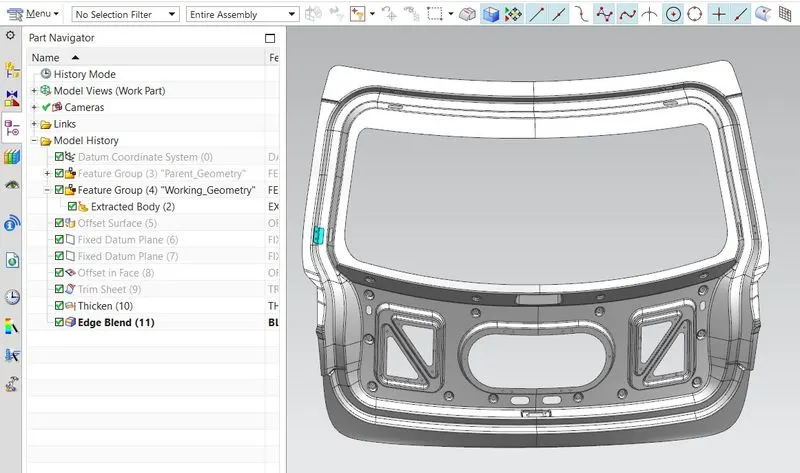
Gas Stay Reinforcement RH:
- Clicking on the Assembly navigator tab, double click on the created Gas Stay Reinforcement RH part file to start design.
- Unhide the Inner panel to Link with Gas Stay Reinforcement RH part. Using Wave geometry linker, the inner panel is linked into the Gas Stay Reinforcement RH to start design.
- Clicking on the part navigator and selecting the linked body to assign feature group name as Parent Geometry to secure the design.
- Extracting the body from linked body from parent geometry and assigning feature group name as Working Geometry.
- The commands are used to create Gas stay reinforcements are Offset surface, on curve datum planes, offset curve in face, Trim sheet.
- Applying thicken command to thicken the reinforcement with respect to 1.5 mm. And applying edge blend command to avoid sharp corners at the edges.
- The image has been attached below for the reference.
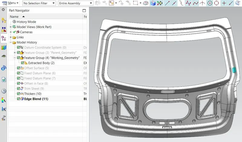
Wiper Motor Reinforcement:
- Clicking on the Assembly navigator tab, double click on the created Wiper Motor Reinforcement part file to start design.
- Unhide the Inner panel to Link with Wiper Motor Reinforcement part. Using Wave geometry linker, the inner panel is linked into the Wiper Motor Reinforcement to start design.
- Clicking on the part navigator and selecting the linked body to assign feature group name as Parent Geometry to secure the design.
- Extracting the body from linked body from parent geometry and assigning feature group name as Working Geometry.
- The command is used to create wiper motor reinforcement are Offset surface.
- Applying thicken command to thicken the reinforcement with respect to 2 mm.
- The image has been attached below for the reference.
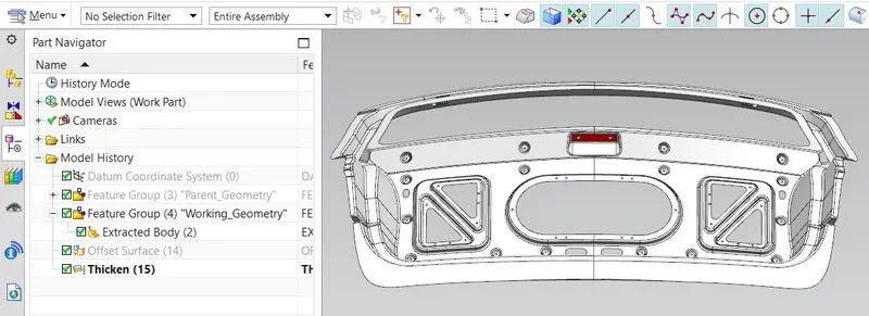
Striker Reinforcement:
- Clicking on the Assembly navigator tab, double click on the created Striker Reinforcement part file to start design.
- Unhide the Inner panel to Link with Striker Reinforcement part. Using Wave geometry linker, the inner panel is linked into the Striker Reinforcement to start design.
- Clicking on the part navigator and selecting the linked body to assign feature group name as Parent Geometry to secure the design.
- Extracting the body from linked body from parent geometry and assigning feature group name as Working Geometry.
- The command is used to create wiper motor reinforcement are Offset surface.
- Applying thicken command to thicken the reinforcement with respect to 1.5 mm.
- The image has been attached below for the reference.
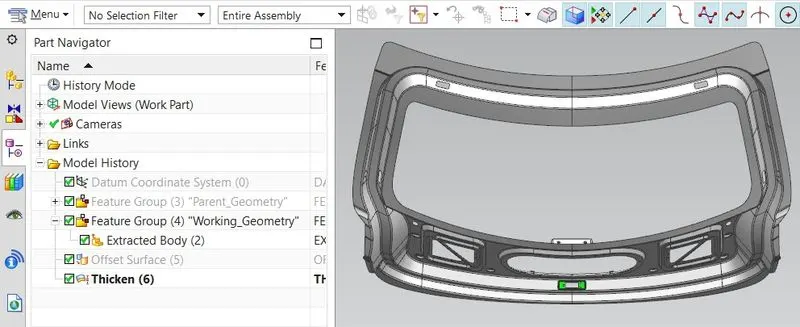
Standard Views:
Front View:
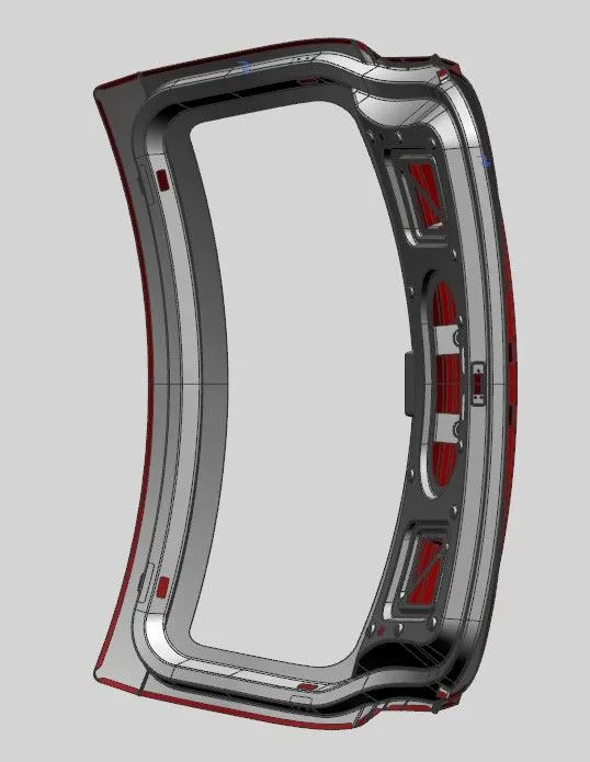
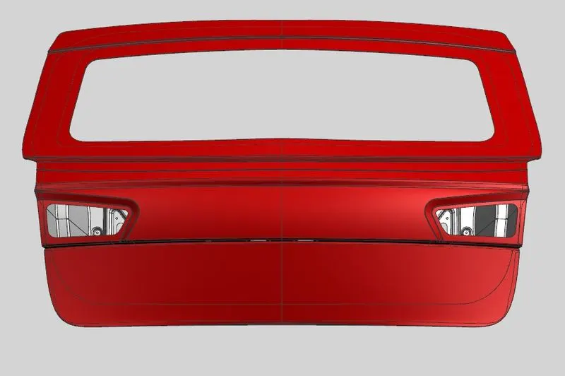
Back View:
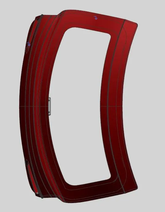
Top View:
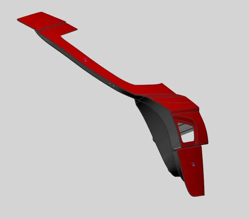
Isometric View:
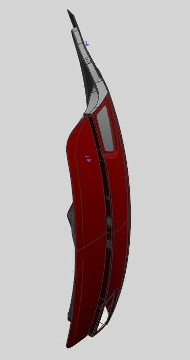
YZ Plane View:
Manufacturing Process:
Recently, there have been two approaches to reducing automobile weight. One is by using material lighter than Steel and the other is by redesigning the steel structure. Although the former seems very effective, it is very expensive so that it may only be used for an expensive automobile industry is trying to use steel, which is not costly and recyclable. Light weight steel can be achieved by improving the performance of the Structure or adopting by improving the performance of the structure or adopting new manufacturing techniques. One of the efforts is the ULSAB (Ultra-Light Steel Auto Body) concept.
ULSAB suggests three main weight reduction techniques such as hydro forming and Tailor Welded Blank (TWB).
Tailor Welded Blank:
A Tailor Welded Blank is a blank that is compared of two separate pieces of sheet metal that have been welded together prior to stamping. TWB allows the welding of the different grades, different thickness or different corrosion coating together in order to give the properties needed in different areas, without increasing the number of tools needed to form the part and eliminating the fit ability concerns. They also allow a high degree of flexibility in designing parts and large blanks can be formed from much smaller sheets. The use of TWB would reduce the weight of the car. Having the ability to selectively requirement on a door inner is in the region where the hinges attach to the panel.
Load Cases – General Analysis:
The following load cases were under gone after manufacturing the Backdoor. They are
- Bend Test
- Torsion Test
- Abuse Case
- Dent Test
- Assembly Load case
- Endurance
Bend Test:
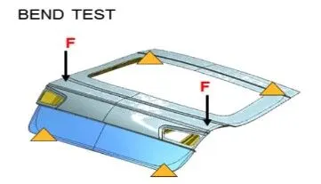
The bend test is a simple and inexpensive qualitative test that can be used to evaluate both the ductility and soundness of a material. It is often used as a quality control test for butt-welded joints, having the advantage of simplicity of both test piece and equipment.
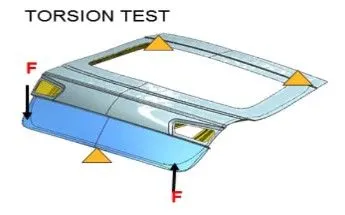
Torsion Test:
The torsion and beaming test are designed to check modified vehicles for the two main strength requirements of any chassis: torsional rigidity and beam strength.
Torsional rigidity is a vehicle’s backdoor ability to resist twisting under applying load to the backdoor. Beam strength is the strength of the backdoor along its length. To conduct torsional test, hinges and striker position were constrained and the gradual load is applied at the down end of corners.
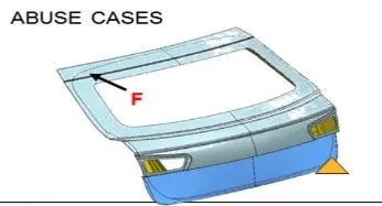
Abuse Cases:
Abuse cases are Over slamming and hanging when the door is in open condition.
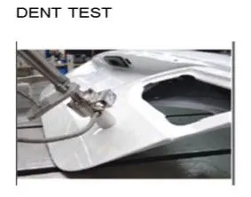
Dent Test:
Dent test is a test, when the load applied to backdoor and after some point checking the door retracts to its original position or not.
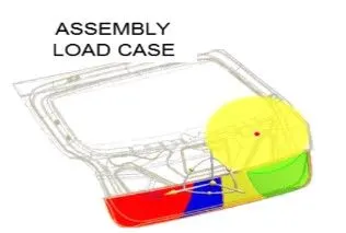
Assembly Load Case:
Assembly load case is a case, while assembling the vehicle the force is applied to the backdoor and checking whether the load is withstanding or not.
Endurance Test:
Endurance test is a workability test. This test is conducted by open and closing of backdoor to ‘n’ number of cycles, where at last we check the door behaviour at the end of the cycles.

Draft Analysis:
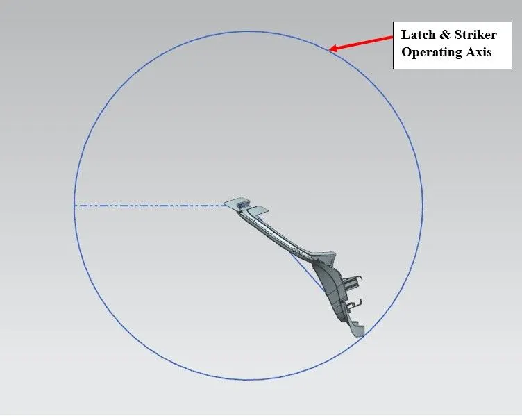
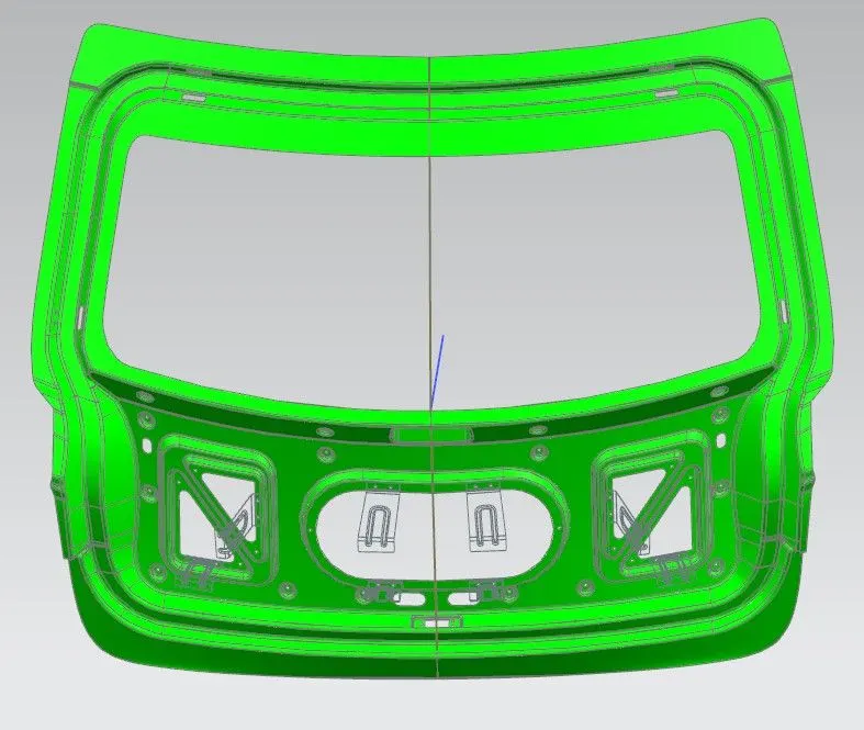
Draft Analysis is done to check whether the part is manufacturable or not. It is not a sure shot confirmation that the part is manufacturable, but it is used to check the draft angle on the part. The minimum draft angle is to maintain 7 mm. The tooling direction for the analysis is perpendicular to the wiper motor area.
Deep drawing:
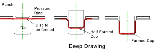
It is a sheet metal forming process in which a sheet metal blank is radially drawn into a forming die by the mechanical action of a punch. It is thus a shape transformation process with material retention. The process is considered "deep" drawing when the depth of the drawn part exceeds its diameter.
- We give a positive draft or an angle for a better drawing process.
- Deep drawing processes are divided into three types:
- Deep drawing with tools
- Deep drawing with active means
- Deep drawing with active energy
Hemming Process:
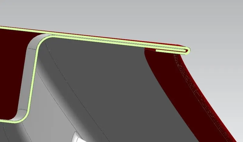
Hemming is a forming operation in which the edges of the sheet are folded over another part in order to achieve a tight fit. Normally hemming operations are used to connect parts together, to improve the appearance of a part, and to reinforce part edges. Conventional die hemming. Hemming is the process in which the edge is rolled flush to itself, while a seam joins the edges of two materials. In Backdoor Design, hemming is used in assembly as a secondary operation after deep drawing, trimming ang flanging operations to join two sheet metal parts (Outer and Inner panel) together. In between the outer and inner panel, there will be gluing after or before the hemming process because to reduce NVH and also sticking the two panels.
Roll Hemming:
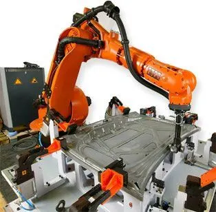
The hemming roller is guided by an industrial robot to form the flange. For manufacturing the backdoor, we choose Roll Hemming process for smooth finishing.
Conclusion:
Finally completed the backdoor design in Siemens Nx application as per the design requirements.