Design of backdoor
DESIGN OF BACK DOOR:
AIM:
To design the back door using given class A surface with follow the design consideration.
INTRODUCTION OF BACK DOOR:

The back door is a hinged door/tailgate at the rear of the vehicle. It may be used for loading and unloading cargo, or to get passengers in and out, in case there are seats present at the rear. The back door comprises of certain components which form the back door assembly together.
COMPONENT OF BACK DOOR:
- OUTER PANEL
- INNER PANEL
- LATCH STICKER REINFORCEMENT
- HINGE REINFORCEMENT
- GASSTAY REINFORCEMENT
- WIPER MOTAR MOUNTING REINFORCEMENT
OUTER PANEL:
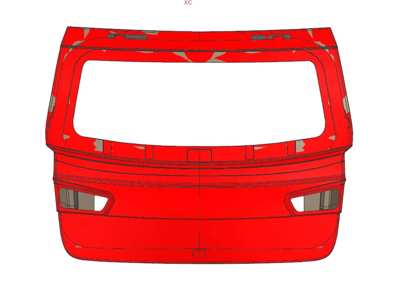
Outer panel is upper surface of the back door it also the aesthetic surface of the back door. This surface is input of design the backdoor. And also inner panel and outer panel connect together at the process of hemming.
INNER PANEL:
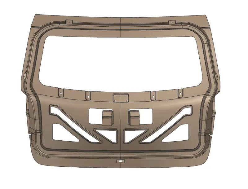
It is where most of the reinforcements and components are mounted. It is manufactured either by casting (aluminum) or sheet metal stamping (steel). Thickness of inner panel is 0.75 mm.
REINFORCEMENT:
Reinforcements are provided to provide support and add extra material to the sheet metal part to increase its strength near component installation regions and minimize the impact of collisions. We have considered following reinforcements during our design. The reinforcements maybe manufactured by stamping. Thickness of all reinforcements is 0.75mm.
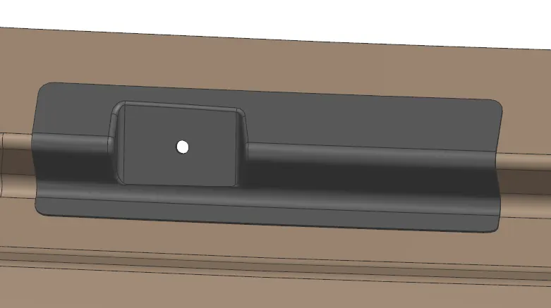
HINGE REINFORCEMENT
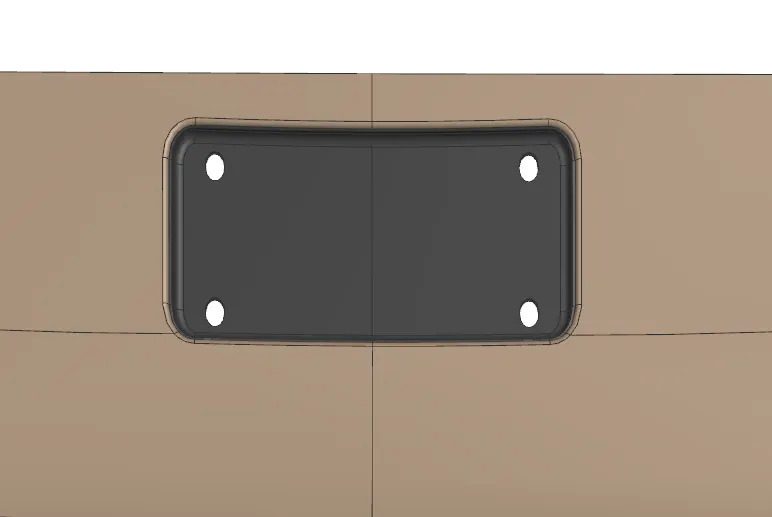
WIPER MOTAR REINFORCEMENT
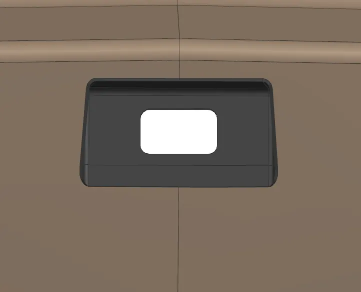
LATCH AND STICKER REINFORCEMENT
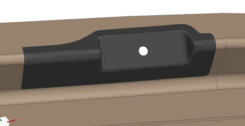
GAS STAY REINFORCEMENT
DESIGN CONSIDERATION OF BACK DOOR:
-
Functional Requirement of Hinge and gas stay
-
Rear visibility criteria
-
Luggage volume
-
Crash Analysis
- Gap and flushness Requirements
DESIGN PROCEDURE:
- We start with the styling surface that is provided to us, and consider top-down approach for this assembly modeling.
- First, we create the assembly and then create the components in the assembly file itself.
- Inner and outer panel are the largest parts and all other parts depend on them so we start with them.
- Also, the given styling surface is part of the outer panel so we create it first. Using various commands and features we design the outer panel from the styling surface.
- We have 2 parts for outer panel, which are separated by a flange, hence we create outer panel upper and lower respectively.
- They will be spot welded with each other. It is necessary to make sure that all the surfaces are properly joint to their adjacent surface and there are no disjoints at their intersection edges to avoid further errors.
- Also, Inner and outer panels are connected by hemming process so we can come back to outer panel and do that that after completion of inner panel.
- Now, as we know inner panel is at a particular distance from outer panel, we offset the outer panel surface and design inner panel on the same.
- Inner panel is important as most the mountings will be done on it. Before starting inner panel design, we need to define the tooling direction as a reference for manufacturing team. Then we design the inner panel.
- While designing the inner panel we need to consider various factors like the mounting point positions, mastic sealant application positions and the cut outs in sheet to make access to tail light assembly easier.
- As the bottom center part of inner panel is not connected to outer panel, we need to create a surface that comes out and connects to outer panel as shown in the image.
- This part will be connected to outer panel using mastic sealant. Also, the hinge embosses must be taken by considering proper directions.
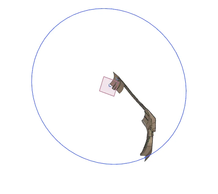
- The emboss surface must be parallel to z-axis to get proper geometry for the latch striker path curve. Then we draw a line connecting the hinges, such that it forms the hinge axis (axis around which the door rotates while opening or closing).
- Then we can draw a circle with center at the hinge axis and circumference passing somewhere around the emboss endcap. So that when we get the emboss for latch striker mounting, we can take the end cap by creating a plane normal to the path (using On Curve) in the direction normal to the path of striker.
- Thus, after some trial and error, we can adjust the emboss and the circle dimensions properly.
- As the inner and outer panel are connected by hemming process, we can complete the hemming after completion of inner panel.
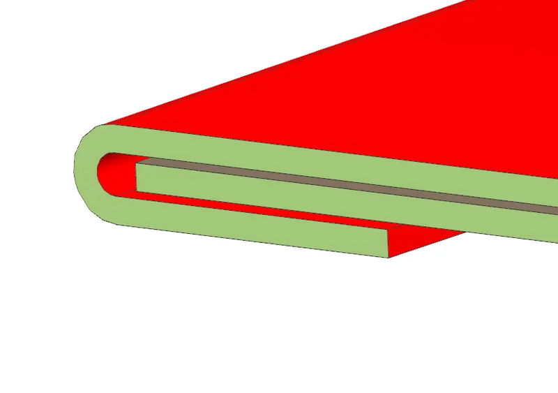
HEMMING:
- Hemming is the metelworking process in which a sheet metal edge is rolled into itself.
- The outter surface of the panel is rolled 2 or 3 times over the inner panel.
- In first roll the panel is bent slinghtly,and in the second roll the shhet matel is rolled even more and in the last roll it completely fits or covered the inner panel.
- There must be a 0.2mm gap between outter and inner pannel in both upper and lower side.
SPOT WELDING:
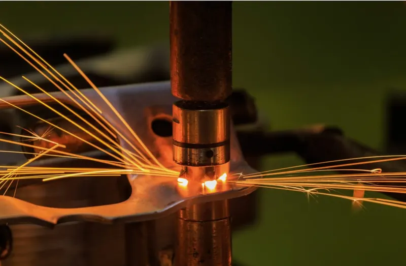
Spot Welding is a form of resistance welding also known as Resistance Spot Welding (RSW). Spot Welding involves using heat produced by resistance to an electrical current to join materials together. The current heats the materials to a point where they become malleable. The use of strong pressure bonds them together.
DRAFT ANALYSIS:
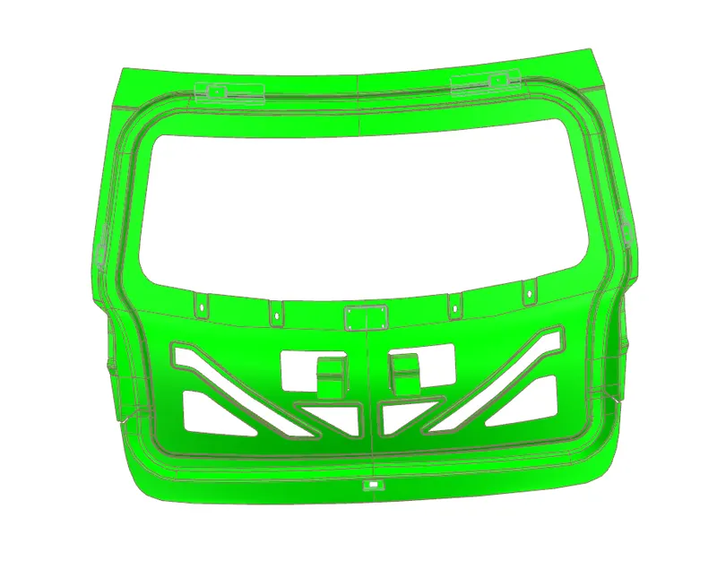
- In order to make sure the drawing of inner panel body is proper; we do draft analysis. We need to define the drawing direction and select the inner panel body. We take limit angle as 5 degrees.
- Portions that require different manufacturing method, or are not in the direction of drawing may not be considered in draft analysis results.
CONCLUSION:
Car back door was designed using the given styling surface, and under provided design regulations.