Design of backdoor
Design of backdoor
AIM:- To develop the car backdoor by using given surface method by automotive sheet metal design.
SOFTWARE USED:- Siemens NX CAD (Unigraphics)
BACKDOOR:-
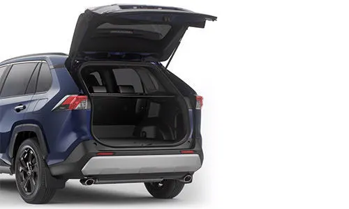
A backdoor is located at the rear end of the car which gives access for the boot space to store luggage.,spare whhel etc.These doors can be operated mannualy or eclectric powered.In most of the luxuary car is electric powered.
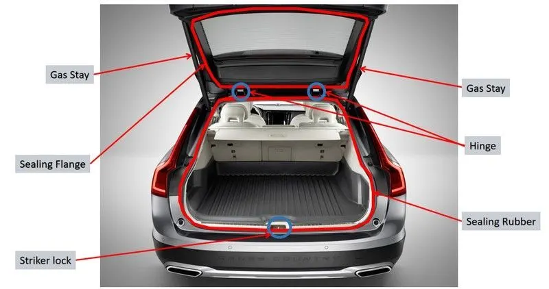
Back Door also called as 'Hatch', or 'Tailgate', 'Trunk-lid', 'Boot-door' is basically the 5 door in a 4-door car. It's the rearmost part of the vehicle which gives access to the trunk and has mounts for wiper motor, tail lamps, hinges for supporting its weight in opened position, gas stays which help with its opening and keeping it open, radars and cameras etc.
Major Parts and Reinforcements:- The backdoor consists of the following basic components:
-
Backdoor Outer Panel (Upper)
-
Backdoor Outer Panel (Lower)
-
Backdoor Inner Panel
-
Hinge Reinforcements (LH & RH)
-
Gas-Stay Reinforcements (LH & RH)
-
Latch and Striker Reinforcement
-
Wiper motor Reinforcement
TAILGATE:-
Tailgate is a door at the back of a truck or car, that is hinged at the bottom so that it open downwards.
DESIGN INTENT:-
The intent of the project is to design a Body In White Back Door of the vehicle considering the engineering standards and manufacturing requirements which satisfies the Deep Drawing Process.
DESIGN CONSIDERATION OF A BACKDOOR:-
-
Functional Requirement of Hinge and gas stay
-
Rear visibility criteria
-
Luggage volume
-
Crash Analysis
-
Bend Test, Dent Test, Torsion Test & Endurance Test
-
Rear Crash Regulation
-
Gap and flushness Requirements
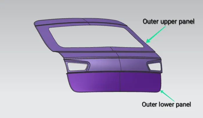
DESIGN OF BACKDOOR OUTER PANEL:- The Outer Panel is the styling surface of the back door. Other components of the backdoor are designed with reference to the outer panel. It acts as the outer cover and deals with the aesthetics of the car.
In this design outer panel is divided into two parts
-
Outer Upper Panel
-
Outer Lower Panel
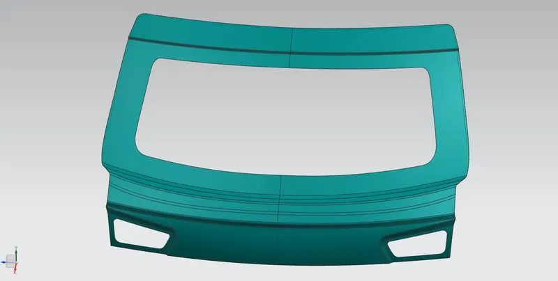
Outer Upper Panel:-
- The Outer Upper Panel Extracted from a styling surface.
- The panel is altered for the required design with the surface tools of NX CAD
- The thickness provided for the outer panel is 0.75 mm
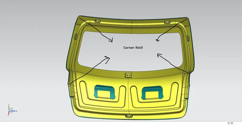
- Hemming is provided with the corner relief.
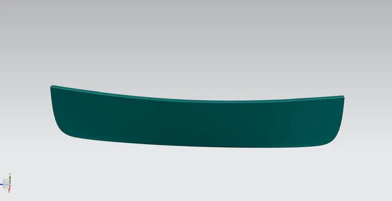
Outer Lower Panel:-
- The Outer Upper Panel Extracted from a styling surface.
- The panel is altered for the required design with the surface tools of NX CAD
- The thickness provided for the outer panel is 0.75 mm
- Hemming is provided with the corner relief.
Outer Upper & Lower Panel:-
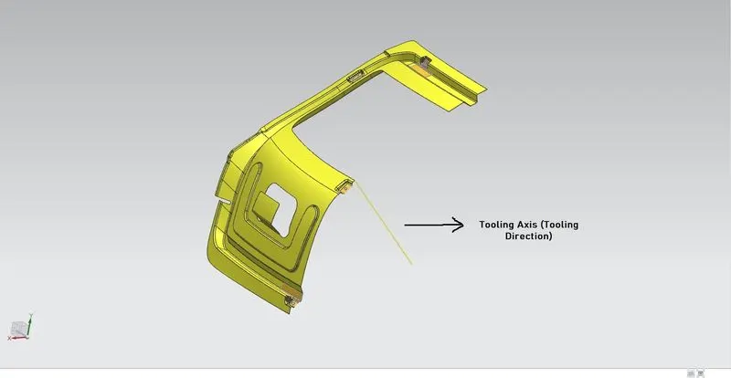
Tooling Direction:-
-
Before starting to design the inner panel of the back door the tooling direction for Deep Drawing purpose should be created.
-
Then the styling surface needs to be checked and analyzed since it might have irregularities, hence it must be fixed first.
-
Then the back door was designed using the top-down approach.
DESIGN OF BACKDOOR INNER PANEL:-
- The Inner Panel Extracted from a styling surface.
- The panel is altered for the required design with the surface tools of NX CAD
- The thickness provided for the outer panel is 0.75 mm
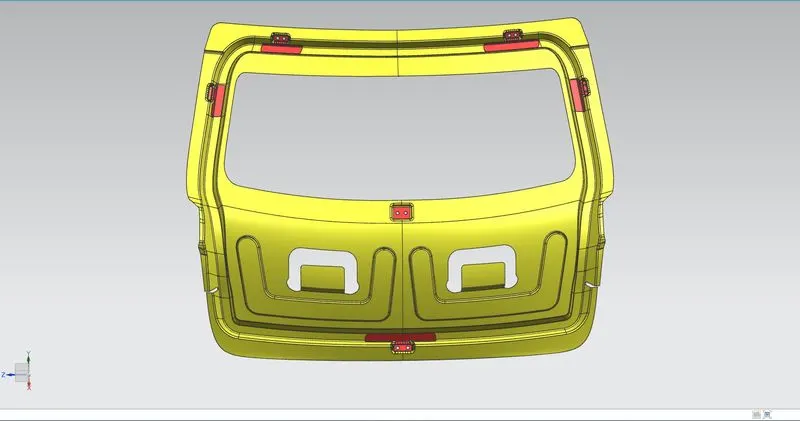
After creating the tooling direction the design of the inner panel will begin where we will first develop an effective sealing flange by checking all the boundaries and by following the shape of the inner panel design. By creating multiple flanges and by using surface modeling techniques the concept design of the inner panel was created.
-
After the concept of the inner panel is developed, then the child components like a hinge, latch, gas-stay locations, and their reinforcements must be designed. Which completes the overall design of the tailgate.
-
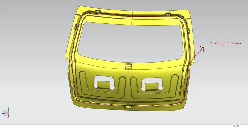
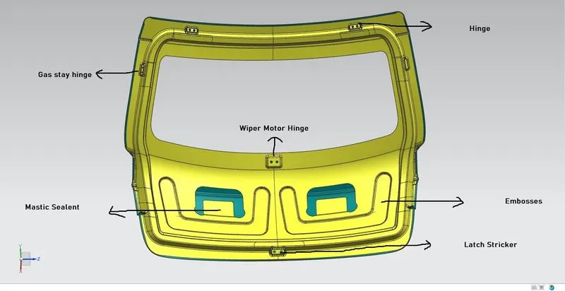
The embosses were created in ‘V-Shape or Y-Shape’ so that if the vehicle undergoes the crash then the force dissipates over it which reduces the damage transferred to the trunk space.
 3
3
MASTIC SEALANT:-
The mastic sealant is used to fix the inner panel with the outer panel which increases the NVH factor and stiffness of the back door.
HINGE, GAS STAY & WIPER MOTOR EMBOSS:-
The Orange circle denotes the hinge emboss which was created using the datum plane and emboss feature in NX. It was also designed in a way that the emboss should have a flat surface for assembling the hinges using it.
The violet circle denotes the gas stay emboss which was created using the surface of the connecting flange.
The yellow circle denotes the Wiper motor emboss which was created using the surface of the connecting flange.
LATCH AND STRIKER EMBOSS:-
The Latch and Striker emboss were designed by creating a trajectory that follows the opening and closing of the back door with respect to the hinge axis.
STRIKER POSITION:-
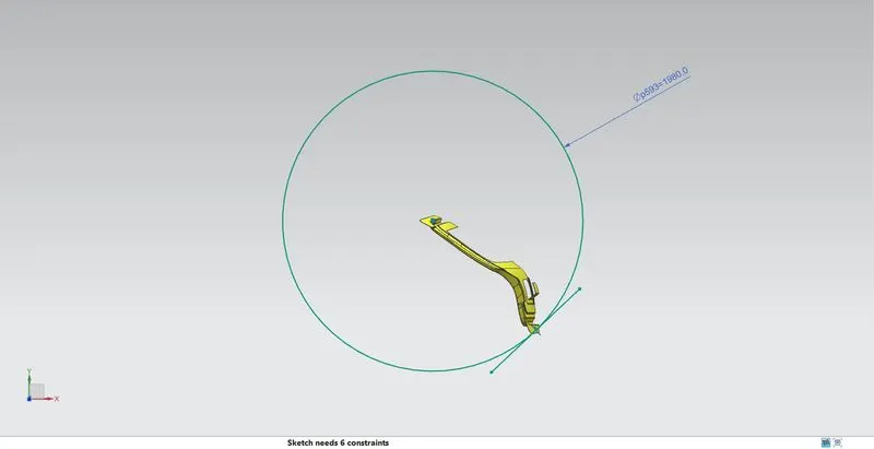
The position of the hinge should be perpendicular to the latch when the latch and striker meets. The circle is drawn from the center of the hinge axis to find the path of the striker and positioned perpendicular to the path.
DRAFT ANALYSIS:-
-
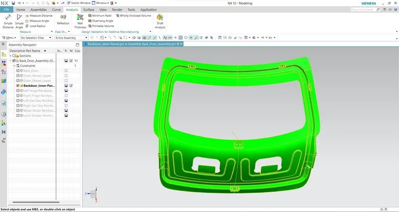
The draft analysis will be performed for the tooling direction created at first and checked that the model is suitable for manufacturing.
-
Then to get a complete green portion the necessary changes to the draft angle of the embosses were carried out by optimizing the model.
-
The Draft Analysis command enables us to detect that the part drafted will be easily removed or not.
-
This type of analysis is performed based on color ranges identifying zones on the analyzed element where the deviation from the draft direction at any point, corresponds to specified values.
HEMMING:-
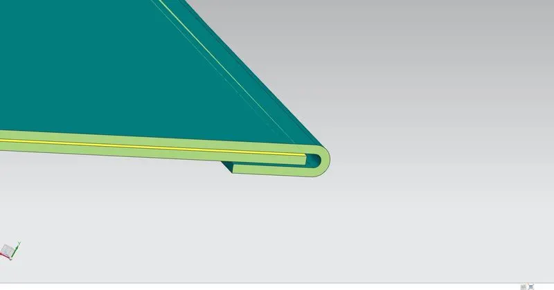
Hemming and seaming are two similar metalworking processes in which a sheet metal edge is rolled over onto itself. Hemming is the process in which the edge is rolled flush to itself.
-
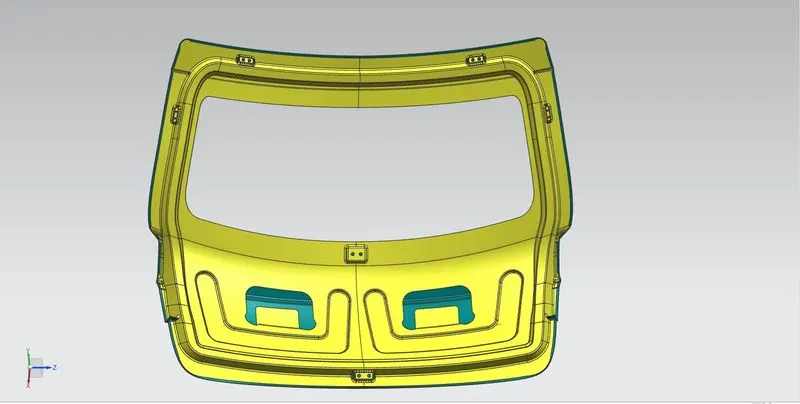
The outer panel was designed as two separate parts named as outer panel upper and outer panel lower.
-
After designing the outer panel the Hemming was created by offsetting the surface with the help of face blend and swept surface.
-
The two separate outer panels will be joined using Blanking
CORNER RELIEF:-
During the hemming process, when giving the Corner Relief helps to control sheet metal material behavior and to prevent unwanted deformation during unbend operations and also helps to reduce the number of passes in hemming.
DESIGNING THE REINFORCEMENTS:-
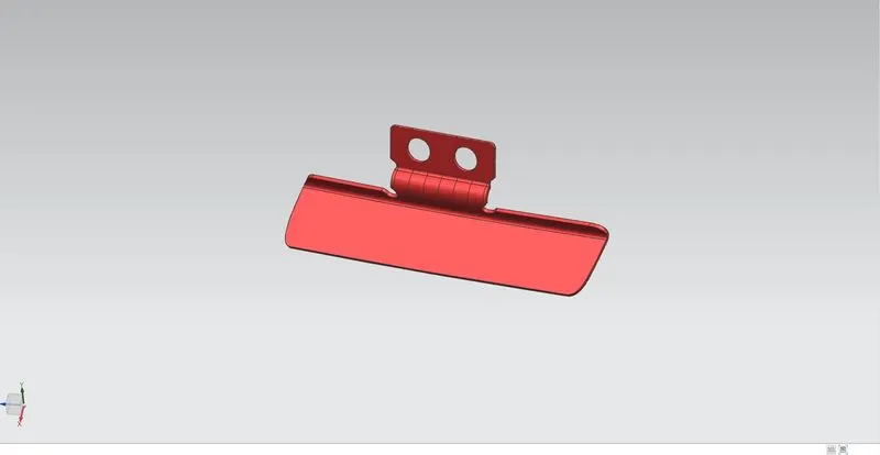
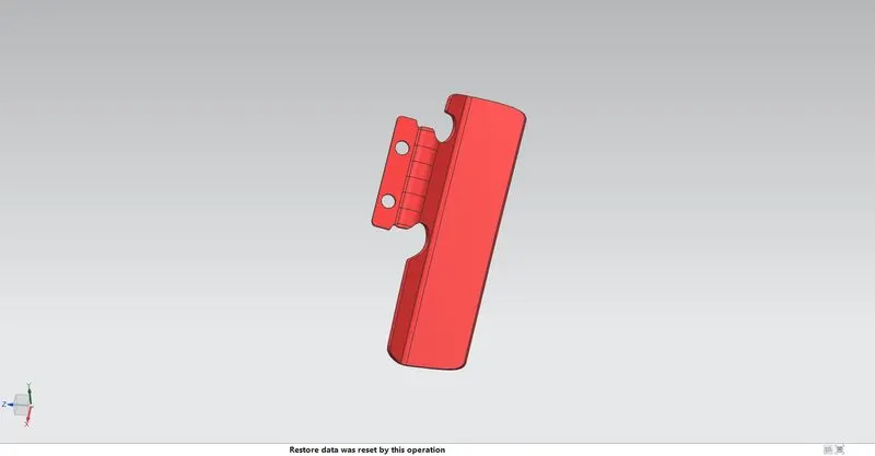
The thickness provided for all reinforcements is 1.5 mm.
-
HINGE REINFORCEMENT
-
GAS STAY REINFORCEMENT
-
WIPER MOTOR REINFORCEMENT
-
LATCH REINFORCEMENT
All the reinforcements were created using the same method, first, the linked body was created separately for each with the help of extract geometry and then the required portion was trimmed out and then thickened.
Hinge reinforcement:-
Hinges enable the opening and closing of the back door. One end of the hinge is fixed on the backdoor and the other end on the Roof, on both sides. Hinges can be placed outside or inside the backdoor.
The hinge reinforcements are added to compensate for the weak region due to the acting load over it.
Gas Stay Reinforcement:-
Gas Stay is a device used for supporting the back door in its open position. Gas stay requires no manpower and is engaged into support position automatically as the back door opens. One end of the Gas Stay is fixed on the backdoor and the other end on the Body Side or on the Back door stationary area.
Embossing is provided at the Gas Stay mounting area to compensate for weakness and improve strength.
Wiper Motor Reinforcement:-
Wiper motor reinforcement is created to mount the wiper motor assembly.
Latch and Striker Reinforcement:-
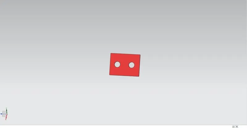
The Latch & Striker forms the locking mechanism of the backdoor with the car. Due to regular opening, closing, and over slamming of the backdoor, there is stress developed in the Latch and Striker area. To compensate for the same, reinforcements are added in this area.
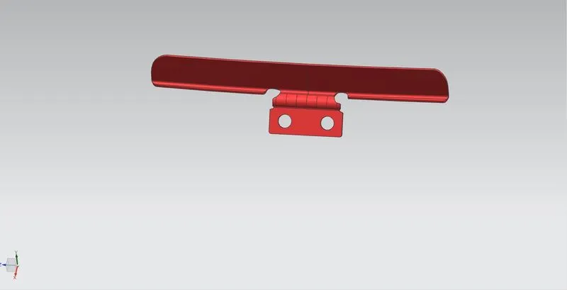
All Reinforcement in this image which is given below:-
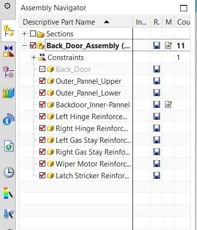
Tree Structure:-
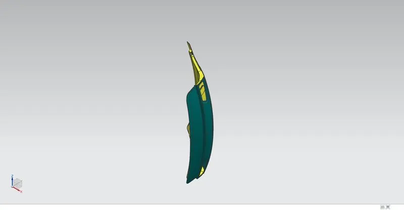
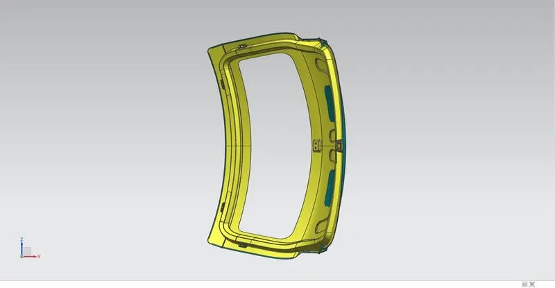
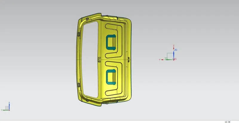
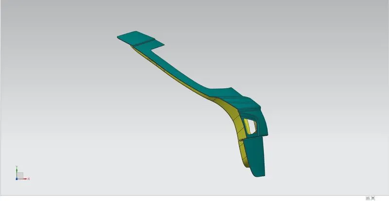
All views:-
Isometric view:-
Front view:-
Side view:-
Top view:-
CONCLUSION:-
Thus the Body In White Back Door of a car was designed following the engineering standards and also the deep drawing requirements were satisfied.