Design of backdoor
Report On Backdoor Design
Aim: To create backdoor design from the given class A surface and adding reinforcements and emboss, finally perform the draft analysis on it.
Note: This design is performed on the NX CAD stdent edition.
Step 1: Modifying the class A surface, given class A surface has lot of gap between the surface to get rid of them we apply:
- Through curve mesh command by selecting the edges as primary curve and bridge curve as cross.
- on the surface with blends we remove them if there are any irregularity then apply the through curve mesh.
- To apply blends between two surface wherever required we apply face blend by selecting the two surfaces.
- There is also two overlaping surface in the given Class A, so by trim then with offset on curve and joining them by through curve mesh we get rid of them as well.
- Finally extending the projected walls on the given Class A surface to meet the requirement of spot welding i.e., min. 10mm.
- Our modified class A surface will look like this:
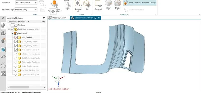
Step 2: Seperate Outer panel into two part files naming outer panel upper and outer panel lower, then create another file naming inner panel to start working on the inner panel as shown:
- We start constructing inner panel by the sealing flange first, which can be done by offseting the outer panel by 1.7 mm both outer and lower portion and trim those strip surfaces by creating offset on curve ensuring that there should be a smooth curve.
- We create these strip surfaces by the help of through curve mesh taking bridge curves and in the lower panel we contruct a sketch then trimming it to create the surface.
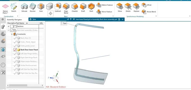
- Finally Sew each surface to create the sealing flange bottom surface our surface gonna look like this:
- Then we created the side wall of sealing flange by the help of law extension command and joined the lower inner panel with upper by the help of swept gave the blend radius with kekeping the minimum radius 3+thickness mm in mind.
- Also we trim and extend surface with these one wall surface, then we sewed these surfaces our design will look like this:
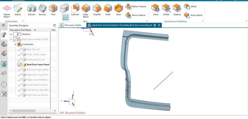
- Now we create inside flange for the sealing flange which is also called wind sheild flange by the same process like law extension with tooling direction and trimming this law extension with the working surface or reference surface, gave the blend radius of 4mm to avoid the sharp edges.
- Then we created the half closed surface with the through curve mesh command taking the bridge curve as cross curve finally sewing them to create the surface, also released the tension of these bridge curve to avoid intersection with the outer flange our created surface goona look like this:
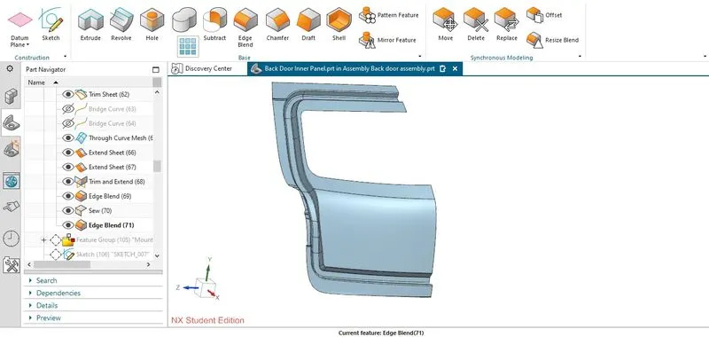
- Our sealing flange is complete, now we move on to create the mountings and emboss on the above surface, by creating sketch on the bottom surface and trimming it to create the cutout then creating law extension with keeping the minimum draft of 7 deg, in the mind. Basically we are going to attach masting sealant on this surface so we give gap of 5 mm between the flange and the outer surface.
- The length of this flange is taken in such a way that we ensure that only cutout material is used for this flange, no extra material added. Also to give blend on the sharp edges we created reliefs on the corner at the bottom.
- Now We trim this flange with offseted surface of reference surface of 5mm our design will look like this:
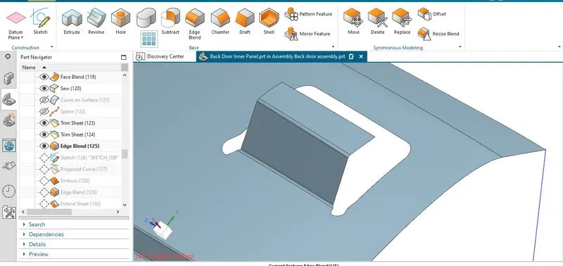
- Now we move onto emboss to add the strength to our design, then gave blend of 4mm on its shrp edges then mirrored this whole design what we created till now with reference to the datum plane, before this mirroring we gave extend sheet and trim sheet to ensure proper sewing between mirrored and original surface.
- Also a general point we taken is the we checked our design after every 10-15 min with thicken surfcae command for verification.
- Now We created the emboss for the gas stay and hinge mountings by creating datum plane on the desired curve on the edge and creating datum plane first then created one slanted line with taking that datum plane as a reference used law extension on that sketch to create symetric surface and then removed the sharpcorner by offseting the curve around the surface and trimming it, then again gave the law extension along the tooling direction with taking minimum draft angle of 7 deg of the walls of emboss, then finally used trim and extend to create the emboss on inner flange and gave the blend radius of 4 mm to avoid the sharp corner. and created holes with giving clearance of 5 mm around it to the near surface. In this way we created emboss for each montings.
- Our Final surface gonna look like this:
-
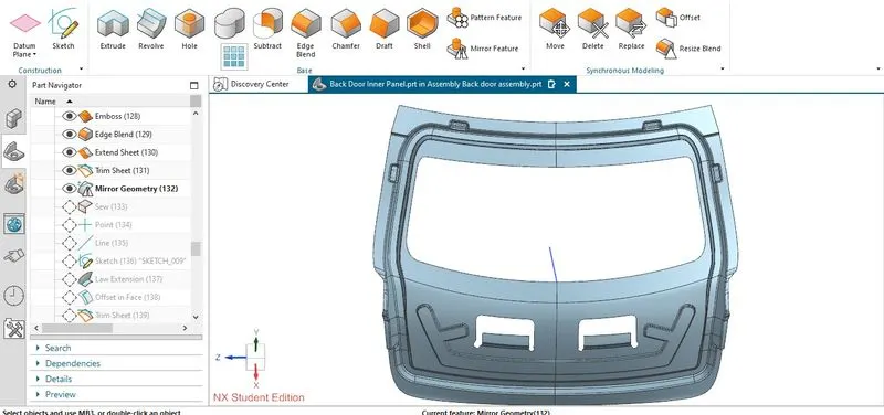
- Now we create emboss for latch striker, by first creating hinge axis between the holes of hinge mountings and creating the trajectory circle of that latch stiker by taking the mid point of the hinge axis as the centre point of circle and intersecting that circle at the bottom of our inner panel surface, now create tangent line on that circle, then create another line which is perpendicular to that tangent line that line would be used as a sketch for creating the latch striker emboss, the process would bes same as we did for creating the emboss mountings of hinge and gas stay, we give blends with radius of 4 mm to avoid the sharp corner.
- Then we created the wiper motor emboss by creating the datum plane first and creating the sketch on that datum plane, now we do the same process as we did in the past to create other emboss mountings the wiper motor.
- Our final design gonna look like this:
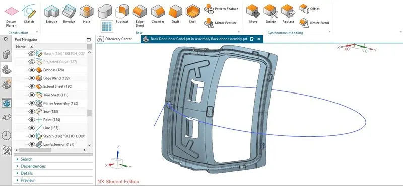
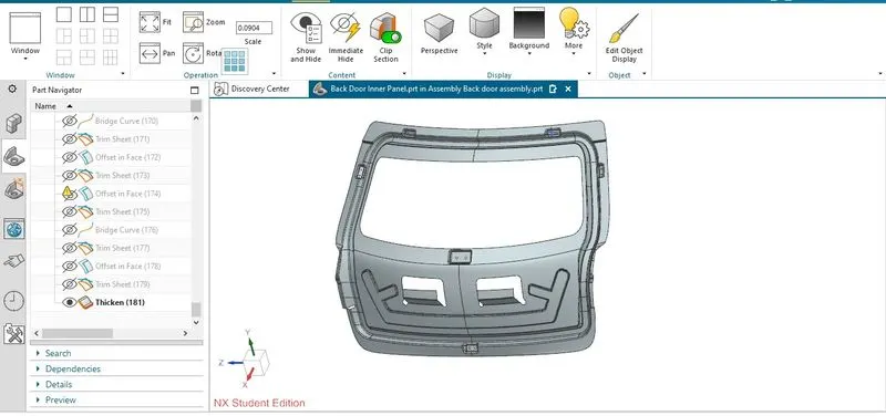
- Now finally thicken the created surface by thickness of 0.75 mm our solid surface gonna look like this:
Step 3: Now we move on to create hemming surface for the outer panel , we first created the hemming surface for the upper portion as shown:
- We first removed the sharp corner of the upper surface by trimming it with the bridge curve, the created the offset curve at distance of 8mm and trimmed it with the reference surfcae then offseted that reference hemming surface at a distance of 2.65 mm.
- Then used law extension between that stripped hemming surface and the working surface perpendicular to the working surface, then give the three face blend to get the foldedd surface, Also we need should ensure there should be relief around the corner of hemming surface to avoid the irregularities in the manufacturing process.
- Now we mirrored this geometry by taking datum plane as reference ensuring that there should be no gap during the sew between original and the mirrored surface by the command trim sheet and extend sheet.
- Then finally thicken that whole surface which look like this:
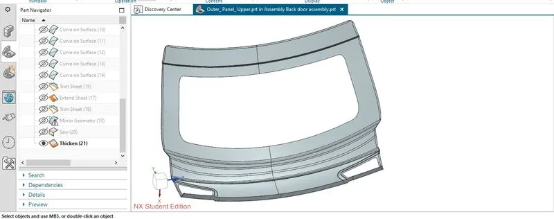
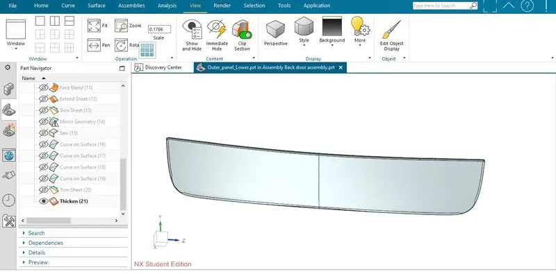
- Now we create the hemming surface for the lower portion of the outer panel by the same process as we did for the upper portion, and created the reliefs in that portion also and thickened the final surface such that it gonna look like this:
Step 4: Now create reinforcements for the both hinges, gas stays , wiper motor and latch striker to add strength, we create them by taking reqired surfaces from the inner pannel by the help of wave geometry linker.
- We trim it to short by the bridge curve and curve on the surface, ensuring that there should be no sharp corner and gave relief to avoid the same, finally gave thickness of 1.5mm . In this way we created reinforcements for left side and right side hinges and gas stayes.
- For the wiper motor and striker reinforcements we simply worked on single surface which is at the bottom and thicked it to 1.5 mm.
- Our final design will look like this:
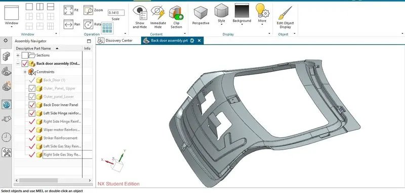

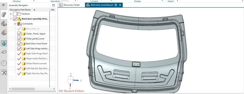
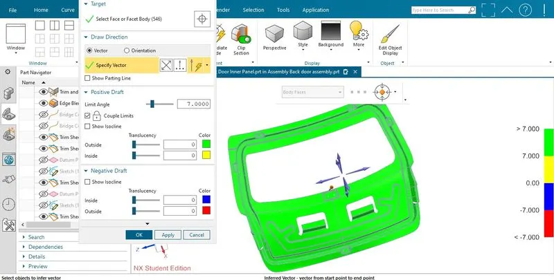
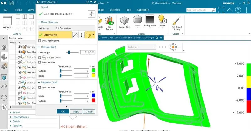
- Draft analysis performed on the design with considering that minimum 7 deg. taking as clearance angle as shown: