Cyclone Separator Challenge
CYCLONE SEPARATOR
AIM :
To Perform the analysis of cyclone separator by using different particle diameters and velocities
OBJECTIVE :
The four empherical models used for the cyclone separator efficiency are
Cyclones are devices that employ a centrifugal force generated by a spinning gas stream to separate particles from the carrier gas .their simple design ,low capital cost and nearly maintenance-free operation make them ideal for use as pre-cleaners for more expensive final control devices such as bag houses or electrostatic precipitators
CYCLONE EFFICIENCY EMPIRICAL MODELS -
- IOZIA AND LEITH MODEL
Iozia and Leith logistic model is a modified version of barth model,which is developed based on force balance .the model assumes that aparticle carried by the vortex endures the influence of two forces ,a centrifugal force and a flow resistance .
- LI AND WANG MODEL :
The Li and wang model includes particles bounce or re-entrainment and turbulent diffusion at the cyclone wall .Atwo dimensinal analytical expression of particle distribution in the cyclone is obtained .Li and wang model was developed based on the following assumptions .
- the radial particle velocity and the radial concentration profile are not constant for uncontrolled particles with the cyclone
- Boundary conditions with the considerations of turbulence diffusion and particle bounce re-enter on the cyclone wall
- KOCH ADN LICHT MODEL :
Koch and licht collection theory recognised the inherently turbuence nature of the cyclones and the distribution of gas residence times within the cyclone .koch and licht described partice motion in the entry and collection regions with the additional follwoing assumptions :
- the tangential velocity of a particle is equal to the tangential velocity of the gas flow ,there is no slip in the tangential direction between the particle and the gas
- the tangential velocity is related to the radius of the cyclone
- LAPPLE MODEL :
Lapple model was developed based o force balance without considering the flow resistance .Lapple assumed that a particle entering the cyclone is evenly distributed across the inlet opening .The particle that travels from inlet half width to the walls in the cyclone is collected with 50% Efficiency
PROCEDURE FOR THE SIMUALTION PROCESS :
GEOMETRY :
Import the geometry into the spaceclaim ,and then extract the volume of the component ,as we are going to simulate the fluid volume of the component and after that supress the thickness of the component for not causing error during the soltuion process after the volume extraction then close the space claim
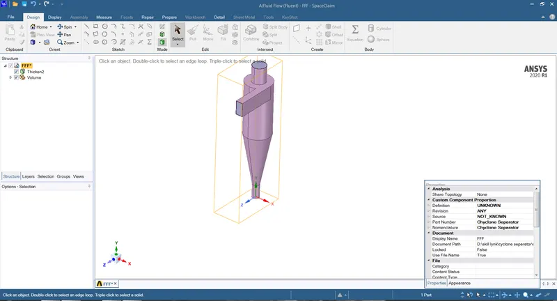
without the volume extraction
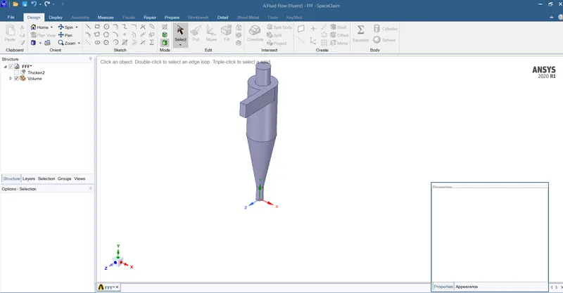
after the volume extraction
MESH :
And then open mesh for mesh generation ,inorder to get the accuarte results use the cut cell mesh for the process.select the assembly modeling in their select the cut cell mesh and then genarate the mesh after that give the name section as INLET ,OUTLET-1 ,OUTLET-2
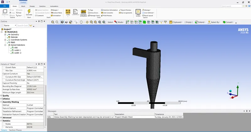
Cut cell mesh
SOLUTION PROCESS :
- After the mesh genaration ,then go for the solution process
- Select the k-epslion model ,RNG for the following process inorder to get accurate results
- click on the descrete model in that select the contineous process ,as we are using the model of contineous flow particles ,and mostly we use these kind of separators only and after that select the select the inlet ,and then create particle diameter as 3 and 5 and velocity as 3 m/s and 5m/s click ok
- And after that allot the boundary conditions,and INLET -REFLECT ,WALL -REFLECT ,OUTLET -1 -ESCAPE ,OUTLET -2 -TRAP
- And then click on the solution methods ,compute from -inlet and then use standard intialization after that run caluclation ,after the caluclation complete then export the particle data and then we can get the data how many are trapped ,incomplete ,and escaped
- And now the the following figures show the process
3m/s -3micrometer diameter
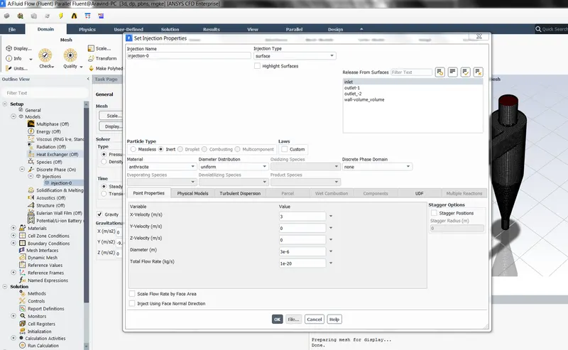
injection properties
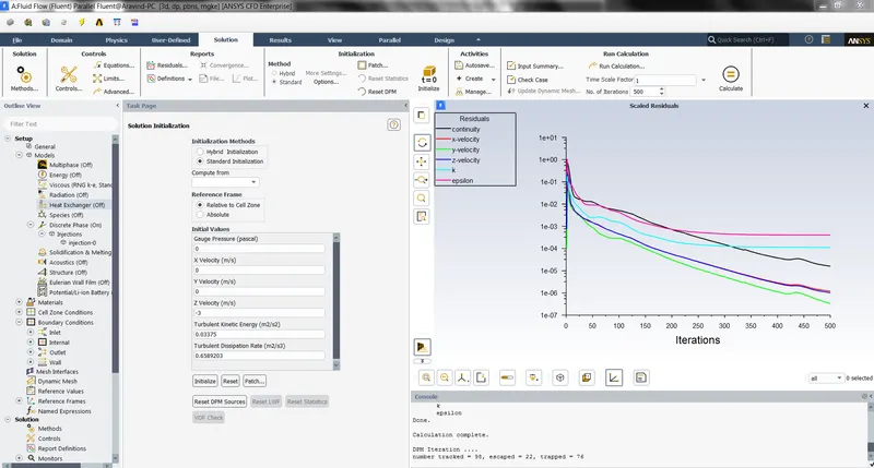
residuals
DPM ITERATIONS
TOTAL NUMBER TRACKED :98
TRAPPED :76
ESCAPED :22
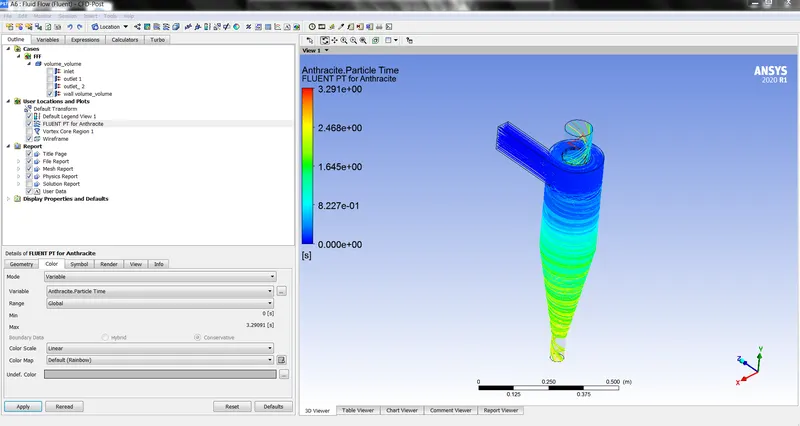
Anthracite Particle time
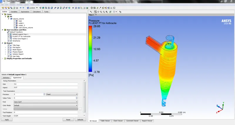
Pressure
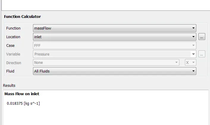
mass flow inlet
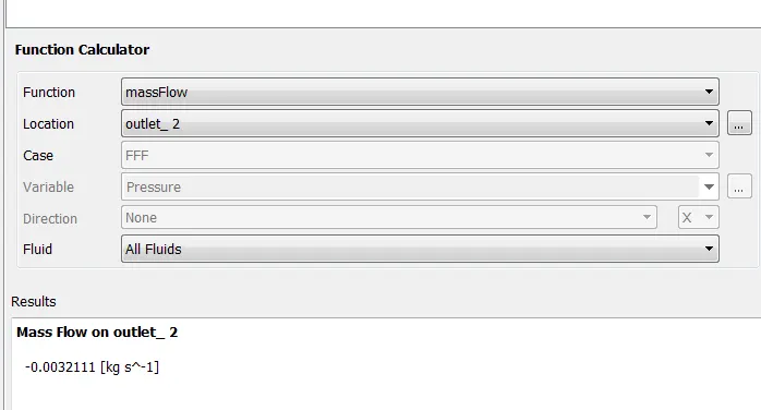
mass flow outlet -2
5 m/s -5micrometer diameter
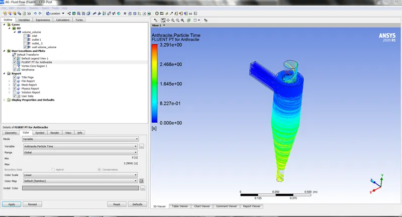
Anthracite Particle time
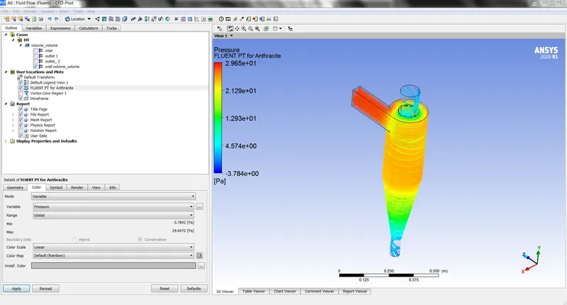
Pressure
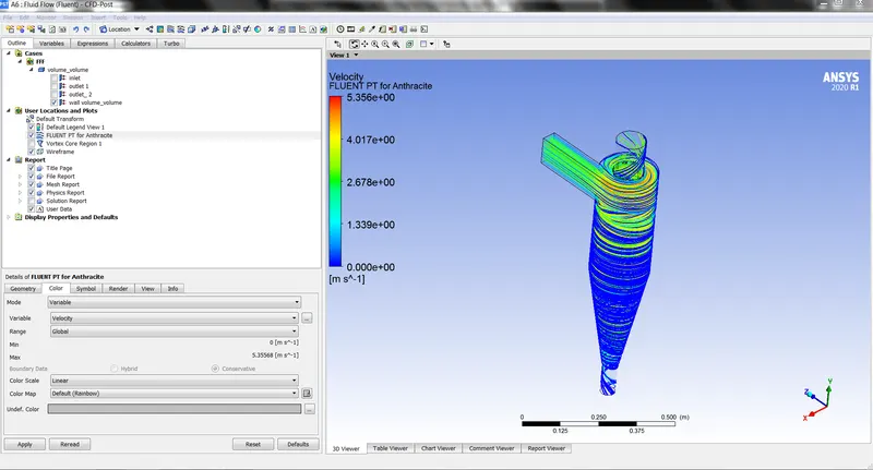
velocity
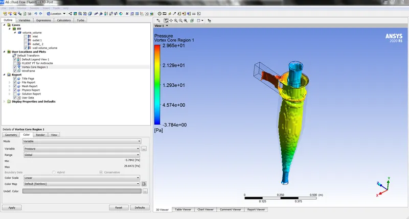
vortex core Pressure
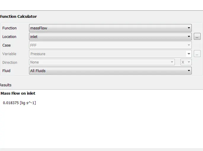
mass flow inlet
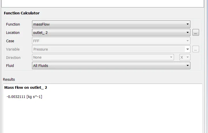
mass flow outlet -2
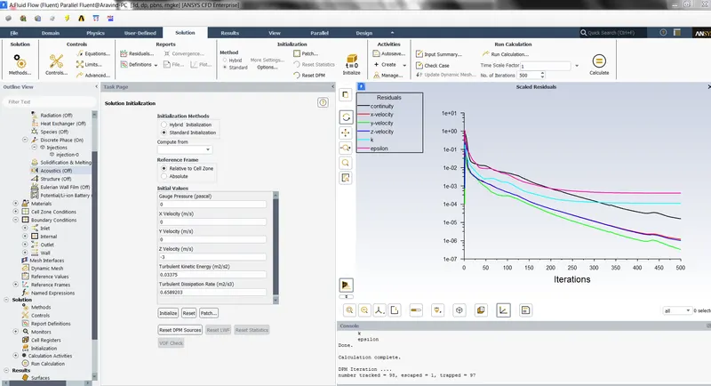
NUMBERS TRACKED -98
TRAPPED -97
ESCAPED -1
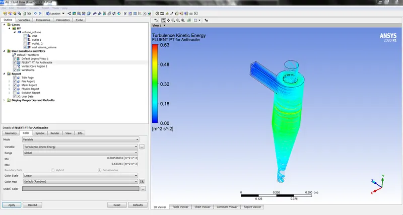
These are the solution figures ,that shows the solution process and the results
CONCLUSON :
- From the above results ,we can conclude that if we increase the size of the particles ,then there will be more particles trapped in the wall of the component and the particles that are going to escape is less from the separatoe is less .
- And the particles with less diameter ,22 of them are escaped and 76 of them are trapped
- By this the particles having more diameter can be trapped in the wall ,as main factor that they have more wieght as compared to the particles with less weight .so there is a maximum possiblity increasing the size of the particles ,we can prevent the particles from escaping .