Ahmed Body Challenge
AHMED BODY
AIM :
To find out the flow simulation over the Ahmed body and to see the velocity and pressure ove rthe ahmed body
INTRODUCTION:
AHMED BODY is a simplified car model.it is done because the flow over the ahmed body shows the essential flow features around an automobile.mostly the ahmed body simulation process is used for the passengers cars .these simulation process helps to compare with the practical or experimental .
In this simulation process we are going to simulate by using different mesh refines and to see the results of the by using different meshes.
PRE-PROCESSING:
- GEOMETRY
IN the geometry ,we are going to either create the geometry or modify the geometry .click on the ansys fluent and after the options are available ,click on the geometry the go the space claim ,and then go the file and then import the file that have been saved in the downloads .And if we want ot change the units go the space claim options an dthen change the units either to the metres or mm.
After the component has opened in the spaceclaim window then ,click on the enclosure option .the purpose of the enclose the component either by creating the box or cylinder,by using this we can get the accurate values .
And after that click on the plane ,select the origin point .and after that then the select the plane in the required direction and click on the cut section view by selecting the required plane sectional view and by that we acn see the half sectional view of the ahmed body and after that close the spaceclaim window then go to the mesh .
- MESH
Now in this mesh section we are going to use two different mesh sizes to see difference in the results (coarse and fine mesh )
Coarse mesh
after closing the space claim then go the mesh in order to do the mesh genaration .after the component available in the meshing process ,generate the mesh and see how it looks like . and by clicking the section plane we can see the ahmed body how the mesh is inside of it .and if the mesh generation takes place in the ahmed body the again go the space claim and click on the extrude component to supress for the physics and then go the mesh and clear the generated data then again generate the mesh ,then the ahmed body won't contain mesh .click on the mesh, go the element in that element sizing give 0.08m then go the sizing inthat give the max sizing 80 and then generate mesh .and then click on the inflation layer select the required edge and then apply and then generate mesh .and give the named sections to the component .and we use multizone method
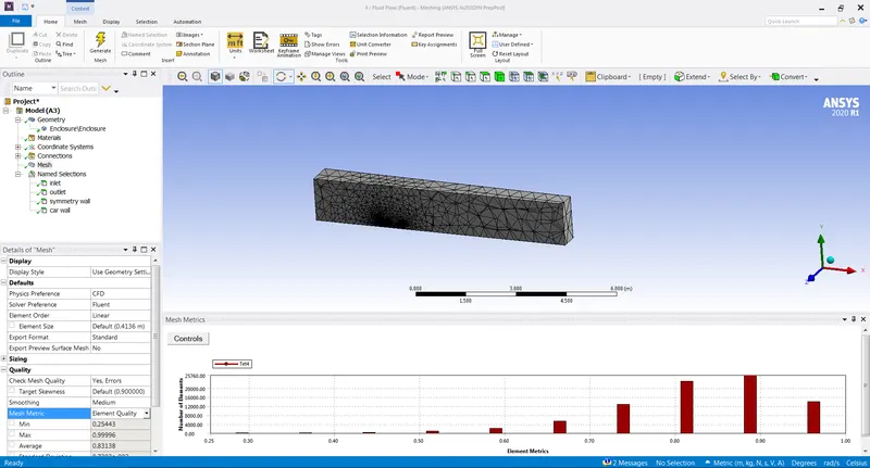
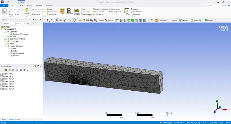
And after creating the mesh then check the mesh quality of the component and after checking the mesh then update the mesh .
REFINED MESH
In the refined mesh we are going to decrease the size of the element for getting the better results ,in order to do that we are going to create another box for the ahmed body in the spaceclaim and repeating the same process as before one .in this we are going to use the element size as 0.06m and generating the mesh upadate it .nodes 185158 elements 696428
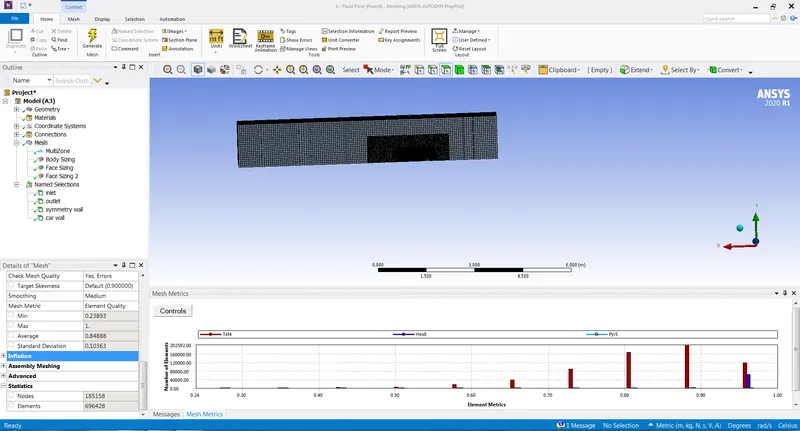
And after creating the mesh then check the mesh quality of the component and after checking the mesh then update the mesh .
SOLVING PROCESS
In this solving process we are going to apply the boundary conditions and material and other required conditions for the process to get the required results
After the meshing completed ,then go the solution process after after going in to the solution process check mesh quality agian and use the pressure based solver and after that give the boundary conditions as inlet velocity as 25m/s and other . and add the material and after all this go the definitions and add drag and lift plots to the simualtion process and add the reference values to the component and do the hybrid intialization and then go the go the results add the velocity contour plot and also add the aniamtion and after that caluclate it by giving the number of iterations to it .after the caluclation is complete then go to the post processing process
POST PROCESSING PROCESS
COARSE MESH RESULTS
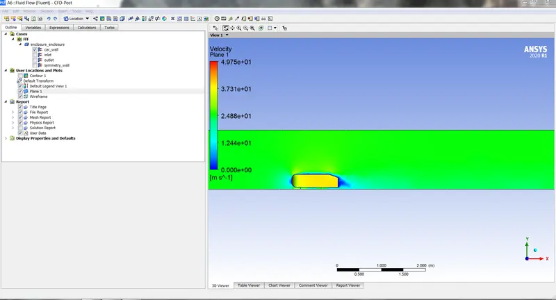
VELOCITY PLOT
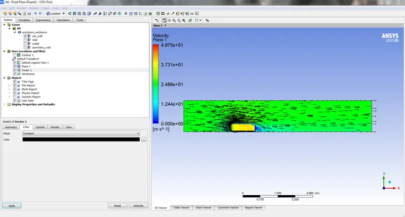
VELOCITY PLOT WITH VECTOR
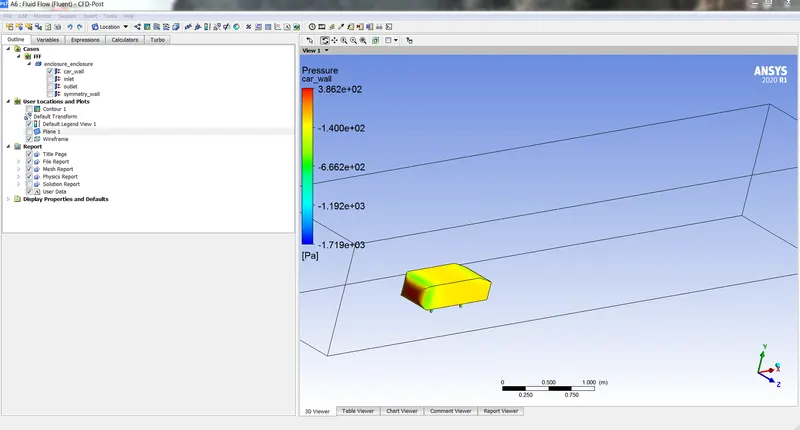
PRESSURE PLOT
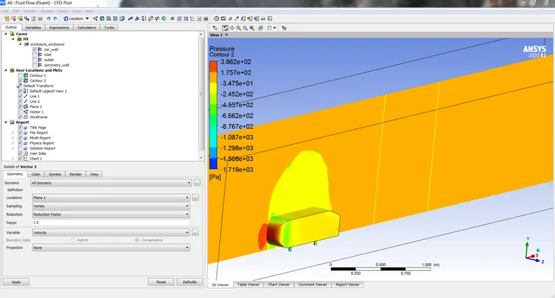
PRESSURE PLOT (AT MID PLANE )
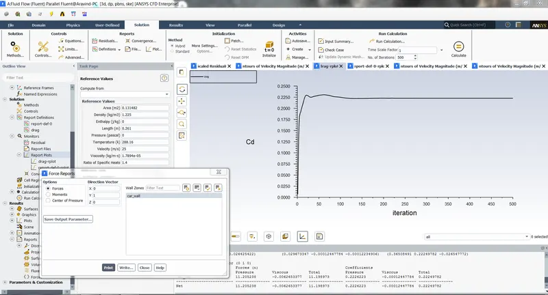
DRAG PLOT
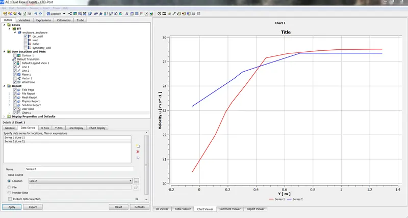
CHART
As shown the following results as for the coarse mesh
as we above the drag plot we got 0.22 ,so it is good where the drag is minimum as per our results we got .
ans also the pressure ansd velocity plots shows the velocity and pressure over the ahmed body.
FINE MESH RESULTS:
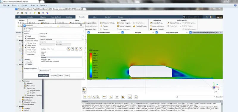
veloctiy plot -1
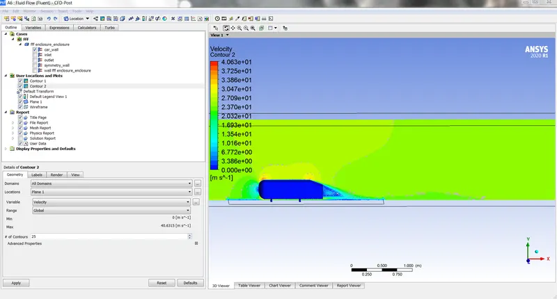
velocity plot -2
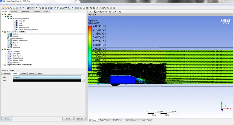
velocity plot with vector
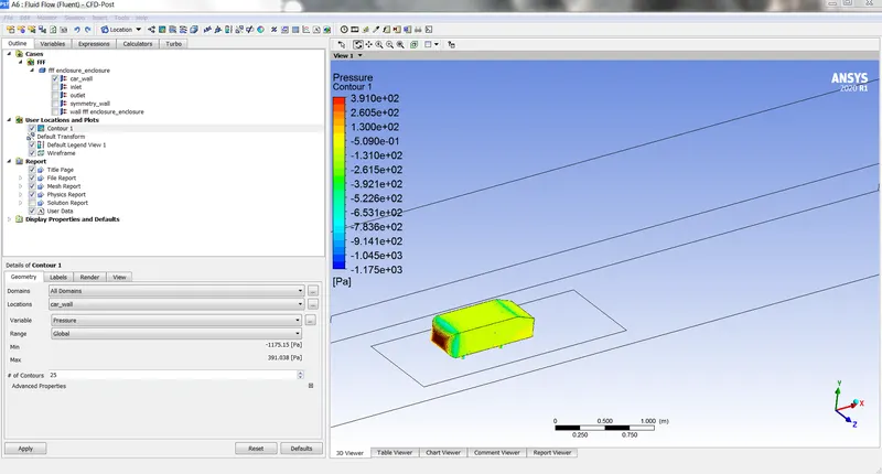
pressure plot
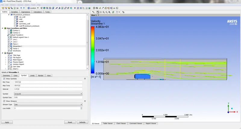
velocity with stream line
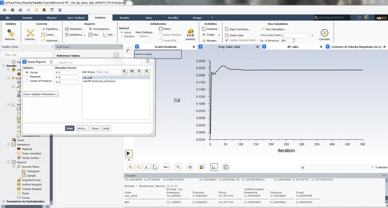
drag plot
In the drag we got {0.28}
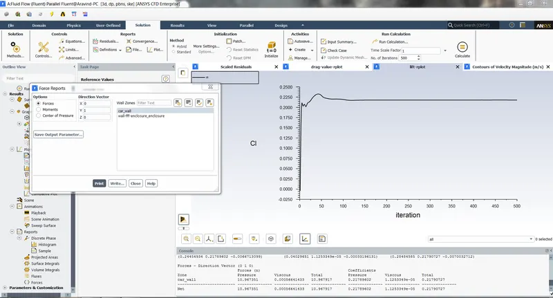
lift plot ,we got {0.21}
from the above following figures shows all the results velocity ,pressure ,drag and lift.
and we can we see that from the drag and lift plot we got better results as per our given conditions and the velocity plot shows where the max and mini and the pressure plot shows where the max pressure and negative pressure is .
question and answers
- A AHMED BODY is a like square body that which is the simlified model of the car body ,its just looks like a squre with having bottom two legs on it . the ahmed body waas first created by S.R.AHMED in his research some slient features of the time averaged grounf vehicle wake in 1984 .the area of the ahmed body is 0.261m the importance of the ahmed body ,is that which is a simplified car,and that which allow for the accurate flow simulation over it to see how the flow is it .it is one of the important one that many people do the aerodynamics how the air flow on it that to see the drag and lift ,and compare their numerical models to the experimental data .this ahmed body simlulation ismost commonly used for the passengers vehicles .some of the characterstics that can be obtained from the ahmed body is velocity,pressure ,drag force ,lift force and wake region
- there are many reasons that pressure goes negative ,the neagtive pressure says that where the pressure is smaller then the other region .when velocity increases the pressure decreases, due to this when the when the veloctiy over the ahmed body increases the pressure begins to drops and so on the decreasing and so the pressure at the wake region becomes too negative at that region .and not only that to over come the shear stress the pressure could also become negative and due to flow circulation
- the point of separation is where the air flow gets separate when it hits the ahmed body and this point of separation also leads to pressure drop of the body .
the grid dependency test helps us to see the wake region more clearly and also by making mesh more finer (by increaseing the elements )we have seen see the the results more clearly
And finally we can conclude that by using the finer mesh we get the accurate results and in the smoother way.