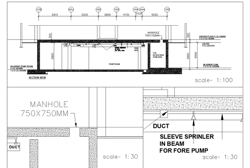
Creation of Multiple viewports, Scaling the drawing and setting in Template in AutoCad
1. ) LAYOUT OF THE PLAN AND SECTION A OF THE PROJECT IN CHALLENGE 7 :
A ) AIM & INTRODUCTION:
AIM :
- To create the layout of the plan and section A of the project in challenge 7, using the template Tutorial-mArch.dwt in a page layout as per the given Figure.
- To create the viewport of the size as shown in Figure by using the MV command .
- To edit the attibutes in the title block by ATTEDIT command.
- To create the A1 sized page layout and to plot it.
INTRODUCTION:
- It is to create the pagespace layout from the modelspace layout of the plan and the section A, which was either created or opened from the challenge 7.
- The required templates can be attached in the pagespace layout from the worksheet folder.
- The ATTRIBUTES in the template blocks can be edited as per required values.
- The viewport will be created in the pagespace layout as per the given figure.
- The layout of the plan and section A will be displayed in the viewport which was created in the pagelayout.
- Here, A1 pagesized layout is used to create the viewport and then it will be ploted.
B ) PROCEDURE:
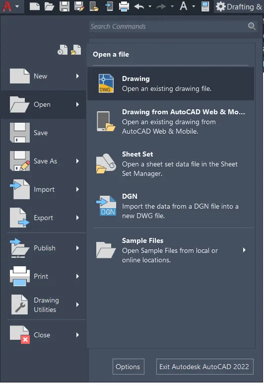
- The layout of the plan and section A has to be created or opened from the saved challenge 7 through a Main menu bar<Open<Challenge 7.
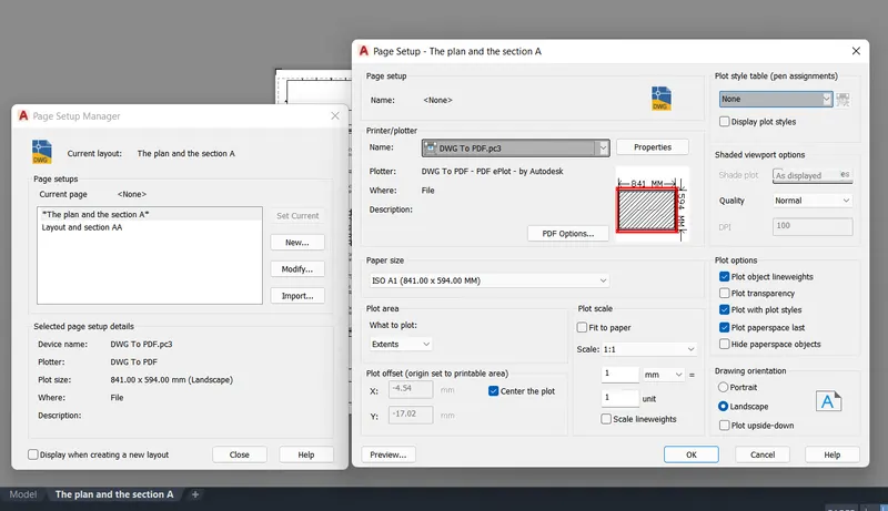
- Create the named view of the drawing which can be viewed in the viewport window if created, by selecting a name of the view from Title bar<View<Viewport manager and selecting plot as dwg to pdf and A1 paper size.
- The layout for the pagespace should be created from the Layout tab<Page setup manager.
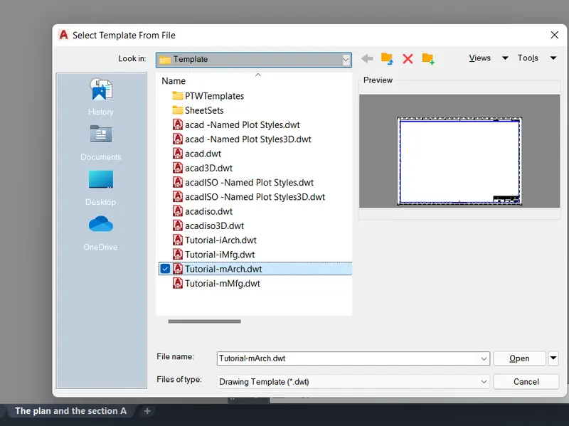
- The template should be inserted from the template folder by right clicking the layout tab and selecting Template<Tutorial-mArch.dwt.
- As per the given figure the viewport should be created inside the template with the "RECTANGLE command" and creating the two rectangles as @400,445 and @400,375 and selecting the first and second point of the viewport window inside the pagelayout.
- Make the created rectangle as a viewport by the MV command like Multiview<object and select the created rectangle to make the rectangle as a veiwport.
- The dimensions of the rectangular viewport will be denoted with the Dimlin or Dimlinear commandd and selecting the outerline of the rectangle viewport.
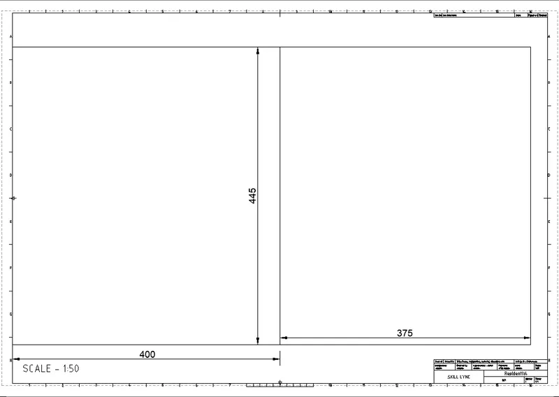
- Then evoke the Modelspace command by typing MS, it will take us to work inside the viewport which was created.
- There by adjusting the scale value 1:50 and the layout can be locked as per the given figure and the viewport window can be locked by MV command like Multiview<lock and select the required viewport to make the veiwport locked.
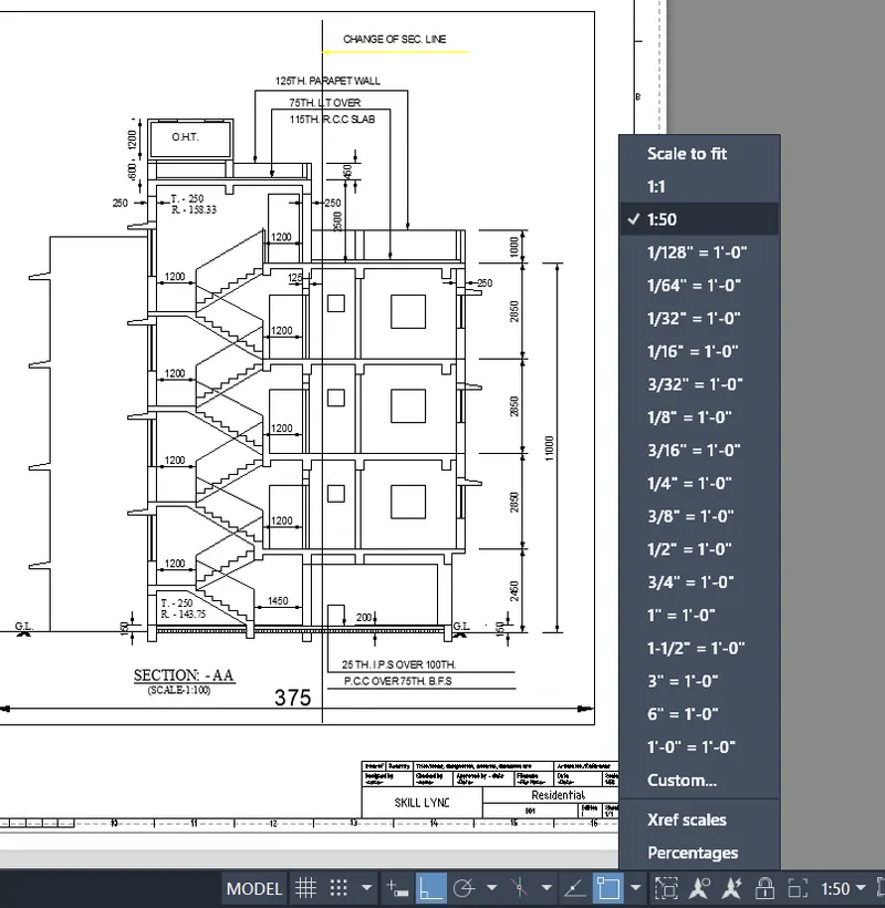
- The scale values can be denoted over the Pagelayout in Pagespace, with "Dtext" command.
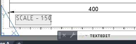
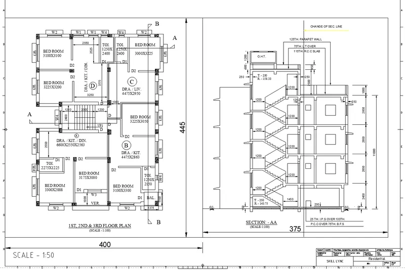
- Then the created layouts should be saved by Main menu<save as<.dwg and after saving it in a folder then it can be quick saved after every editing in the drawing with qsave command.
C ) RESULT:
- The layout of the plan and section A of the project in challenge 7, with the template Tutorial-mArch.dwt in a page layout as per the given Figure.
- The two rectangles as viewport @400,445 and @400,375 as per the shown figure dimensions.
- With the scale value of 1:50.
- In the A1 sized page layout.
2. ) LAYOUT OF THE KITCHEN DRAWN IN CHALLENGE 9 :
A ) AIM & INTRODUCTION:
AIM :
- To create the layout of the kitchen drawn in challenge 9, as per the given Figure.
- To create the viewport of the size as shown in Figure by using the MV command .
- To fit the model drawing inside the viewport with the required scale value.
- To create the A4 sized page layout and to plot it.
INTRODUCTION:
- It is to create the pagespace layout from the modelspace layout of the kitchen layout, which was either created or opened from the challenge 9.
- The viewport will be created in the pagespace layout as per the given figure.
- The layout of the plan and section A will be displayed in the four different viewport which was created in the pagelayout.
- The required scale value will be provided to fit the drawing within the viewport.
- Here, A4 pagesized layout is used to create the viewport and then it will be ploted.
B ) PROCEDURE:
- The layout of the kitchen has to be created or opened from the saved challenge 9 through a Main menu bar<Open<Challenge 9.
- Create the named view of the drawing which can be viewed in the viewport window if created, by selecting a name of the view from Title bar<View<Viewport manager and selecting plot as dwg to pdf and A4 paper size.
- The layout for the pagespace should be created from the Layout tab<Page setup manager.
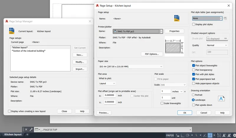
- As per the given figure the viewports should be created with the MV command" by selecting the first and second point of the viewport window inside the pagelayout.
- Make the created viewport into four layers by the MV command like Multiview<Layer< 4 and adjusting the four viewport windows sizes as per the given figure.
- Then evoke the Modelspace command by typing MS, it will take us to work inside the viewport which was created.
- There by adjusting the scale value 1:1 for above two viewport windows and scale value 1:2 for below two viewport windows.
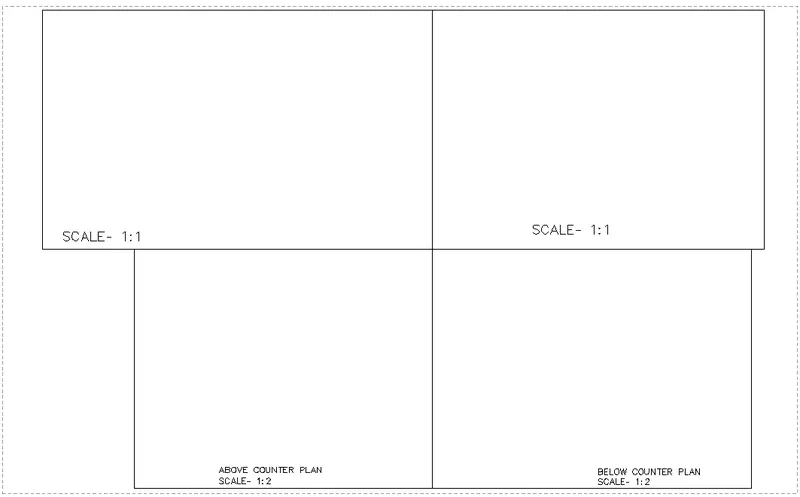
- The layout can be locked as per the given figure and the viewport window can be locked by MV command like Multiview<lock and select the required viewport to make the veiwport locked.
- The scale values can be denoted over the Pagelayout in Pagespace, with "Dtext" command.
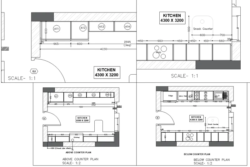
- Then the created layouts should be saved by Main menu<save as<.dwg and after saving it in a folder then it can be quick saved after every editing in the drawing with qsave command.
C ) RESULT:
- The layout of the kitchen drawn in challenge 9, as per the given Figure.
- The created viewport is divided into four layers by the MV command and adjusted the four viewport windows sizes as per the given figure..
- With the scale value 1:1 for above two viewport windows and scale value 1:2 for below two viewport windows
- In the A4 sized page layout.
3. ) LAYOUT OF THE SECTION CREATED IN CHALLENGE 9 :
A ) AIM & INTRODUCTION:
AIM :
- To create the layout of the section created in challenge 9, as per the given Figure.
- To create the two horizontal viewport as per the shown Figure by using the MV command .
- To fit the model drawing inside the viewport with the required scale value.
- To create the A4 sized page layout and to plot it.
INTRODUCTION:
- It is to create the pagespace layout from the modelspace layout of the section, which was either created or opened from the challenge 9.
- The viewport will be created in the pagespace layout as per the given figure.
- The layout of the section will be displayed in the two different horizontal viewport which was created in the pagelayout.
- The required scale value will be provided to fit the drawing within the viewport.
- Here, A4 pagesized layout is used to create the viewport and then it will be ploted.
B ) PROCEDURE:
- The layout of the drawing has to be created or opened from the saved challenge 9 through a Main menu bar<Open<Challenge 9.
- Create the named view of the drawing which can be viewed in the viewport window if created, by selecting a name of the view from Title bar<View<Viewport manager and selecting plot as dwg to pdf and A4 paper size.
- The layout for the pagespace should be created from the Layout tab<Page setup manager.
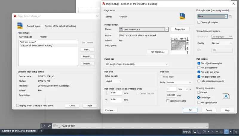
- As per the given figure the viewport should be created inside pagelayout by MV command and selecting the first and second point of the viewport window inside the pagelayout.
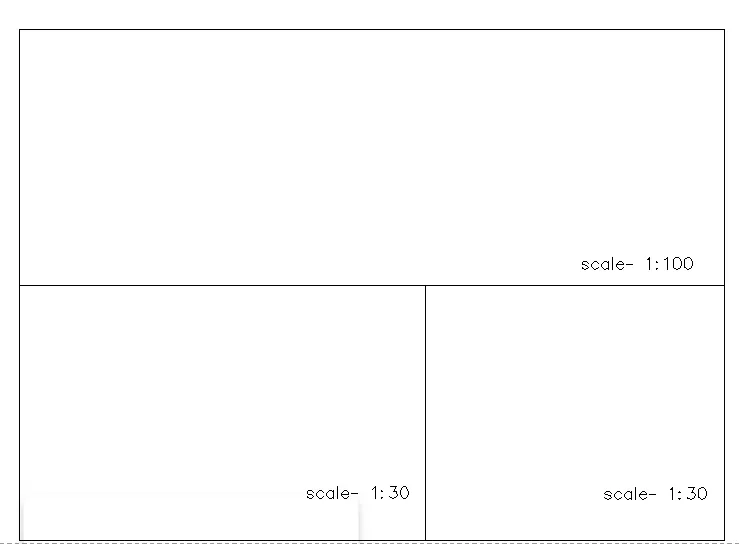
- Make the created viewport window into two different horizontal viewport by the MV command like Multiview<Layer<2<Horizontal .

- Then evoke the Modelspace command by typing MS, it will take us to work inside the viewport which was created.
- There by adjusting the scale value 1:100 for above viewport window and scale value 1:30 for below two viewport windows and the layout can be fit and locked as per the given figure and the viewport window can be locked by MV command like Multiview<lock and select the required viewport window to make the veiwport locked.
- The scale values can be denoted over the Pagelayout in Pagespace, with "Dtext" command.
- Then the created layouts should be saved by Main menu<save as<.dwg and after saving it in a folder then it can be quick saved after every editing in the drawing with qsave command.
C ) RESULT:
- The layout of the kitchen drawn in challenge 9, as per the given Figure.
- The created viewport is divided into two horizontal viewport by the MV command as per the given figure.
- With the scale value 1:100 for above viewport window and scale value 1:30 for below two viewport windows as per the given figure.
- In the A4 sized page layout.