Creation of Multiple viewports, Scaling the drawing and setting in Template in AutoCad
1)
AIM:
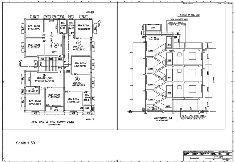
• To create a layout of the plan and section A of the project in challenge 7 using the template
• And use the MV command to create the viewport of the size from the given figure.
Introduction:
• Plan and Sections are different types of drawings used by architects to graphically represent a building design and construction.
• A plan drawing is a drawing on a horizontal plane showing a view from above.
• An Elevation drawing is drawn on a vertical plane showing a vertical depiction.
• A section drawing is also a vertical depiction but one that cuts through space showing what lies within.
Procedure:
• Click on AutoCAD application and open this application
• Open the drawing which is already drawn in challenge 9
• Take view command
• Click - New - Specify view - name-Plan
• Select ,Define window
• Select the window for plan and Enter
• Take view command> New,Specify view name > SectionAA
• Select > Define windowSelect the window for Section AA and Enter
• To create layout Right click on Layout 1
• Select > From Template
• Click > Tutorial-mArch
• Right click on new layout > Rename
• Rename > Plan-Elevation
• Open the Plan-Section layout
• Take rectangle command
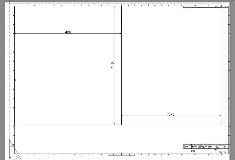
• Create the two rectangle as shown below
• One rectangle having dimension > 400, 445
• Other rectangle having dimension > 375, 445
• Take Ms command
• Take MV command
• Select > Object and Click the one rectangle and Enter and repeat for the another rectangle
• The two view ports are ready
• Type v in command bar
• One dialogue box will open
• Click > Plan > Set current > Ok
• Again do similar process for Section AA for other view port
• Select Scale > 1:50
• Select the two view ports
• Go to properties and Make it lock
• Take Ps command
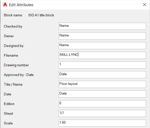
• Type > ATTEdit and Enter
• Select the object as template
• Edit the attribute as per requirement
• The attribute is ready as shown below
RESULT:
• Layout is created using template m.Arch.dwt.Viewport is created using MV command of size 400x445 and 375x445mm and the scale of viewport is set to 1:50.Attributes in the template are edited.A plot is taken using A1 size.
2)
AIM:
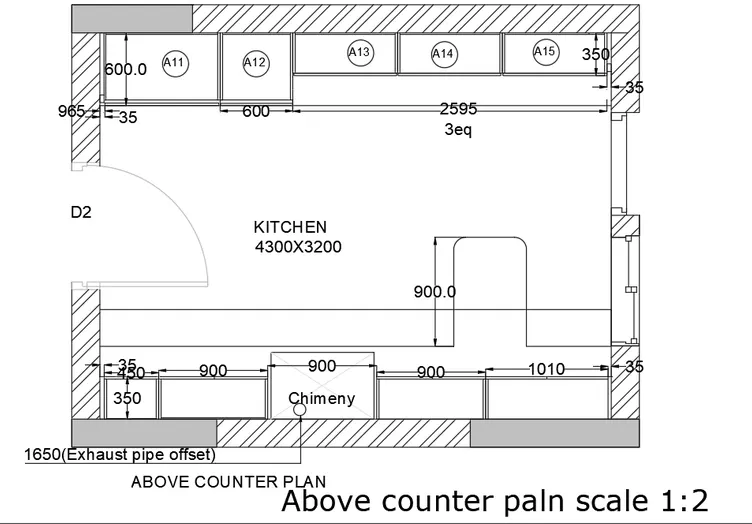
• To create the layout of the kitchen and providing hatches to it using the autocad in detail.
• Need to use the scale given in the figure and need to use the A4 size page for the layout.
INTRODUCTION:
• kitchen layout is the most important part of designing your perfect kitchen.
• It's the layout that will determine how you cook, how you eat and how you socialise.
• So whether you're totally remodelling the kitchen, buying new appliances or simply replacing the cabinets, we've included the top five most common kitchen layouts to help inspire you.
PROCEDURE:
• After drafting layout of kitchen click on layout option display which is present in left bottom or in view panel.
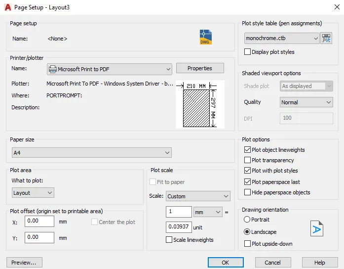
• right click on layout-select page setup manager to set the page for A4.
• select plot style as monochromatic.
• use ms-model space command to set the model.
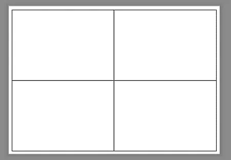
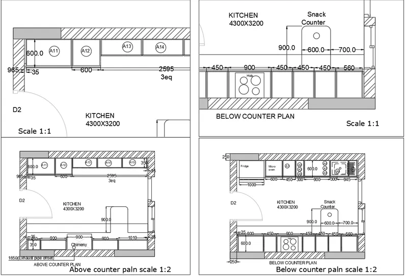
• divide the layout into 4 equal part using rectangle
• insert the view to be dispalyed into the rectangle.
• go to model area.
• go to view command, select view-enter the name.
• select window specify the view portion and enter.
• Similarly in model space click on third viewport.
• Enter the view above counter plan.
• Zoom and pan the viewport, so that the drawing fit in it Lock the viewport.
• Go to paper space and with command "T" enter the text as ABOVE COUNTER PLAN and SCALE 1:2.
• Similary in model space click on third viewport.
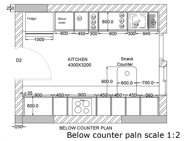
• Enter the view below counter plan.
• Zoom and pan the viewport, so that the drawing fit in it. Lock the viewport.
• Go to paper space and with command "T" enter the text as BELOW COUNTER PLAN and SCALE 1:2.
RESULT:
• Different view of kitchen for layout in model space is createdlayout with four viewports, with A4 sheet is created, a plot is created.
3)
AIM:
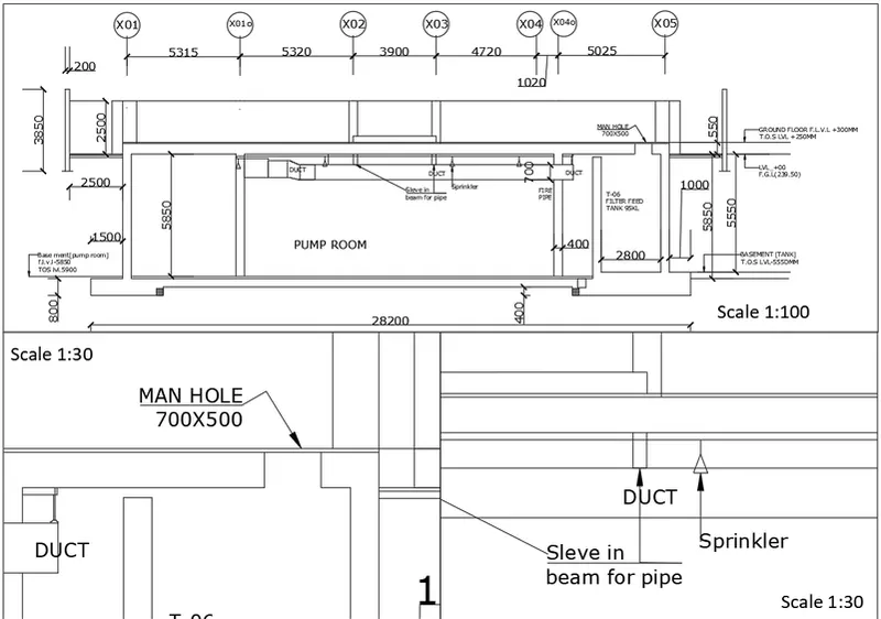
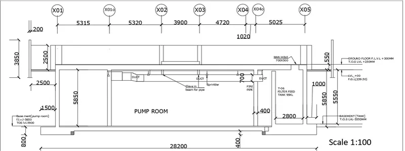
To create the section view of an industrial building.
And need to provide appropriate hatches and fimensions where ever required.
INTRODUCTION:
• In reference to architectural drawing, the term section typically describes a cut through the body of a building, perpendicular to the horizon line.
• A section drawing is one that shows a vertical cut transecting, typically along a primary axis, an object or building.
• A section diagram is a view of the building that slices through the building to better see the specific aspects of the building better.
• This drawing is particularly interesting because it cuts through and goes underground (to the new parking area) as well.
Procedure :
• Click on AutoCAD application and open this application
• Open the drawing which is already drawn in challenge 9
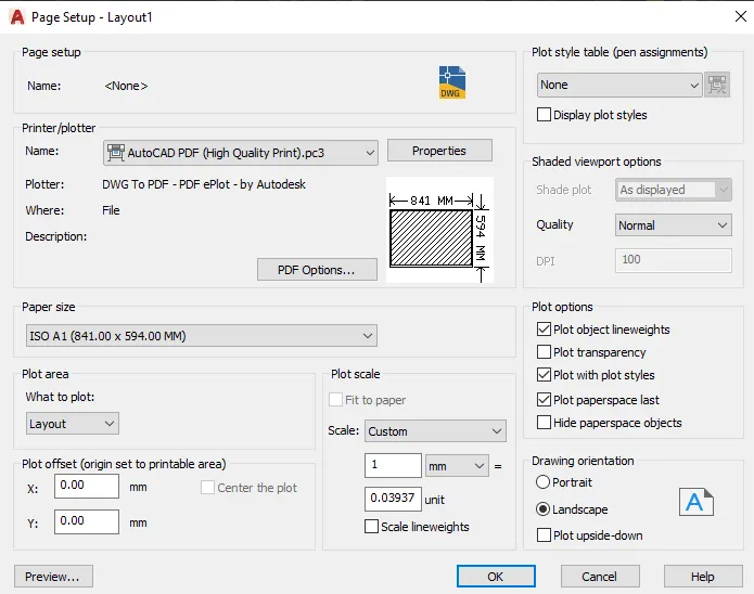
• Take page setup command
• Click > New
• Page setup Name > Industrial building layout
• Set the settings as per shown below and Enter
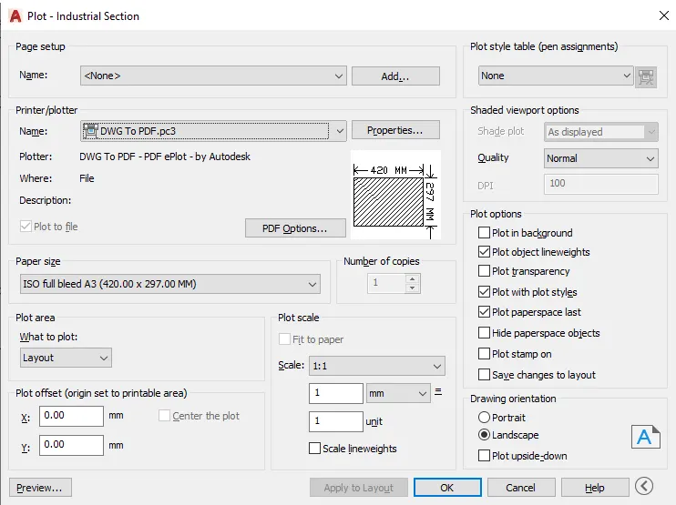
• Click > Set current and Enter
• Take view command
• Click > New
• Specify view name > Section View
• Select > Define window
• Select the window for view and Enter
• Similarly do the same procedure to create other views
• To create layout ,Right click on Layout1,Right click on new layout > Rename > Industrial Building
• Open the Industrial Building layout
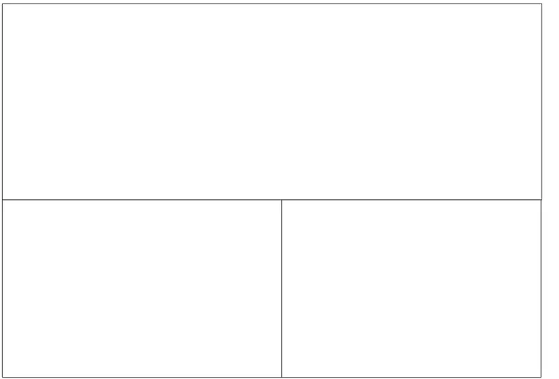
• Type > MV > enter
• Specify> 3
• Select the corner as it will gives following results
• Take Ms command
• Take MV command
• Select > Object
• Click the one rectangle and Enter
• Similarly do for the another rectangle
• The two view ports are ready
• Type v in command bar
• One dialogue box will open
• Click > Kitchen-Above counter Plan > Set current> Ok
• Again do similar process for other view port
• Select Scale > as per view ports shown in drawing
• Select the all view ports
• Go to properties
• Make it lock
• Type plot in command bar
• Dialogue box will open
• The setting is done as per below
RESULT:
• Layout of the section of industrial building is created, viewport is created by MV command and scale 1:30 and 1:100 is given.
• Plot of the layout is taken.