Creating a Floor plan, Footing detail and Isometric view using AutoCad
1)
Aim:
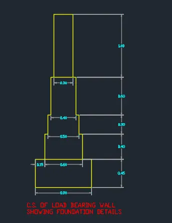
To draw c.s of load bearing wall showing foundation details
PROCEDURE :
• In the command prompt type QNEW
• click on imperical template <advaced setup < decimal
In the command prompt type units
set the units
• In the command prompt type REC
specify first corner point 1,1
In command prompt click dimensions
specify length of the rectangle 0.90
specify width of the rectangle 0.45
• In the command prompt type REC
specify first corner point 1.15,1.45
In command prompt click dimensions
specify length of the rectangle 0.60
specify width of the rectangle 0.40
• In the command prompt type REC
specify first corner point 1.20,1.85
In command prompt click dimensions
specify length of the rectangle 0.50
specify width of the rectangle 0.30
• In the command prompt type REC
specify first corner point 1.25, 2.15
In command prompt click dimensions
specify length of the rectangle 0.40
specify width of the rectangle 0.60
• In the command prompt type REC
specify first corner point 1.30, 2.75
In command prompt click dimensions
specify length of the rectangle 0.30
specify width of the rectangle 1.00
OUTPUT:
c.s of load bearing wall showing foundation details
2)
AIM:
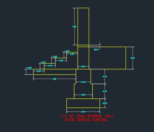
To draw C.S of load bearing wall over spread footing using AutoCAD Software
PROCEDURE:
• In the command prompt type QNEW
• click on imperical template , advaced setup , decimal
In the command prompt type units
set the units
• In the command prompt type REC
specify first corner point 1,1
In command prompt click dimensions
specify length of the rectangle 0.90
specify width of the rectangle 0.25
• In the command prompt type REC
specify first corner point 1.2 , 1.25
In command prompt click dimensions
specify length of the rectangle 0.50
specify width of the rectangle 0.40
• In the command prompt type REC
specify first corner point 1.25 , 1.65
In command prompt click dimensions
specify length of the rectangle 0.40
specify width of the rectangle 0.40
• In the command prompt type REC
specify first corner point 1.30 , 2.05
In command prompt click dimensions
specify length of the rectangle 0.30
specify width of the rectangle 0.60
• In the command prompt type REC
specify first corner point 1.30 , 2.65
In command prompt click dimensions
specify length of the rectangle 0.30
specify width of the rectangle 0.05
• In the command prompt type REC
specify first corner point 1.30 , 2.7
In command prompt click dimensions
specify length of the rectangle 0.30
specify width of the rectangle 1.0
• In the command prompt type REC
specify first corner point 1.25,2.05
In command prompt click dimensions
specify length of the rectangle 1.15
specify width of the rectangle 0.15
In the command prompt type line
specify starting point 0.40 ,2.05
• In the command prompt type @0.15<90
• In the command prompt type @ 0.3<0
• In the command prompt type @ 0.15<90
• In the command prompt type @ 0.3<0
• In the command prompt type @0.15<90
• In the command prompt type @ 0.3<0
OUTPUT:
CS of load bearing wall over spread footing
3)
AIM:
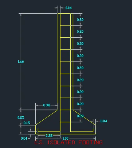
To draw C.S Isolated footing using AutoCAD Software
PROCEDURE :
• In the command prompt type ONEW
• click on imperical template , advaced setup , decimal
In the command prompt type units
set the units
• In the command prompt type line
• In the command promt specify start point 1,1
• In the command prompt type @1<0
• In the command prompt type @0.15<90
In the command prompt type line
• In the command prompt type 1.04 ,1.04
• In the command prompt type @0.38<0
• In the command prompt type @1.96<90
• In the command prompt type @0.17<0
• In the command prompt type @1.96<270
• In the command prompt type @0.38<0
• In the command prompt type @0.05<90
In the command prompt type line
• In the command prompt type 1.04 ,1.04
• In the command prompt type @0.05<90
In the command prompt type line
• In the command prompt specify start point 1.42,3.00
• In the command prompt type @0.04<180
• In the command prompt type @1.60<270
• join coordinate points ( 1.38 ,1.40 ) and (1, 1.15 ) using line command
• In the command promtp specify start point 1.59,3.00
• In the command prompt type @0.04<180
• In the command prompt type @1.60<270
• join coordinate points ( 1.63 ,1.40 ) and (2 ,1.15 ) using line command
• click on the line in which coordinate points are (1.42 ,3.00 ) and ( 1.59 ,3.00 )
In the command promt type offset
• In the command prompt type distance 0.20
• In the command prompt click multiple ( click on the objects till you get the number of desired segments )
OUTPUT :
4)
AIM:
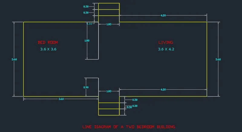
To draw a line diagram of a two bedroom building
PROCEDURE:
• In the command prompt type QNEW
• click on imperical template , advaced setup , decimal
In the command prompt type units
Type: decimal, precision = 0.00 , angle = decimal degree
• In the command prompt type line
• In the command prompt specify start point 1,1
• In the command prompt [email protected]<0
• In the command prompt type @0.90<270
• In the command prompt type @1<0
• In the command prompt type @0.90<90
• In the command prompt type @4.2<0
• In the command prompt type @0.9,90
• In the command prompt type @3.6@180
• In the command prompt type @0.90<90
• In the command prompt type @1<180
• In the command prompt type @0.90<270
• In the command prompt type @3.60<180
In the command prompt click close
• In the command prompt type line
• In the command prompt specify start point 4.60 ,1
• In the command prompt type @0.90<90
• In the command prompt type line
• In the command prompt specify start point 4.60 ,4.60
• In the command prompt type @1.8<270
• In the command prompt type offset
• In the command prompt type 0.30
• click on the line in which coordinate points are (4.60, 0.10) and (5.60,0.10 )
click on the previous line to get segments
• click on the line in which coordinate points are ( 4.60 , 5.50) and (5.60 ,5.50 )
click on the previous line to get segements
OUTPUT :
line diagram of a two bedroom building
5)
AIM:
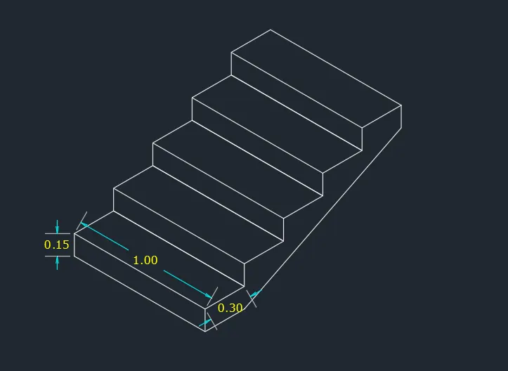
To draw isometric view of the steps
PROCEDURE:
Type DS in the connmand line and press enter.
unpick snap on and grid on options
Tick on isometric snap in snap type.
This will activates the isometric screen.
Type PL in the command line and press Enter.
Specify the start point a.
Take isoplane left
Specify the next pointl .curser towards NW
Take isoplane right
Specify the next point.15. curser towards N
Specify the next point'. curser towards SE
Specify the next point 15. curser towards E
Type PL in the command line and press Enter.
Specify the start point b.
Take isoplane top
Specify the next point.30. curser towards NE
Specify the next point'. curser towards NW
Specify the next point.30. curser towards SW
Type CO in the command line and press enter.
Select the complete step and press enter
Select b as the base point and place it 4 times at the
positions c, d, e and f
Type L in the command line and press Enter.
Specify the start point: g
Take isoplane right
Specify the next point:0.15, curser towards S
Type L in the command line and press Enter.
Specify the start point: h
Take isoplane right
Specify the next point'.30, curser towards NE
Type L in the command line and press Enter.
Specify the start point: i
Specify the start point: j
OUTPUT:
6)
AIM:
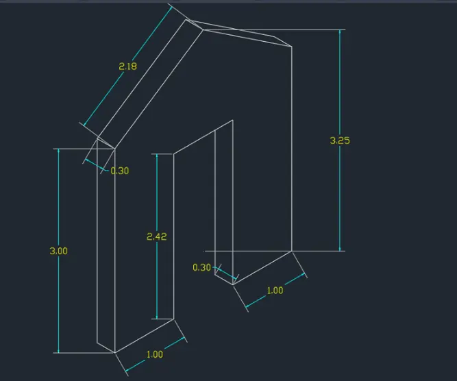
To draw an isometric view of gabble wall
PROCEDURE:
Type DS in the connmand line and press enter.
unpick snap on and grid on options
Tick on isometric snap in snap type.
This will activates the isometric screen.
Type L in the command line and press Enter.
Specify the start point a.
Take isoplane left
Specify the next point.30 .curser towards NW
Specify the next point3. curser towards N
Specify the next point.30. curser towards SE
Specify the next points. curser towards E
Type L in the command line and press Enter.
Specify the start point a.
Take isoplane top
Specify the next pointl .curser towards NE
Specify the next pointl .curser towards NE
Specify the next pointl .curser towards NE