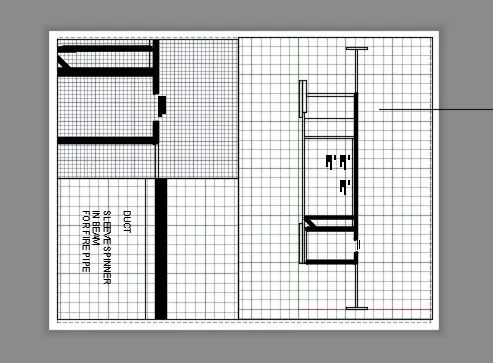
Creation of Multiple viewports, Scaling the drawing and setting in Template in AutoCad
1. Aim: Create a layout of the Plan and Section A of the project in Challenges 7, using the template Tutorial-mArch.dwt in a scale as given in the Figure. To draw a given floor plan using autocad.
procedure: The following steps should be followed as a procedure to draw a given floor plan using autocad
- To draw the given floor plan in autocad, the following steps should be followed as a procedure. At first open the AutoCAD and set dimensions that the dimensions are in mm.
- Then enter the Line command in AutoCAD and after that enter the first point of the given diagram as that line should be started at the point in the coordinate system.
- Then with that point draw a rectangle using rectangle command using the dimensions of the rectangle as length is 3100 and width is 3100.
- by using the offset command in autocad make offsset of 230 for the outer wall ie enter the dimension of the offset as 230.
- then select the last line of the rectangle and make offset of 2550 ie the width of the both bedrooms by using the offset command in autocad.
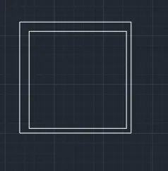
- next make offset of that line 150 ie the width of the inner wall is equal to 150, ie enter the offset command and give the width of 150.
- next make the offset of the line left corner of the rectangle to get the length of the bedrooms by using the offset command in autocad give the offset lenth as 150.
- next make offset of that line 150 ie the width of the inner wall is equal to 150, ie enter the offset command and give the width of 150.
- next make the offset of the line left corner of the rectangle to get the length of the bedrooms by using the offset command in autocad give the offset lenth as 150.
- Then with that point draw a rectangle using rectangle command using the dimensions of the rectangle as length is 3000 and width is 3225.
- by using the offset command in autocad make offsset of 230 for the outer wall ie enter the dimension of the offset as 230.
- then select the last line of the rectangle and make offset of 3830 ie the width of the both bedrooms by using the offset command in autocad.
- next make the offset of the line left corner of the rectangle to get the length of the bedrooms by using the offset command in autocad give the offset lenth as 1250.
- next make offset of that line 1250 ie the width of the inner wall is equal to 150, ie enter the offset command and give the width of 1250.
- next make the offset of the line left corner of the rectangle to get the length of the bedrooms by using the offset command in autocad give the offset lenth as 150.
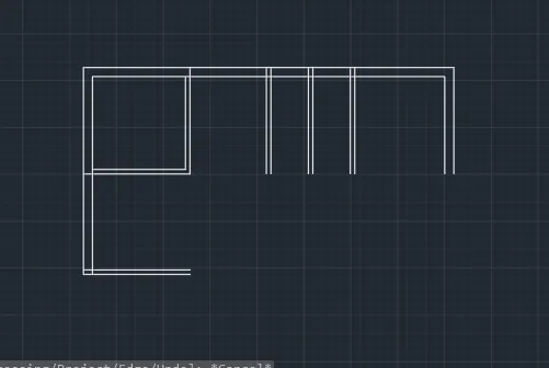
- next make offset of that line 150 ie the width of the inner wall is equal to 150, ie enter the offset command and give the width of 150.
- next make the offset of the line left corner of the rectangle to get the length of the bedrooms by using the offset command in autocad give the offset lenth as 4475.
- next make offset of that line 2950 ie the width of the inner wall is equal to 3200, ie enter the offset command and give the width of 150.
- extend the line using the command extend that entre E double enter and select the line which has to be extended.
- connect the lines using the line command and close the entire walls of outer cross section by drawing the lines using the lines command.
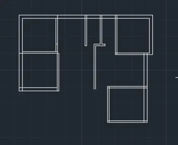
- next make offset of that line 3225 ie the width of the inner wall is equal to 3050, ie enter the offset command and give the width of 150.
- by using the offset command in autocad make offsset of 9" for the outer wall ie enter the dimension of the offset as 300.
- make the offet of 2150 and from that line make offset of 2400 to get the width of the living room and the kitchen and make offset from that line of 150 for the inner wall and 300 as the outer wall as diameter.
- Trim the unwanted lines for the door and the other openings the length of the line of that doors as per the given dimensions.
- for stair case make the offset of the line left corner of the rectangle to get the length of the staircase 300 and raiser 150 by using the offset command in autocad give the offset lenth as 150.
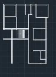
- next make the offset of the line to get the length of the toilets by using the offset command in autocad give the offset lenth as 150 in both sides.
- next make the offset of the line left corner of the rectangle to get the length of the one of the bathrooms by using the offset command in autocad give the offset lenth as 6600.
- next make the offset of the line right corner of the rectangle to get the length of the another bathroom by using the offset command in autocad give the offset lenth as 2550.
- next make offset of that line 150 ie the width of the inner wall is equal to 300 ie enter the offset command and give the width of 150
- delete the unwanted lines by using the trim command in autocad.
- next make the offset of the line right corner of the rectangle to get the length of the another bathroom by using the offset command in autocad give the offset lenth as 4475.
- next make offset of that line 1500 ie the width of the inner walls of lift is equal to 1600, ie enter the offset command and give the width of 150
- by using the offset command in autocad make offsset of 300 for the outer wall ie enter the dimension of the offset as 300.
- make the offet of 3175 and from that line make offset of 3000 to get the width of the living room and the another room and make offset from that line of 150 for the inner wall and 300 as the outer wall as diameter.
- Trim the unwanted lines for the door and the other openings the length of the line of that doors as per the given dimensions.
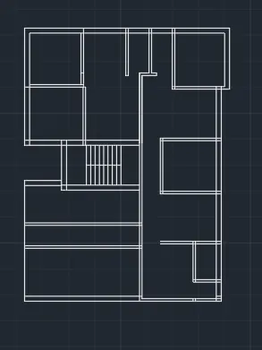
- next make offset of that line 3300 ie the width of the inner wall is equal to 2888, ie enter the offset command and give the width of 150.
- by using the offset command in autocad make offsset of 9" for the outer wall ie enter the dimension of the offset as 300.
- make the offet of 2275 and from that line make offset of 1225 to get the width of the living room and the balcony and make offset from that line of 150 for the inner wall and 300 as the outer wall as diameter.
- Trim the unwanted lines for the door and the other openings the length of the line of that doors as per the given dimensions.
- for stair case make the offset of the line left corner of the rectangle to get the length of the staircase 300 and raiser 150 by using the offset command in autocad give the offset lenth as 150.
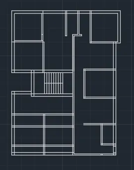
- copy the line of the inner rectangle as per the measurement taken by the size of the windows and the door openings.
- Trim the unwanted lines for the door and the other openings the length of the line of that doors as per the given dimensions.
- copy all the windows and another set of windows and place it on the required places where the windows sechdule are given and then copy and place it on the required window placing secdule as per the measurement
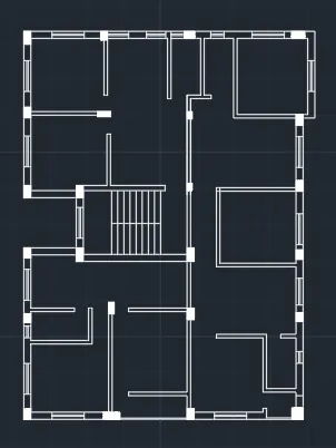
- and by using the multitext command or by copying the text which has been present in the another column the header text has been written sizes of the rooms or edited and edit the text as per the required and paste it on the row which has been present and edit the text and place the texting height as per the required table as shown in the figure below.
- edit the text as per the required and paste it on the row which has been present and edit the text and place the texting height as per the required table as shown in the figure below.
- to draw the door by using the autocad commands that by line command we can draw the line and by arc command we can draw the arc and by rectangle command we can draw the chouckets and then trim the unwanted lines. repeat the process for each and every door point side as per the required floor plan.
- enter the dimensions of the rooms as per the given dimensions using the Multi text command in autocad and enter the dimensions wich is required in the given floor plan to gte the required floor plan of the bathrooms and vanity and all other rooms.
- and by using the multitext command or by copying the text which has been present in the another column the header text has been written sizes of the rooms or edited and edit the text as per the required and paste it on the row which has been present and edit the text and place the texting height as per the required table as shown in the figure below.
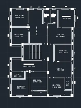
- To make the table as a single block then select the block option and create the block to create the block select on create block on view option and then for creating a block we have to pick the point ie the reference point and then select the lines or the objects which has to make block and then if we want to make annotative make annottive and then press ok.
- here to create block click on create block option and create the block name in the block name option then pick up the reference point and then slect the texts and lines which have to make block and then press ok to crate the block.
- Now, you need to tell AutoCAD what the insertion point should be. In other words, when you place the block, the point about which the block appears at your cursor Click the Select Objects button and select the objects you want to be stored in the block.
- To make the table as a single block then select the block option and create the block to create the block select on create block on view option and then for creating a block we have to pick the point ie the reference point and then select the lines or the objects which has to make block and then if we want to make annotative make annottive and then press ok.
- here to create block click on create block option and create the block name in the block name option then pick up the reference point and then slect the texts and lines which have to make block and then press ok to crate the block.
Aim: Create a layout of the Plan and Section A of the project in Challenges 7, using the template Tutorial-mArch.dwt in a scale as given in the Figure. To draw a given floor plan using autocad.To draw a given floor plan cross section view using autocad.
procedure: The following steps should be followed as a procedure to draw a given floor plan cross section view using autocad
- To draw the given floor plan cross section view in autocad, the following steps should be followed as a procedure. At first open the AutoCAD and set dimensions that the dimensions are in mm.
- Then enter the Line command in AutoCAD and after that enter the first point of the given diagram as that line should be started at the point in the coordinate system.
- Then with that point draw a rectangle using rectangle command using the dimensions of the rectangle as length is 2850 and width is 2850.
- by using the offset command in autocad make offsset of 230 for the outer wall ie enter the dimension of the offset as 230.
- then select the last line of the rectangle and make offset of 2550 ie the width of the both bedrooms by using the offset command in autocad.
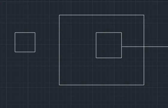
- next make offset of that line as per the measuement taken ie the width of the inner lines is equal per the measuement taken, ie enter the offset command and give the width ans in the line seetings select the required line type to change the line type .
- next make the offset of the line left corner of the rectangle to get the length of the inner spaces of the wardrobe by using the offset command in autocad give the offset lenth as per the measuement taken delete the unwanted lines by using the trim command in autocad in the line seetings select the required line type to change the line type.
- next make the offset of the line left corner of the rectangle to get the length of the one of the liner lines of the column by using the offset command in autocad give the offset lenth as per the measuement taken in the line seetings select the required line type to change the line type.
- next make the offset of the line right corner of the rectangle to get the length of the another in the line seetings select the required line type to change the line type by using the offset command in autocad give the offset lenth as 1200 in the line seetings select the required line type to change the line type.
- next make offset of that line per the measuement taken ie the width of the inner wall is equal to ie enter the offset command and give the width of in the line seetings select the required line type to change the line type
- delete the unwanted lines by using the trim command in autocad in the line seetings select the required line type to change the line type.
- next make the offset of the line right corner of the rectangle to get the length of the another in the line seetings select the required line type to change the line type by using the offset command in autocad give the offset lenth as in the line seetings select the required line type to change the line type.
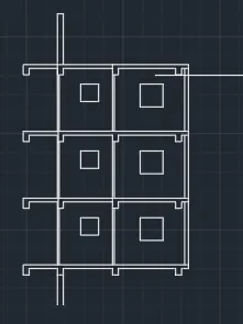
- next make the offset of the line left corner of the rectangle to get the length of the one of the liner lines of the column by using the offset command in autocad give the offset lenth as per the measurement taken in the line seetings select the required line type to change the line type.
- next make the offset of the line right corner of the rectangle to get the length of the another in the line seetings select the required line type to change the line type by using the offset command in autocad give the offset lenth as per the measurement taken in the line seetings select the required line type to change the line type.
- next make offset of that line ie the width of the inner wall is equal to per the measurement taken ie enter the offset command and give the width of in the line seetings select the required line type to change the line type
- place the columns as per the required places and then make that copy all the columns and rotate as per the required schdule column cross section placing.
- delete the unwanted lines by using the trim command in autocad in the line seetings select the required line type to change the line type.
- next make the offset of the line right corner of the rectangle to get the length of the another in the line seetings select the required line type to change the line type by using the offset command in autocad give the offset lenth as in the line seetings select the required line type to change the line type.
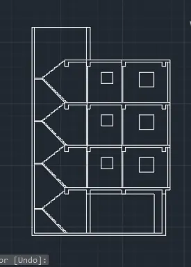
- next make offset of that line as per the diagram ie the width of the inner lines is equal to some dimensions, ie enter the offset command and give the width of ans in the line seetings select the required line type to change the line type .
- next make the offset of the line left corner of the rectangle to get the length of the inner spaces of the wardrobe by using the offset command in autocad give the offset lenth as delete the unwanted lines by using the trim command in autocad in the line seetings select the required line type to change the line type.
- next make the offset of the line left corner of the rectangle to get the length of the one of the liner lines of the column by using the offset command in autocad give the offset lenth as in the line seetings select the required line type to change the line type.
- next make the offset of the line right corner of the rectangle to get the length of the another in the line seetings select the required line type to change the line type by using the offset command in autocad give the offset lenth as in the line seetings select the required line type to change the line type.
- next make offset of that line ie the width of the inner wall is equal to 150 ie enter the offset command and give the width of as per the diagram taken in the line seetings select the required line type to change the line type.
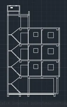
- and by using the multitext command or by copying the text which has been present in the another column the header text has been written sizes of the rooms or edited and edit the text as per the required and paste it on the row which has been present and edit the text and place the texting height as per the required table as shown in the figure below.
- edit the text as per the required and paste it on the row which has been present and edit the text and place the texting height as per the required table as shown in the figure below.
- to draw the door by using the autocad commands that by line command we can draw the line and by arc command we can draw the arc and by rectangle command we can draw the chouckets and then trim the unwanted lines. repeat the process for each and every door point side as per the required floor plan.
- enter the dimensions of the rooms as per the given dimensions using the Multi text command in autocad and enter the dimensions wich is required in the given floor plan to gte the required floor plan of the bathrooms and vanity and all other rooms.
- and by using the multitext command or by copying the text which has been present in the another column the header text has been written sizes of the rooms or edited and edit the text as per the required and paste it on the row which has been present and edit the text and place the texting height as per the required table as shown in the figure below.
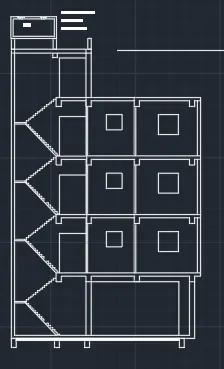
- To make the table as a single block then select the block option and create the block to create the block select on create block on view option and then for creating a block we have to pick the point ie the reference point and then select the lines or the objects which has to make block and then if we want to make annotative make annottive and then press ok.
- here to create block click on create block option and create the block name in the block name option then pick up the reference point and then slect the texts and lines which have to make block and then press ok to crate the block.
- Now, you need to tell AutoCAD what the insertion point should be. In other words, when you place the block, the point about which the block appears at your cursor Click the Select Objects button and select the objects you want to be stored in the block.
- To make the table as a single block then select the block option and create the block to create the block select on create block on view option and then for creating a block we have to pick the point ie the reference point and then select the lines or the objects which has to make block and then if we want to make annotative make annottive and then press ok.
- here to create block click on create block option and create the block name in the block name option then pick up the reference point and then slect the texts and lines which have to make block and then press ok to crate the block.
- Now, you need to tell AutoCAD what the insertion point should be. In other words, when you place the block, the point about which the block appears at your cursor Click the Select Objects button and select the objects you want to be stored in the block.
- Open the drawing of plan and section which is already drawn in the challenge no 7.
- In the left corner of the auto cad there is the tab named model. In the right side of the model tab there is a tab named layout
- Left click on the layout and create new layout from the option FROM TEMPLATE.. and select M arch template select ISO A1 layout.
- Then open the new layout created.
- Rename the layout as plan and section.
- Now enter command page setup manager.
- A new window of page setup will be opened. Modify the layout.
- Select printer as DWG to PDF.
- Elect paper size as A1. And click OK.
- Now enter the command as MS in the command box and draw rectangles of 440 X 445 and another of 375 X 445.
- Now enter the command MV and select both the rectangles. Set the scale as 1:50 for the drawing.
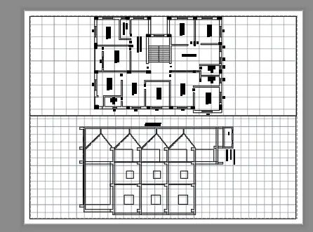
2. Aim: Create a layout of the Kitchen drawn in Challenge 9 as shown in Figure. Use the scale as shown in the Figure. Use A4 Size page for the layout. To draw a given cross section of kitchen using autocad.
procedure: The following steps should be followed as a procedure to draw a given cross section of a kitchen using autocad
- To draw the given cross section of a kitchen in autocad, the following steps should be followed as a procedure. At first open the AutoCAD and set dimensions that the dimensions are in mm.
- Then enter the Line command in AutoCAD and after that enter the first point of the given diagram as that line should be started at the point in the coordinate system.
- Draw a rectangle using the autocad command enter the dimensions as per the given requirement as per the table.
- Then with that point draw a rectangle using rectangle command using the dimensions of the rectangle as length is 4300 and width is 2300
- by using the offset command in autocad make offsset of 480 for the outer wall ie enter the dimension of the offset as 480.
- then select the last line of the rectangle and make offset of 12 ie the width of the both sides of the cross section of a wardrobe by using the offset command in autocad.
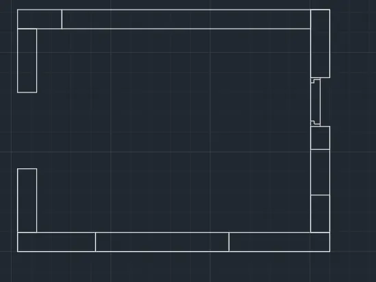
- next make offset of that line 600 ie the width of the inner lines is equal to 450, ie enter the offset command and give the width of 300.
- next make the offset of the line left corner of the rectangle to get the length of the inner spaces of the wardrobe by using the offset command in autocad give the offset lenth as 300 delete the unwanted lines by using the trim command in autocad.
- next make the offset of the line left corner of the rectangle to get the length of the one of the bathrooms by using the offset command in autocad give the offset lenth as 450.
- next make the offset of the line right corner of the rectangle to get the length of the another bathroom by using the offset command in autocad give the offset lenth as 900.
- next make offset of that line 450 ie the width of the inner wall is equal to 300 ie enter the offset command and give the width of 450
- delete the unwanted lines by using the trim command in autocad.
- next make the offset of the line right corner of the rectangle to get the length of the another bathroom by using the offset command in autocad give the offset lenth as 945.
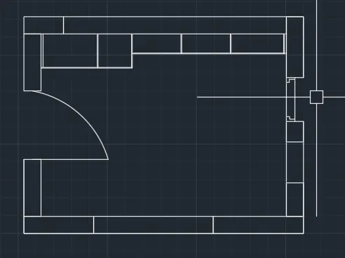
- to draw the door by using the autocad commands that by line command we can draw the line and by arc command we can draw the arc and by rectangle command we can draw the chouckets and then trim the unwanted lines. repeat the process for each and every door point side as per the required floor plan.
- enter the dimensions of the rooms as per the given dimensions using the Multi text command in autocad and enter the dimensions wich is required in the given floor plan to gte the required floor plan of the bathrooms and vanity and all other rooms.
- next make offset of that line 600 ie the width of the inner lines is equal to 450, ie enter the offset command and give the width of 300.
- next make the offset of the line left corner of the rectangle to get the length of the inner spaces of the wardrobe by using the offset command in autocad give the offset lenth as 300 delete the unwanted lines by using the trim command in autocad.
- next make the offset of the line left corner of the rectangle to get the length of the one of the bathrooms by using the offset command in autocad give the offset lenth as 450.
- next make the offset of the line right corner of the rectangle to get the length of the another bathroom by using the offset command in autocad give the offset lenth as 900.
- next make offset of that line 450 ie the width of the inner wall is equal to 300 ie enter the offset command and give the width of 450
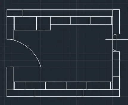
- give the dimensions of that usimg the dimensions settings in autocad and then make the settings in the annatation as shown in the figure below.
- and by using the multitext command or by copying the text which has been present in the another column the header text has been written size or edited and edit the text as per the required and paste it on the row which has been present and edit the text and place the texting height as per the required table as shown in the figure below.
- edit the text as per the required and paste it on the row which has been present and edit the text and place the texting height as per the required table as shown in the figure below.
- to draw the door by using the autocad commands that by line command we can draw the line and by arc command we can draw the arc and by rectangle command we can draw the chouckets and then trim the unwanted lines. repeat the process for each and every door point side as per the required kitchen cross section.
- enter the dimensions of the kitchen cross section as per the given dimensions using the Multi text command in autocad and enter the dimensions wich is required in the given floor plan to gte the required floor plan of the bathrooms and vanity and all other rooms.
- and by using the multitext command or by copying the text which has been present in the another column the header text has been written sizes of the rooms or edited and edit the text as per the required and paste it on the row which has been present and edit the text and place the texting height as per the required table as shown in the figure below.
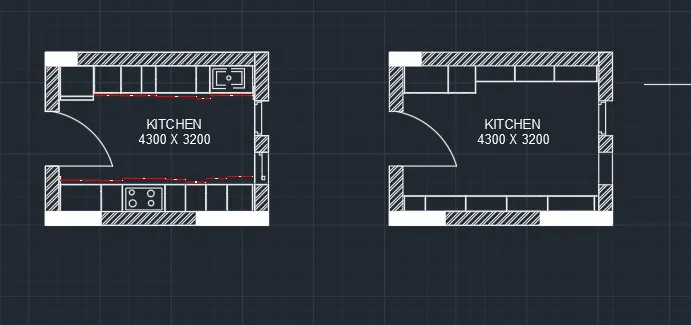
- To make the table as a single block then select the block option and create the block to create the block select on create block on view option and then for creating a block we have to pick the point ie the reference point and then select the lines or the objects which has to make block and then if we want to make annotative make annottive and then press ok.
- here to create block click on create block option and create the block name in the block name option then pick up the reference point and then slect the texts and lines which have to make block and then press ok to crate the block.
- Now, you need to tell AutoCAD what the insertion point should be. In other words, when you place the block, the point about which the block appears at your cursor Click the Select Objects button and select the objects you want to be stored in the block.
- To make the table as a single block then select the block option and create the block to create the block select on create block on view option and then for creating a block we have to pick the point ie the reference point and then select the lines or the objects which has to make block and then if we want to make annotative make annottive and then press ok.
- here to create block click on create block option and create the block name in the block name option then pick up the reference point and then slect the texts and lines which have to make block and then press ok to crate the block.
- Open the drawing of Kitchen which is already drawn in the challenge 9.
- In the left corner of the auto cad there is the tab named model. In the right side of the model tab there is a tab named layout.
- Left click on the layout and create new layout.
- Then open the new layout created.
- Rename the layout as kitchen layout.
- Now enter command page setup manager.
- A new window of page setup will be opened.
- Modify the layout.
- Select printer as DWG to PDF.
- Elect paper size as A4. And click OK.
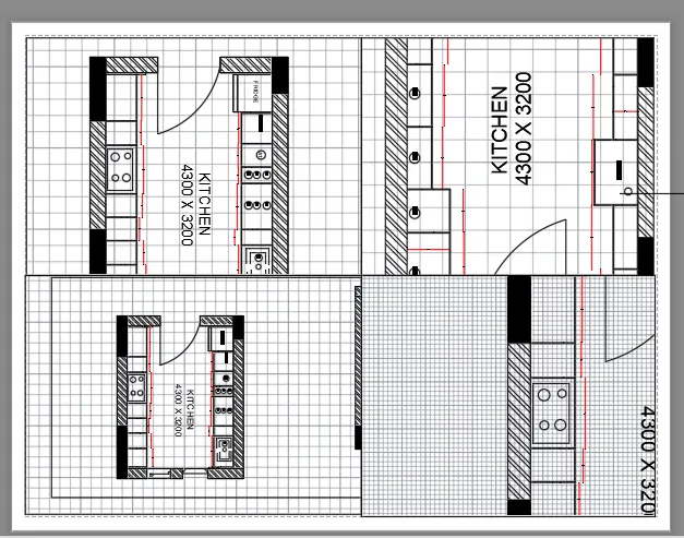
- Enter the command as VIEWPORTS.
- A window of view ports will be appearing on the screen. Select the viewport type as four equal and enter ok.
- Then specify the first corner point at the left top of the page and drag to another corner point in the right bottom of the page. Using the MS command zoom the views as desired of below and above counter plan
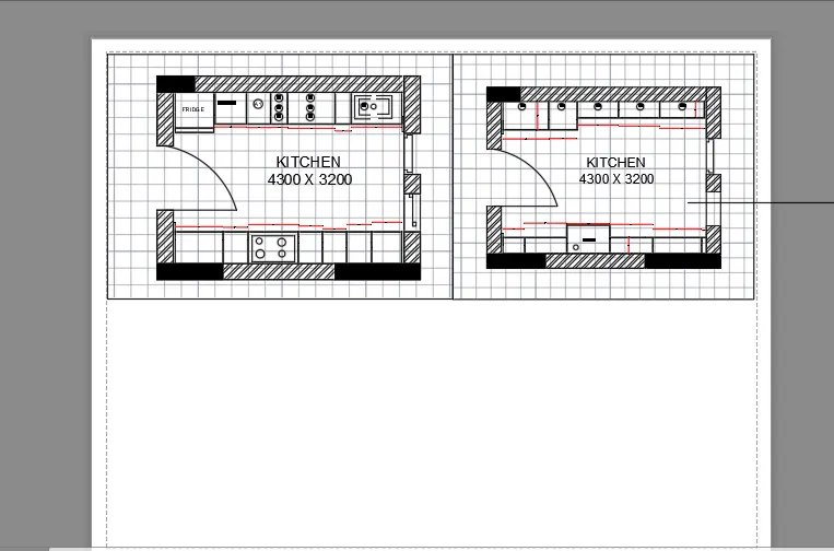
- In the left corner of the auto cad there is the tab named model. In the right side of the model tab there is a tab named layout.
- Left click on the layout and create new layout.
- Then open the new layout created.
- Rename the layout as kitchen layout.
- Now enter command page setup manager.
- A new window of page setup will be opened.
- Modify the layout.
- Select printer as DWG to PDF.
- Elect paper size as A4. And click OK.
- Enter the command as VIEWPORTS.
- A window of view ports will be appearing on the screen. Select the viewport type as four equal and enter ok.
- Then specify the first corner point at the left top of the page and drag to another corner point in the right bottom of the page. Using the MS command zoom the views as desired of below and above counter plan
3. Aim: Create a layout of the section created in Challenges 9. Use scale as mentioned in the Figure. Use MV command create multiple viewports To draw a given floor plan footing plan cross section view using autocad.
procedure: The following steps should be followed as a procedure to draw a given floor plan footing plan cross section view using autocad
- To draw the given floor plan footing plan cross section view in autocad, the following steps should be followed as a procedure. At first open the AutoCAD and set dimensions that the dimensions are in mm.
- Then enter the Line command in AutoCAD and after that enter the first point of the given diagram as that line should be started at the point in the coordinate system.
- Then with that point draw a rectangle using rectangle command using the dimensions of the rectangle as length is 2850 and width is 2850.
- by using the offset command in autocad make offsset of 230 for the outer wall ie enter the dimension of the offset as 230.
- then select the last line of the rectangle and make offset of 2550 ie the width of the both bedrooms by using the offset command in autocad.
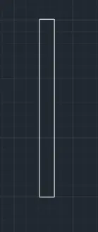
- next by using the rectangle command in autocad draw a rectangle in the fourth cloumn and then give the dimensions as per the table and the size of the column as per the table and then make it offset of that rectangle to make it offset and then offset dimensions is taken as per the table and make the circles by using the circle command and then copy all the circles and then make sure that copy that circles in the required places as per the table.
- and by using the multitext command or by copying the text which has been present in the another column the header text has been written or edited and edit the text as per the required and paste it on the row which has been present and edit the text and place the texting height as per the required table as shown in the figure below.
- draw and complete the table by using the command and then edit the tables by using multi text commands as shown in figure below.
- next by using the rectangle command in autocad draw a rectangle in the fourth cloumn and then give the dimensions as per the table and the size of the column as per the table and then make it offset of that rectangle to make it offset and then offset dimensions is taken as per the table and make the circles by using the circle command and then copy all the lines and then make sure that copy that circles in the required places as per the table.
- and draw the remaing lines by using the line command in the autocad and then copy the lines and place it as per the table.
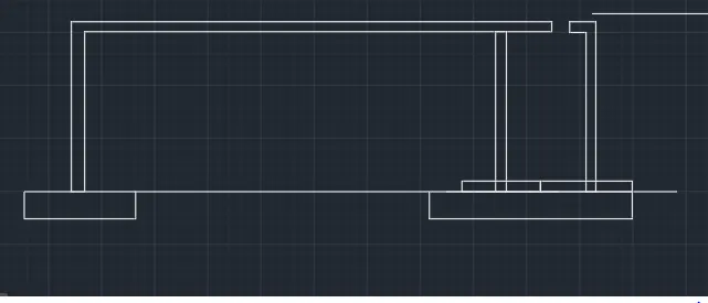
- taken in the line seetings select the required line type to change the line type.
- next make the offset of the line right corner of the rectangle to get the length of the another in the line seetings select the required line type to change the line type by using the offset command in autocad give the offset lenth as per the measurement taken in the line seetings select the required line type to change the line type.
- next make offset of that line ie the width of the inner wall is equal to per the measurement taken ie enter the offset command and give the width of in the line seetings select the required line type to change the line type
- place the columns as per the required places and then make that copy all the columns and rotate as per the required schdule column cross section placing.
- delete the unwanted lines by using the trim command in autocad in the line seetings select the required line type to change the line type.
- next make the offset of the line right corner of the rectangle to get the length of the another in the line seetings select the required line type to change the line type by using the offset command in autocad give the offset lenth as in the line seetings select the required line type to change the line type.
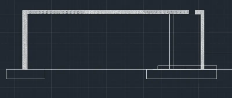
- next make the offset of the line left corner of the rectangle to get the length of the one of the liner lines of the column by using the offset command in autocad give the offset lenth as per the measurement taken in the line seetings select the required line type to change the line type.
- next make the offset of the line right corner of the rectangle to get the length of the another in the line seetings select the required line type to change the line type by using the offset command in autocad give the offset lenth as per the measurement taken in the line seetings select the required line type to change the line type.
- next make offset of that line ie the width of the inner wall is equal to per the measurement taken ie enter the offset command and give the width of in the line seetings select the required line type to change the line type
- place the columns as per the required places and then make that copy all the columns and rotate as per the required schdule column cross section placing.
- delete the unwanted lines by using the trim command in autocad in the line seetings select the required line type to change the line type.
- next make the offset of the line right corner of the rectangle to get the length of the another in the line seetings select the required line type to change the line type by using the offset command in autocad give the offset lenth as in the line seetings select the required line type to change the line type.
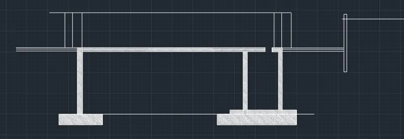
- next make the offset of the line left corner of the rectangle to get the length of the one of the liner lines of the column by using the offset command in autocad give the offset lenth as per the measurement taken in the line seetings select the required line type to change the line type.
- next make the offset of the line right corner of the rectangle to get the length of the another in the line seetings select the required line type to change the line type by using the offset command in autocad give the offset lenth as per the measurement taken in the line seetings select the required line type to change the line type.
- next make offset of that line ie the width of the inner wall is equal to per the measurement taken ie enter the offset command and give the width of in the line seetings select the required line type to change the line type
- place the columns as per the required places and then make that copy all the columns and rotate as per the required schdule column cross section placing.
- delete the unwanted lines by using the trim command in autocad in the line seetings select the required line type to change the line type.
- next make the offset of the line right corner of the rectangle to get the length of the another in the line seetings select the required line type to change the line type by using the offset command in autocad give the offset lenth as in the line seetings select the required line type to change the line type.
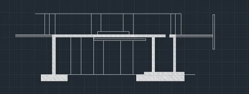
- next by using the rectangle command in autocad draw a rectangle in the fourth cloumn and then give the dimensions as per the table and the size of the column as per the table and then make it offset of that rectangle to make it offset and then offset dimensions is taken as per the table and make the circles by using the circle command and then copy all the circles and then make sure that copy that circles in the required places as per the table.
- and by using the multitext command or by copying the text which has been present in the another column the header text has been written or edited and edit the text as per the required and paste it on the row which has been present and edit the text and place the texting height as per the required table as shown in the figure below.
- draw and complete the table by using the command and then edit the tables by using multi text commands as shown in figure below.
- next by using the rectangle command in autocad draw a rectangle in the fourth cloumn and then give the dimensions as per the table and the size of the column as per the table and then make it offset of that rectangle to make it offset and then offset dimensions is taken as per the table and make the circles by using the circle command and then copy all the lines and then make sure that copy that circles in the required places as per the table.
- and draw the remaing lines by using the line command in the autocad and then copy the lines and place it as per the table.
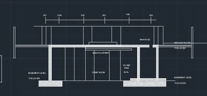
- To make the table as a single block then select the block option and create the block to create the block select on create block on view option and then for creating a block we have to pick the point ie the reference point and then select the lines or the objects which has to make block and then if we want to make annotative make annottive and then press ok.
- here to create block click on create block option and create the block name in the block name option then pick up the reference point and then slect the texts and lines which have to make block and then press ok to crate the block.
- Now, you need to tell AutoCAD what the insertion point should be. In other words, when you place the block, the point about which the block appears at your cursor Click the Select Objects button and select the objects you want to be stored in the block.
- To make the table as a single block then select the block option and create the block to create the block select on create block on view option and then for creating a block we have to pick the point ie the reference point and then select the lines or the objects which has to make block and then if we want to make annotative make annottive and then press ok.
- here to create block click on create block option and create the block name in the block name option then pick up the reference point and then slect the texts and lines which have to make block and then press ok to crate the block.
- Now, you need to tell AutoCAD what the insertion point should be. In other words, when you place the block, the point about which the block appears at your cursor Click the Select Objects button and select the objects you want to be stored in the block.
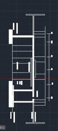
- Open the drawing of INDUSTRIAL SECTION which is already drawn in the challenge 9.
- In the left corner of the auto cad there is the tab named model. In the right side of the model tab there is a tab named layout.
- Left click on the layout and create new layout. Then open the new layout created. Rename the layout as section layout.
- Now enter command page setup manager. A new window of page setup will be opened. Modify the layout.
- Select printer as DWG to PDF.
- Elect paper size as A4. And click OK.
- Enter the command as VIEWPORTS.
- A window of view ports will be appearing on the screen.Select the viewport type as THREE; ABOVE and enter ok.
- Then specify the first corner point at the left top of the page and drag to another corner point in the right bottom of the page.
- Using the MS command zoom the views as desired of the section.