Creation of Multiple viewports, Scaling the drawing and setting in Template in AutoCad
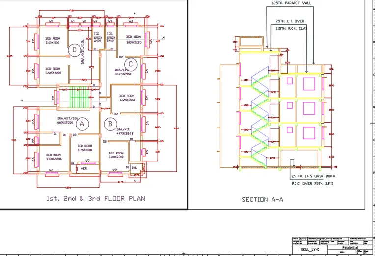
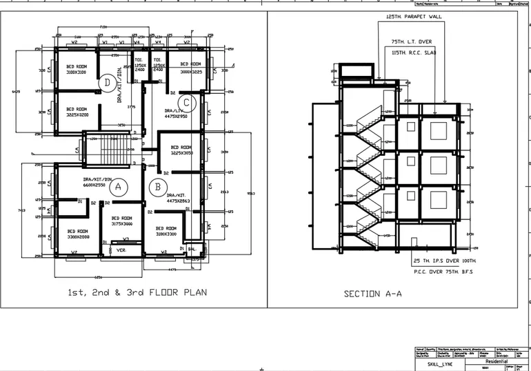
1.Create a layout of the Plan and Section A of the project in Challenges 7, using the template Tutorial-mArch.dwt in a scale as given in the Figure. Use the MV command to create the viewport of the size as shown in Figure. Also, use ATTEDIT command to edit the information in the title block. Use A1 size for the layout,Take a plot.
AIM :- To create a layout of the Plan and Section A-A of the Challenge of week 7, using the template Tutorial-mArch.dwt in a scale as given
in the question figure using AutoCAD.
INTRODUCTION :
1) Layout :
- Layout viewports are objects that display views of model space.
- One can create, scale, and place viewport in paper space on a layout.
- On each layout, one can create one or more layout viewports.
- Each layout viewport is like a closed circuit TV monitor of a view of the model at a scale and orientation that user specify.
2) Plotting drawing
- Plot command is used to print the file or drawing in AutoCAD.
- Plots the view in the current viewport on the Model tab or the current view in the layout, depending on which tab pu select to plot.
- Plots all of the objects in the current viewport, except objects on frozen layers. From a layout tab, all the geometry in paper space is plotted.
PROCEDURE :-
STEP 1
- Open AutoCAD application.
- Type "Un" and press enter.
- Set Units to scale inserted content as "milimeter" and press Enter.
- Sets limits by typing "limits" in command box.
STEP 2
- Importing Drawing from Challenge of week 7
- Type xref in command box and press enter.
- Click on "Attachement".
- Keep scale as 1.
- Click on insertion point as specify on screen.
- Click on okay and specify the point of insertion.
- Right click on the W7Q1 drawing and select the bind option.
- In pop up click on insert the drawing into 'Av'VIOQ1" along with layers.
Step 3 :-
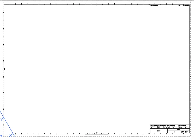
- Creating Layout
- Go to laYut tab and delete the current viewports available.
- Right click on the layout tab.
- Click on 'From template'.
- From pop up click on 'Tutorial -mArch'.
- Right click on layout and click on rename and type "Floor Plan-Section A-A".
STEP 4
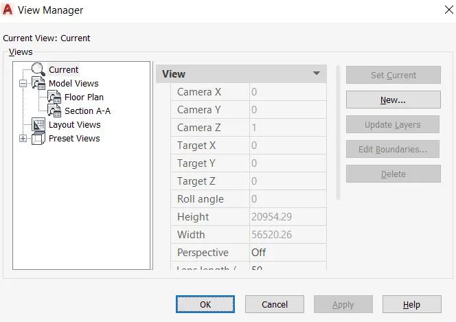
- Creating Views
- Go to model tab.
- Type V and press enter.
- Click on new.
- Type name as "Floor Plan".
- Click on define window.
- Select the Floor Plan.
- Click on new.
- Type name as "Section AA".
- Click on define window.
- Select the Section view.
STEP 5 :-
- Creating Viewports
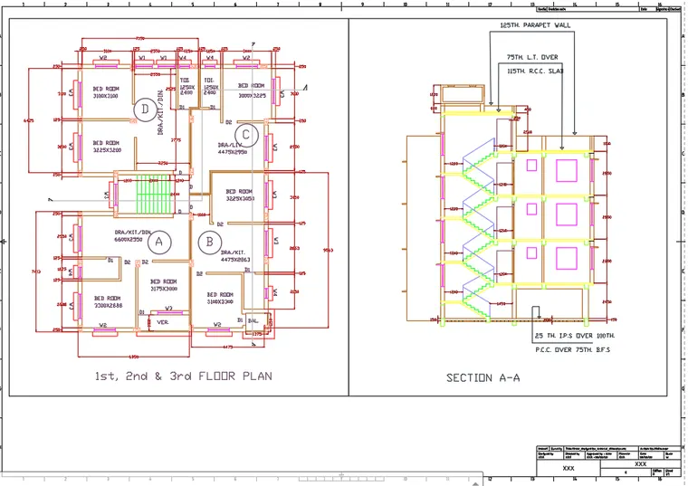
- Draw rectangle from the top of layout of dimensions 400mm x 445mm.
- Draw another rectangle adjacent to the rectangle from the top right corner with dimensions 375mm x 445mm.
- Type "PS" and press enter to go to paper space.
- Type "MV" in command box and click on object in command box.
- Select the first rectangle drawn as object to viewport.
- Type "MS" and press enter to go to model space.
- Type "V" and press enter.
- Select the Floor Plan view created and click on set current and then click okay.
- Change the scale to 1:50/2%.
- Type "PAN" in the command box and press enter and adjust the figure in viewport.
- Type "PS" and press enter to go to paper space.
- Type "MV" in command box and click on object in command box.
- Select the second rectangle drawn as object to viewport.
- Type "MS" and press enter to go to model space.
- Type "V" and press enter.
- Select the Section A-A view created and click on set current and then click okay.
- Change the scale to 1:50/2%.
- Type "PAN" in the command box and press enter and adjust the figure in viewport.
- Type "PS" and press enter to go to paper space.
- Select the two viewports created and go to properties.
- Change the display locked to "YES".
STEP 6:-
- Changing layers property
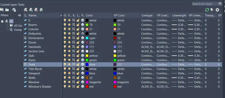
- Type "LA" in the command box and press enter.
- Change the colour property of Layers of viewport 1 and 2 for better visibility.
- Layers for Viewport 1 & 2 respectively are as follows.
STEP 7:-
- Adding Details to Template
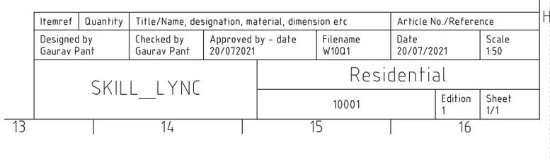
- For changing the data of the attribute goto BATTMAN or double to enter the value.
- Change the values as per the question requirement.
- Give dimensions of the view ports and text regarding scale as 1:50.
STEPS: 8
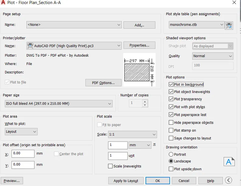
- Type plot and press enter.
- Set name as "Week_10_Q1".
- Change printer to AutoCAD PDF.
- Set paper size as ISO A1.
- Change plot area to "Layout".
- Change plot style table to "monochrome.ctb"
- Check the preview for adjustments.
- Click "0K" on the plot box.
- Select the path and set name.
Result :-
- The result of this question consists of layout of floor plan and section A-A created from standard AutoCAD template 'Tutorial-mArch".
2.Create a layout of the Kitchen drawn in Challenge 9 as shown in Figure. use the scale as shown in the Figure. Use A4 Size page for the layout,Take a plot.
AIM: To create the layout of the kitchen and providing hatches to it using the autocad in detail using A4 size for layout.
INTRODUCTION:
1) Layout :
- Layout viewports are objects that display views of model space.
- One can create, scale, and place viewport in paper space on a layout.
- On each layout, one can create one or more layout viewports.
- Each layout viewport is like a closed circuit TV monitor of a view of the model at a scale and orientation that user specify.
PROCEDURE:
STEP 1:
- Open AutoCAD application.
- Type "Un" and press enter.
- Set Units to scale inserted content as "milimeter" and press Enter.
- Sets limits by typing "limits" in command box.
STEP 2:
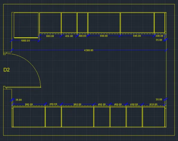
- Below counter plan:
- First draw the line horizontally with the length of 4300mm.
- Next draw another line from the previous line with the length of 3200mm vertically upwards.
- Next again draw the line from previous line with the length of 4300 mm horizontally backwards at the top.
- Next have to join the first line and the last line which we have drawn previously.
- Next offset the four sides with the offset of 20mm outside.
- Next offset the line inside with the offset command with the length of 600mm, including the fridge.
- Afterwards we draw the fridge separately with other dimensions in the kitchen layout.
- Next draw the line opposite side to create the parts of kitchen.
- Next divide the seven parts downside with different dimensions compared to the upper side portion.
- Next leave the space left and right corners with the length of 35mm at the top and bottom.
- Next put the dimensions for the every part in the diagram.
- Next indicate the door as D2.
STEP 3:
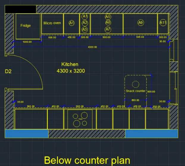
- Next use the single text command
- indicate the parts where ever it requires with single text command.
- put the dimensions for the every part in the diagram.
- Next draw the snack counter with the length of 600mm and width of 900mM.
- draw the circles to create the hub in the middle at the bottom of the kitchen.
- create the windows using the line command and trim command.
Step:-3
- Firstly select the layout at left side corner of the screen.
- After selecting the layout rename the layout as floor plan.
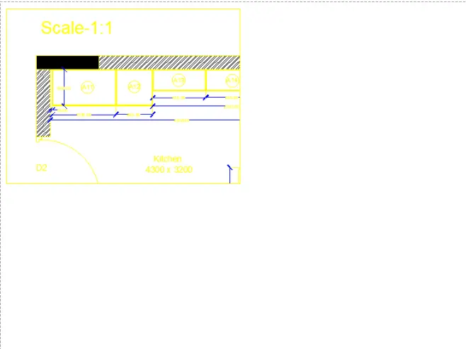
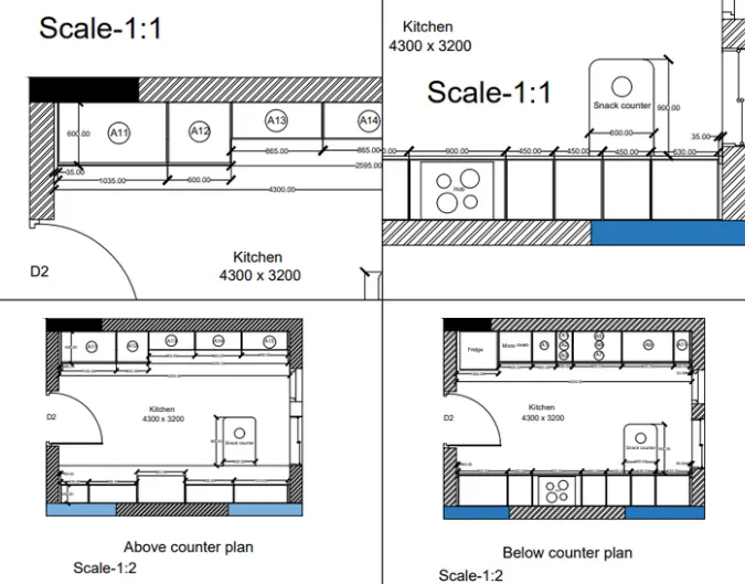
- Next create the 1st view using the MV command, that we take the scale as 1:1.
Step:-4
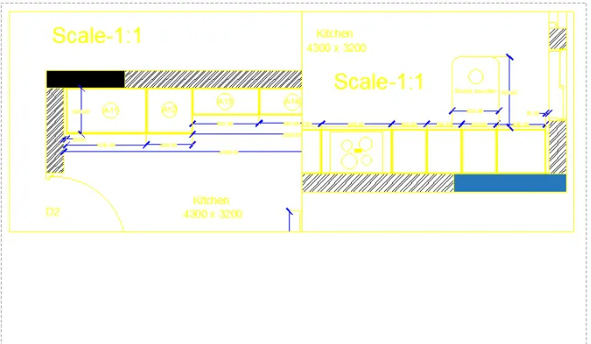
- Next we create the 2nd view using the MV command, that we take the scale as 1:1.
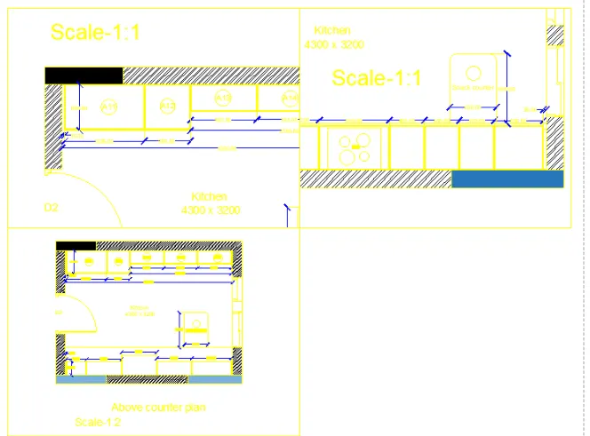
- create the 3rd view using the MV command, that we take the scale as 1:2.
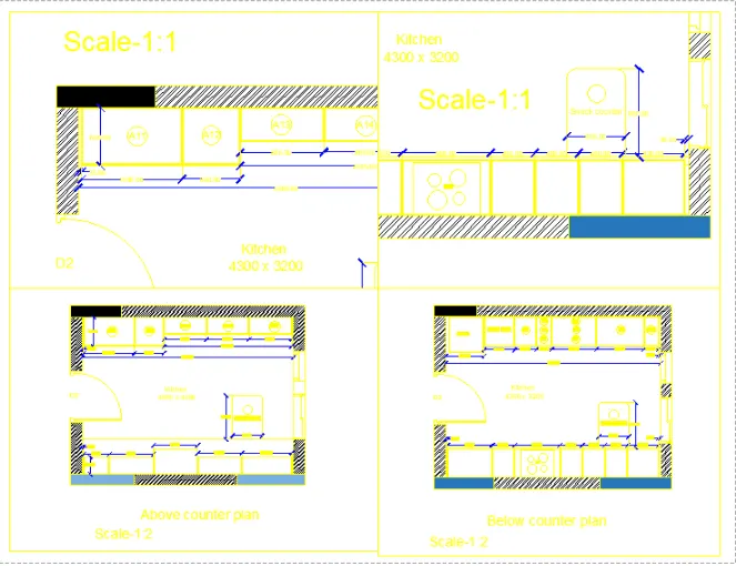
- Next create the fourth view using MV, command ,that we take the scale as 1:2
Step:-5
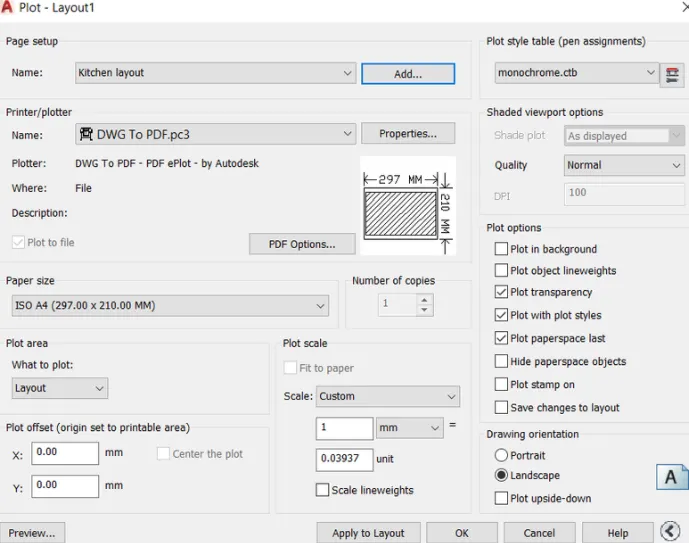
- finally we convert the drawing file into a pdf file using plot command.
Step:-6
- Next select the A1 paper size fot fit the drawing in the paper as shown in the below figure.
- Next select the pen assignments as monochrome.ctb.
- Then select the apply to laput and click the 0k option.
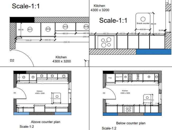
- Then finally the dwg file is exported to the pdf file as shown in the below figure.
RESULT
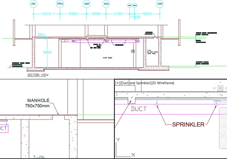
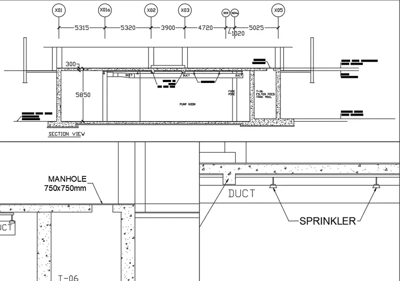
3.Create a layout of the section created in Challenges 9.Use scale as mentioned in the Figure. Use MV command create multiple viewports. Take a plot.
Aim :- To create a layout of the section created in Challenge of week 9, use scale as mentioned in the question Figure and take a plot by using AutoCAD.
Procedure :-
STEP 1
- Open AutoCAD application.
- Type "Un" and press enter.
- Set Units to scale inserted content as "milimeter" and press Enter.
- Sets limits by typing "limits" in command box.
STEP 2
- Importing Drawing from Challenge of week 9
- Type xref in command box and press enter.
- Click on 'Attachement
- Keep scale as 1.
- Click on insertion point as specify on screen.
- Click on okay and specify the point of insertion.
- Right click on the W9Q3 drawing and select the bind option.
- In pop up click on insert the drawing into W10Q3 along with layers.
STEP 3 :-
- Creating Layout
- Go to layout tab and delete the current viewports available.
- Right click on the layout tab.
- Click on rename and type "Industrial Building section layout".
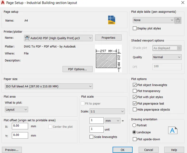
- Go to page setup manager.
- Click on new.
- Set name as A4.
- Change printer to AutoCAD PDF.
- Set paper size as ISO full bleed A4.
- Change plot area to "Layout".
- Click "ok"
STEP 4 :-
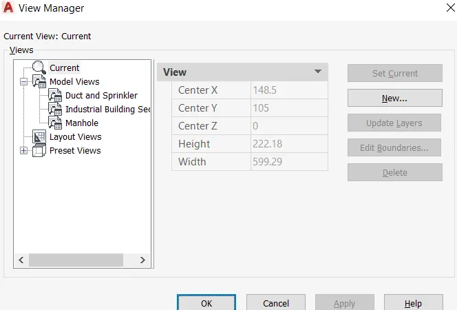
- Creating Views
- Go to model tab.
- Type "V" and press enter.
- Click on new.
- Type name as "Industrial Building Section".
- Click on define window.
- Select the entire drawing to fit
- Click on new.
- Type name as "Manhole".
- Click on define window.
- Select the area around the manhole.
- Click on new.
- Type name as "Duct and Sprinkler".
- Click on define window.
- Select the area around the middle sprinkler and right duct.
STEP 5:-
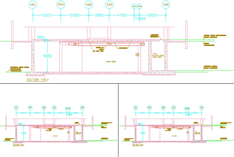
- Creating Viewports
- Type 'm' and press enter.
- Click on Layer 3 option in the command box and press enter.
- Specify the corner points of view port.
- Type "MS" and press enter to go to model space.
- Enter viewport arrangement as "Above".
- Type "F" to fit the viewport.
- Type "MS" and press enter to go to model space.
- Click inside of top viewport.
- Type "V" and press enter.
- Click on "Industrial Building" and click on set current.
- Change the scale to 1:100.
- Click inside of bottom left viewport.
- Type "V" and press enter
- Click on "Manhole" and click on set current.
- Change the scale to 1:30.
- Click inside of bottom right viewport.
- Type "V" and press enter.
- Click on "Duct and sprinkler" and click on set current.
- Change the scale to 1:30.
Step 6:-
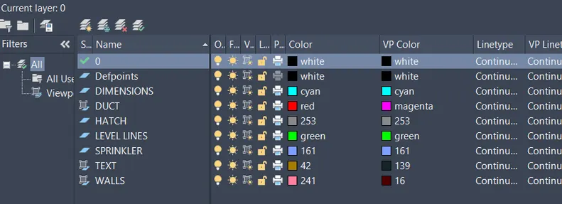
- Changing Viewport Layers
- Type "LA" in the command box and press enter.
- Change the colour property of Layers of all four viewport for better visibility.
- Layers for all Viewports respectively are as follows.
.
STEP 7
- Plotting
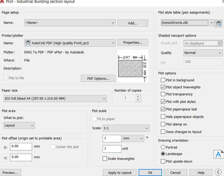
- Type "plot" and press enter.
- Set name as Industrial_Building_Layout.
- Change printer to AutoCAD PDF.
- Set paper size as ISO full bleed A4.
- Change plot area to "Layout".
- Change plot style table to "monochrome.ctb"
- Check the preview for adjustments.
- Click "0k" to plot.
- Select the path and set name.
RESULT