Creation of Multiple viewports, Scaling the drawing and setting in Template in AutoCad
Initial Procedure:
- Open AutoCad
- Select the metric system
- Select the Units and selecting decimals with precision 0,0
- Set the Limits, as lower limits 0,0 and upper limits 1000,1000
- Now in the command prompt, command, ZOOM and select All.
1.
Aim:
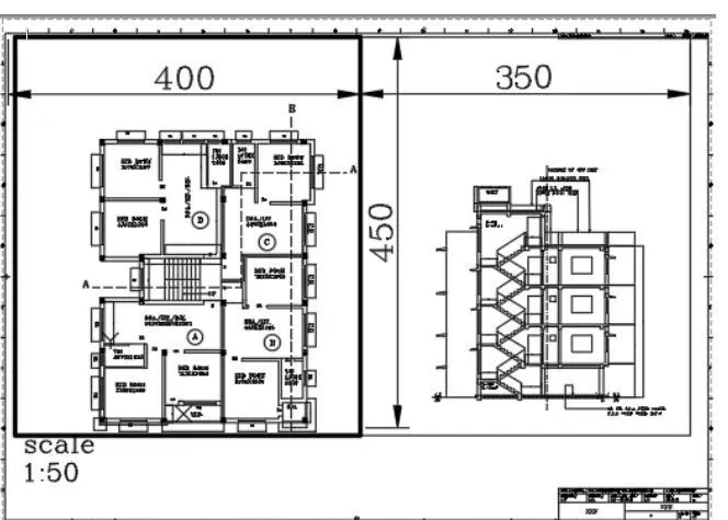
- To create a layout of the plan and Section A of the project in Challenges 7, using the template Tutorial-mArch.dwt in a scale as given in the figure.
- To use the MV command to create the viewport of the size as shown in Figure.
- To use ATTEDIT command to edit the information in the title block and to use A1 size for the layout.
Procedure:
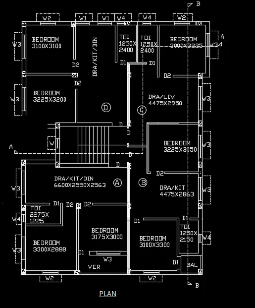
- Draw constructions lines vertically and horizontally using the command, XL-V and XL-H, and give the thickness of the wall, as outer wall thickness as 250mm and inner wall thickness as 125mm
- Now, using OFFSET command, offset 3100 horizontally and 3100 vertically for the bedroom
- Now OFFSET horizontally 2550, 125, 1250 (for toilet), 125, 125, 1250, 3000, 250mm
- Now OFFSET vertically, 2950mm from the bedroom of C and give wall thickness of 125mm, 3250mm and 3200mm. Also give the wall thickness as 250mm
- Divide the rooms horizontally by offsetting 3225mm, 125mm, 3250mm, 125mm, 4475mm and 250mm
- Now OFFSET 2400mm vertically and 4400mm horizontally for the staircase.
- Using OFFSET command, offset 3050mm vertically from drawing of C and 3225mm horizontally for the bedroom of B and offset the wall thickness too.
- Now using OFFSET command, offset 3300mm vertically and 3100mm horizontally for the front bedroom.
- Fillet the wall of the Bedroom with the left side wall and give wall thickness of 250mm
- Now offset 100mm from the outer wall and sketch verandah by offsetting 1000mm and offset 3175mm for the bedroom of A.
- Using OFFSET command, offset 2888mm for the front bedroom of A and offset wall thickness of 125mm
- Offset 1225mm and 2275mm for the toilet, then offset 2550mm for the drawing/kitchen/dining of A
- Fillet all the corners and trim the unwanted lines using TRIM command.
- For creating doors and windows, we assume the sizes as: D=1000*2100mm D1=700*2100mm D2=900*210mm W=600*1200mm W1=900*1200mm W2=1000*1200mm W3=1500*1200mm W4=500*500mm
- Now trim off the size of the doors on the walls, where ever provision for door is given.
- Now create the windows of given sizes and place it in respective places.
- Using Multiline text, create text box, select the text style and height and type the required text, along with the name of the rooms with sizes and marking of windows and doors.
- Using the TRIM command, trim off the unwanted lines
- Draw the windows using the LINE command.
- HATCH command is used to hatch the required areas.
- Using TEXT, required texts are marked and placed at appropreate areas.
- Using LINETYPE, the continuous lines can be converted to dotted lines.
For sketching section A-A
Before sketching the section.
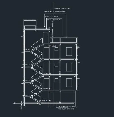
- Assume Slab thickness=100mm
- Assume Beam=300*350mm
- Assume Lintel level from the floor= 2100mm
- Assume Lintel thickness=150mm
- Assume Staircase waist slab thickness and landing slab thickness=100mm
- Assume Height of newel post=1000mm
- Now extend the wall thickness wherever the section cuts the plan and draw a horizontal line to show the ground level.
- Now draw a 150mm thickness from the ground level by offsetting 150mm from ground level
- Using OFFSET command, offset a distance of 2450mm from the ground level for the ground floor height.
- Now offset a 100mm from the top level for slab thickness.
- Draw the beams of 300*350mm wherever the walls are there and colums of 400*300mm width.
- HATCH command is used to hatch the required areas.
- Using TEXT, required texts are marked and placed at appropreate areas.
- Using LINETYPE, the continuous lines can be converted to dotted lines.
- Now draw a beam of 300 mm width and 270mm depth down the ground level.
- Draw a vertical line of 143.75mm as riser, except on the top floor, at a distance of 1450mm from the 300mm and a horizontal line of 250mm.
- Similarily draw 8 steps, draw the landing from the 8th one and offset a thickness of 100mm downwards.
- Draw an inclined line joining the riser end of the flight and offset 100mm from that line and join it with the landing slab. Mirror the steps to the opposite side meeting the next floor, given dotted lines as it is invisble.
- Now draw a beam of 300*250mm as landing beam.
- For the first floor, offset a height of 2850mm, also provide slab thickness of 100mm and beam of 300*350mm
- Extend the projected walls of 125mm and 250mm.
- Now extend the doors and windows from the plan to get its width, then a height of 1200mm for window and 50mm for ventilator is provided.
- Now sketch the lintel slab of 150mm and projection of shade of 400mm is made
- Section of the window on one end of the wall and the stair side is shown, as it is cut through by the section line.
- HATCH command is used to hatch the required areas.
- Using TEXT, required texts are marked and placed at appropreate areas.
- Using LINETYPE, the continuous lines can be converted to dotted lines.
- Now in the command prompt, Using LAYOUT, select Template,then Tutorials M-arch.dwt.file
- Now go to Layout and Using MV command, viewports of 400*450 and 350*450mm are created
- Adjust the drawings and scale to 1:50
- Now usinf FIELD command, select the viewport as object and set the custom scale
- Double click on the viewport made to edit the information and to write anything more
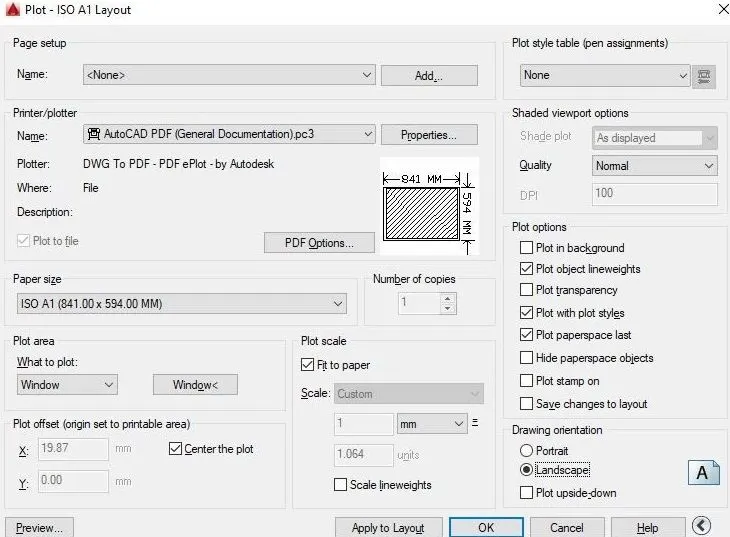
- Now select Insert layout, layout name and then select ISO A1 layout. Click OK
- Now click ctrl+P to select the plot,
- Select the paper size ISO A1 and plot the area and select the requied window in layout, click on the center of the paper and fit to paper and in landscape
Result:
2.
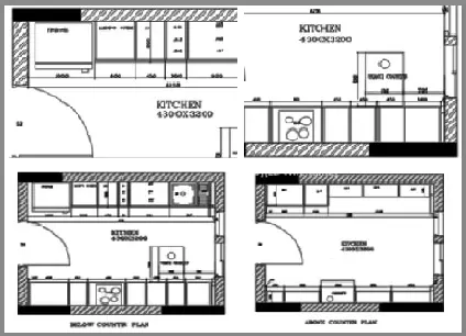
Aim: To create a layout of the Kitchen drawn in Challenge 9 as shown in Figure and to use the scale as shown in the Figure and to use A4 Size page for the layout of the plot.
Procedure:
- A rectangle of 4734*3688mm is made using RECTANGLE command and now draw a horizontal and a vertical line using XLINE command
- Now offset the rectangle first with a distance of 230mm.
- Now offset 350,450,900,450,450,560 and 35 horizontally and 600mm vetically
- Offset 700 distance from the right wall horizontally and 900mm vertically for snack counter
- For working platform1, offset 35,965,600,2595 and 35 horizontally and 600, 350mm vertically.
- For Working platform2, offset 35,450,900,900,900,1010 and 35 horizontally and 350mm vertically.
- Offset 12mm on both sides to the main offsetted lines to dimension it centre to centre
- Using ARC and LINE commands, the doors are created
- Now using the RECTANGLE command and PLINE command to draw, fridge, sink, chimney is created
- Using CIRCLE command, sink hole, snack counter, hob, chimney is made.
- Now again using OFFSET command, draw Micro oven and other utilities.
- Using LINETYPE, we can change the continuous line to dash lines and can change the scale accordingly.
- Use the TRIM command to trim off the unwanted lines.
- Using TEXT, we can insert the required text in the appropreate space and finally dimensioning is done.
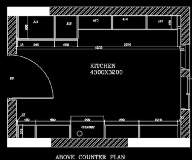
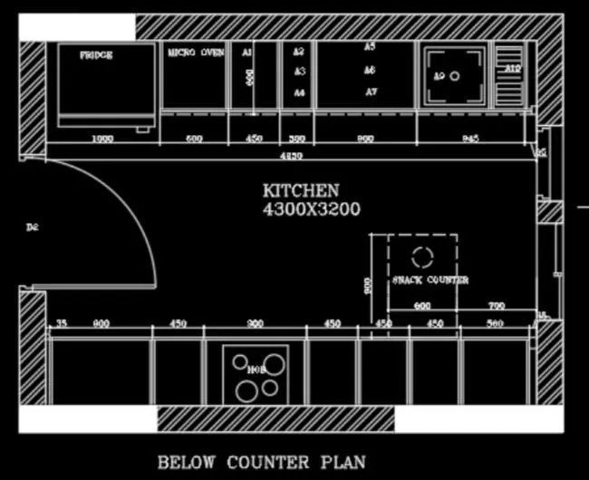
- Now in the command prompt type ps and ms to adjust the view
- Go to the layout and command MV and draw 4 viewport
- Now adjust the scale and command field and select object and custom scale and set scale.
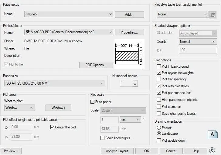
- Select single plots and press ctrl + P
- Now give any printer name and select the paper size ISO A4 and click on the center of the paper to fit the paper and select landscape mode
Result:
3.
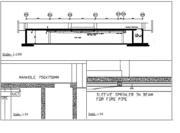
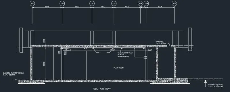
Aim: To create a layout of the section created in Challenges 9 and to scale as mentioned in the figure given. Using MV command to create multiple viewports.
Procedure:
- Use PLINE command to start drawing the sectional view of the building, the ducts are drawns with LINE command
- For easy drawing of the ducts with the required size, RECTANGLE command is used .
- Using the LINETYPE, the continuous lines are converted to dotted lines and scale can be adjusted.
- Now Start hatching the section using HATCH command, Soild and AR-CONC for the concreted areas
- Using TEXT, we can insert any text of desired size and style at appropriate place.
- Dimensioning can be done finally.
- Now in the command prompt type ps and ms to adjust the view
- Go to the layout and command MV and draw 4 viewport
- Now adjust the scale and command field and select object and custom scale and set scale.
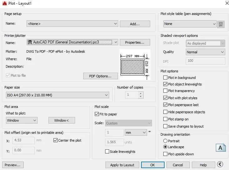
- Select single plots and press ctrl + P
- Now give any printer name and select the paper size ISO A4 and click on the center of the paper to fit the paper and select landscape mode
Result: