Creation of Multiple viewports, Scaling the drawing and setting in Template in AutoCad
AIM: To create a layout of the Plan and Section A of the project in Challenges 7, using the template Tutorial-mArch.dwt in a scale as given in the Figure.
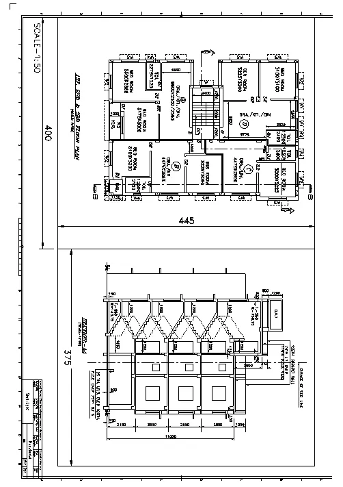
INTRODUCTION: Autocad is a software well designed for drawing 2D and 3D plans for the strutcure designs.
PROCEDURE:
1. CAD software is opened and then the process starts.
2. A new layout is now created using the command LAYOUT and select template and as required mArch.dwt template was selected and delete the exisiting viewport.
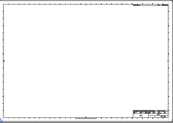
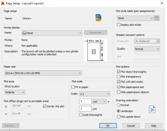
3. Right click on the layout and select page setup manager and modify the settings as required.
4. REC command is used and two rectangles of equal sizes are drawn that fits in the paper.
5. Now click MV and select object as these rectangles and in this way two model spaces was created.
6. V command is used by typing in the command bar to open the view manager.
7. Select the required models V1 and V2 and apply it in both the rectangles.
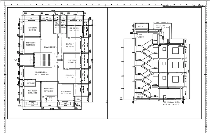
8. ATTEDIT is used to open the edit attributes dialogue box and apply the required comments and click ok.
9. PLOT is used to open the page setup manager the following settings was applied and click the preview option at botton.
RESULTS: Layout are created as per the figure using autocad software.
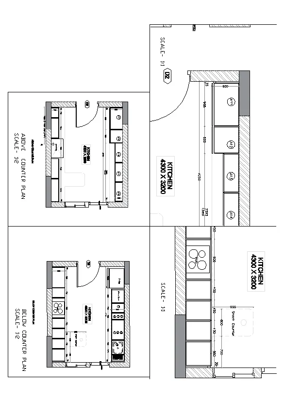
AIM: To create a layout of the Kitchen drawn in Challenge 9 as shown in Figure. Use the scale as shown in the Figure.
INTRODUCTION: Autocad is a software well designed for drawing 2D and 3D plans for the strutcure designs.
PROCEDURE:
1. CAD software is opened and then the process starts.
2. A new layout is now created using the command LAYOUT and delete the exisiting viewport.

3. Right click on the layout and select page setup manager and modify the settings as required.
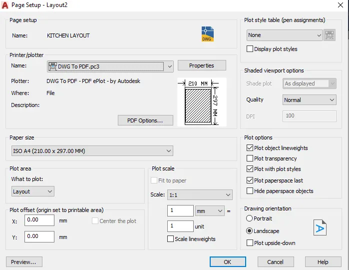
4. REC command is used and four rectangles of equal sizes was drawn so that it will fit in the paper.
5. MV command is used and objects are selected as these rectangles.
5. Now four model spaces are created.
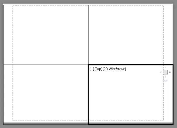
6. V command is typed in command bar to open the view manager.
7. The required models like V1, V2, V3 and V4 are choosen and applied them in the respective rectangles.
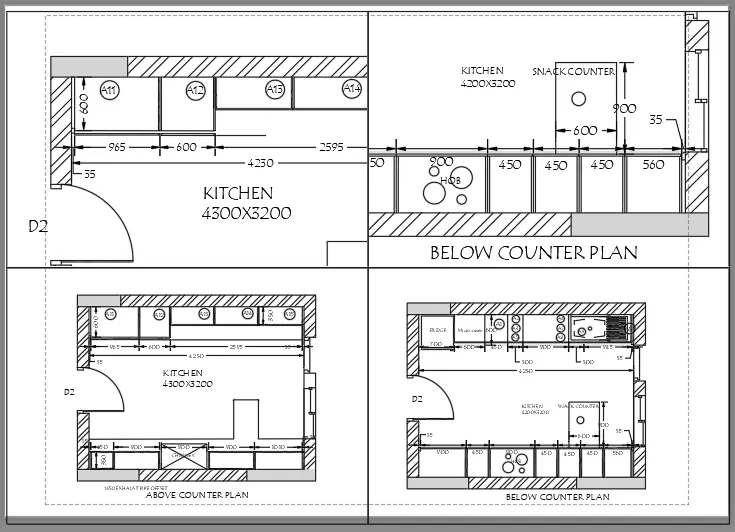
8. PLOT is used to open the page setup manager the following settings was applied and click the preview option at botton.
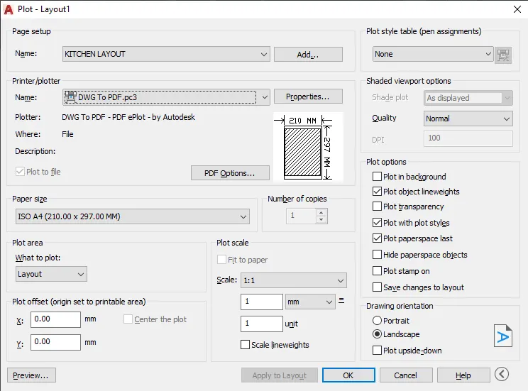
9. The preview of the whole drawing is shown in below figure.
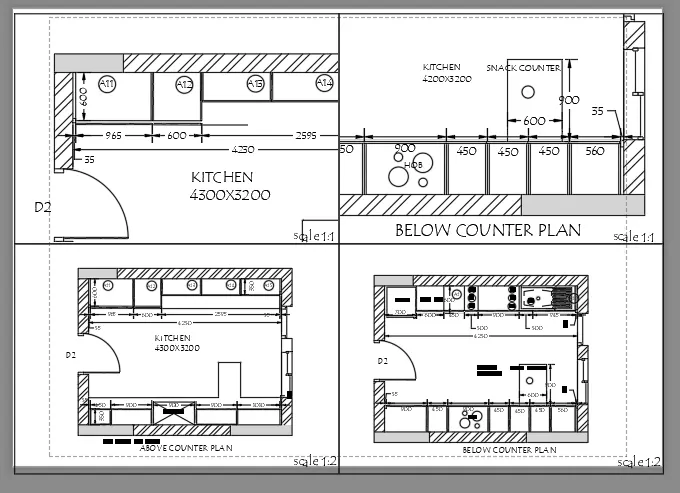
RESULTS: Kitchen layouts are created as per the figure using autocad software.
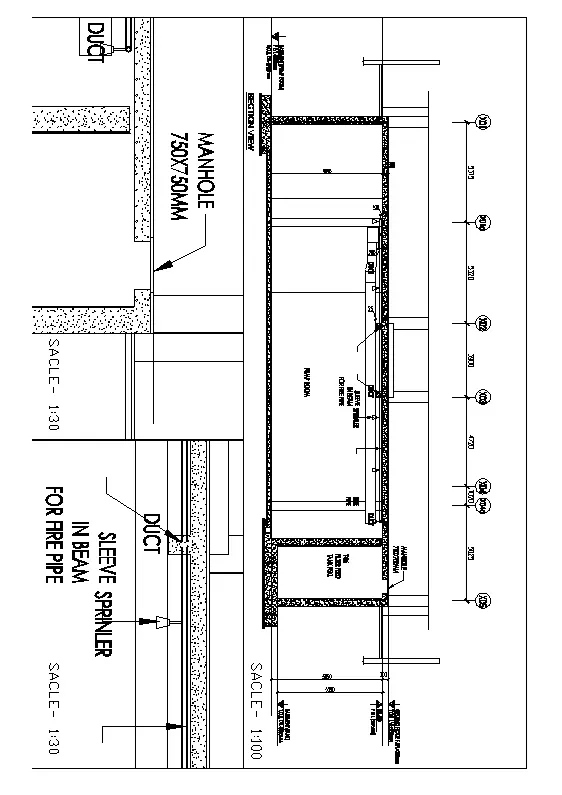
AIM: To create a layout of the section created in Challenges 9.
INTRODUCTION: Autocad is a software well designed for drawing 2D and 3D plans for the strutcure designs.
PROCEDURE:
1. CAD software is opened and then the process starts.
2. A new layout is now created using the command LAYOUT and delete the exisiting viewport.
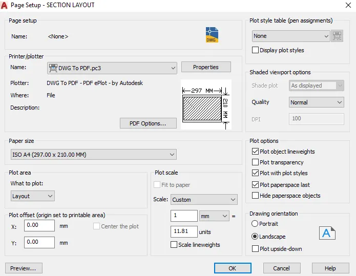
3. Right click on the layout and select page setup manager and modify the settings as required.
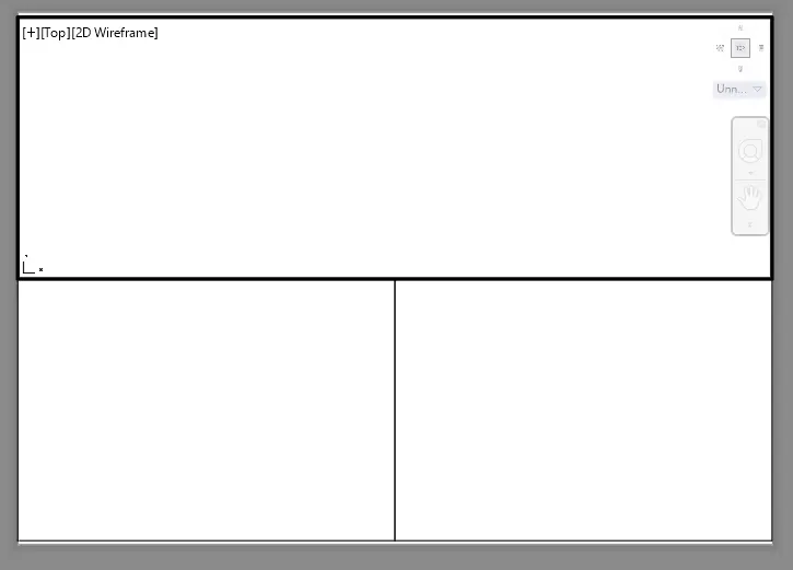
4. REC command is used to draw three rectangles of equal sizes was drawn that fits in the paper.
5. MV command is used and objects are selected as these rectangles and in this way three model spaces was created.
 |
6. V command is used to open the view manager.
7. The required models V1, V2 and V3 are selected and apply it in the respective rectangles.
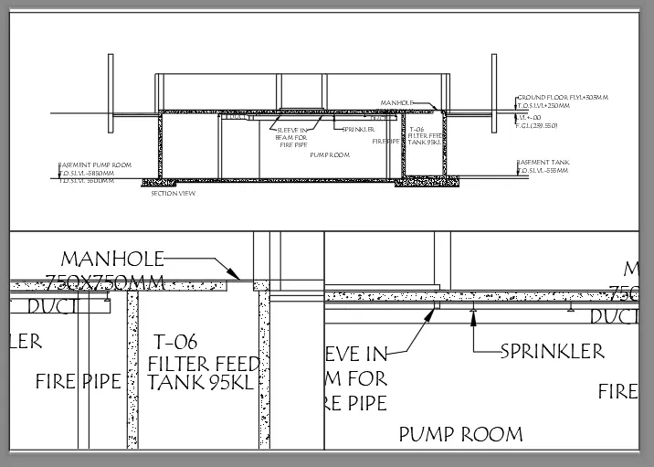
8. PLOT command is used to open the page setup manager the following settings was applied and click the preview option at botton.
9. The preview of the whole drawing is as shown.
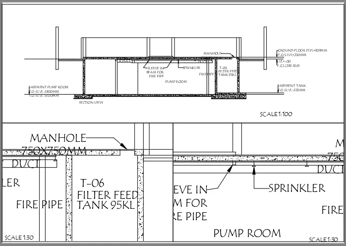
RESULTS: Layout of given section was created as per the figure using autocad software.