Creation of Multiple viewports, Scaling the drawing and setting in Template in AutoCad
AIM:
(a). Create a layout of the Plan and Section A of the project in Challenges 7, using the template Tutorial-mArch.dwt in a scale as given in the Figure. Use the MV command to create the viewport of the size as shown in Figure. Also, use ATTEDIT command to edit the information in the title block. Use A1 size for the layout. Take a plot.
(b). Create a layout of the Kitchen drawn in Challenge 9 as shown in Figure. Use the scale as shown in the Figure. Use A4 Size page for the layout. Take a plot.
(c). Create a layout of the section created in Challenges 9.
Use scale as mentioned in the Figure. Use MV command create multiple viewports. Take a plot.
INTRODUCTION:
- Above sketches are drawn by defining the page setup option in the task bar of the AUTOCAD Software before proceeding further for sketching.
- Instead of using first option, we may also select predefined layout size defined in LAYOUT Command in “template”.
- After giving Layout command, we will select several options given in the popup window at the command menu such as delete, Copy, new, template, rename, save as, set.
- we may also select "template" option given in "layout" command by defining the predefined size given in various M arch/I arch form as per the units assigned. (I stands for imperial units while m stands for metric units)
- Layout can be modified by clicking the right mouse button on the Layout icon given in the taskbar.
- All sketches are annotated with a scale as per the given requirement at the time of commencement of this challenge.
- At the time of plotting, we have defined the "DWG TO PDF.pc3" option with a scale of 1:1.
- In case of the Multiview screen, I have defined the multi screens through rectangular sketching followed by selecting "object" option given in the "MV" command.
- After selecting the View, we will use cautiously the "MS"& "PS" command within the LAYOUT window.
PROCEDURE:
FIGURE(a):
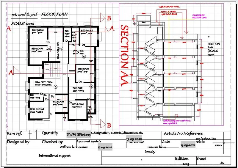
- Here we use the "rec" command to draw the view on an "ISO A1 standard" layout, defined using the "layout" command, followed by selecting the "template" option and then choosing the data as per the requirement given in question (a) from the upcoming popup window.
- After Drawing the rectangles of dimensions (400 & 375) units in the length form & defining the width arbitrarily, we will proceed by selecting OBJECT option in the MV command for allotting the view to that rectangle.
- After using the "MV" command, Use "MS" option to zoom in/out within the paper & use "PS" command to zoom in/out with the paper size.
- After setting the views using various option defined in the "MS" command given in the navigation toolbar, don't forget to lock that view using "lock" option given in the "MV" command.
- AFTER locking the views, plot the sketch by right clicking on the layout button in the taskbar.
- Draw the title block using the line command with arbitrarily dimensions & texting properties.
- Here I have used text height of 20 unit with "gabriola" style.
- After Drawing the block with requisite labelling/texting, use "ATTDEF" command to give the answers to the given labelling.
- After Defining the various text answers, create block by using "b" command.
- use "I" insert command to fill the title block as per the requirement.
FIGURE(b):
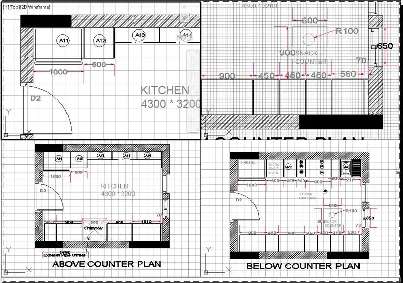
- Here we use the "rec" command to draw the view on an A4 sheet, defined using the "page setup" option, followed by selecting the "DWG TO PDF.pc3" option and then choosing the data as per the requirement given in question (b) from the upcoming popup window.
- After Drawing the four rectangles of equal dimensions arbitrarily, we will proceed by selecting "OBJECT" option in the "MV" command for allotting the view to that rectangle.
- After using the "MV" command, Use "MS" option to zoom in/out within the paper & use "PS" command to zoom in/out with the paper size.
- After setting the view using various option defined in the "MS" command given in the navigation toolbar, don't forget to lock that view using "lock" option given in the "MV" command.
- Before locking the views, it is better to scale annotatively in the model space and then, plot the sketch by right clicking on the layout button in the taskbar.
6.
FIGURE(c):
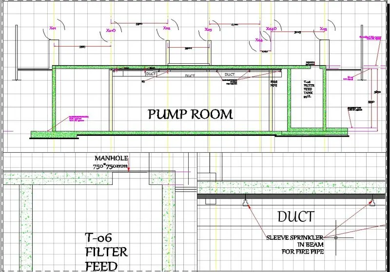
- Here we use the "rec" command to draw the view on an A4 sheet, defined using the "page setup" option, followed by selecting the "DWG TO PDF.pc3" option and then choosing the data as per the requirement given in question (b) from the upcoming popup window.
- After Drawing the three rectangles, we will proceed by selecting "OBJECT" option in the "MV" command for allotting the view to that rectangle.
- use "V" view command to define the various views required in the three rectangle and then name these views.
- Use "MS' command to work on a specific view and then by clicking on that rectangle, select the name of the view from the view manager in the view tab defined in the 3rd point.
- Don’t forget to annotate the required scale in the various views before proceeding for "LOCK" option given in the "MV" command.
- After locking all the views, plot the layout using the "PLOT" option with option introduced in the introductory part.
RESULT:
All the sketches are drawn in the Auto cad software and are attached here in the "PDF" form with the annotate scale mentioned at the commencement of sketching in the model space.