Creation of Multiple viewports, Scaling the drawing and setting in Template in AutoCad
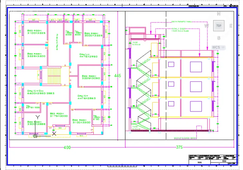
AIM: To create layout of the plan and section A of the project in challenge7 as shown in the figure
INTRODUCTION: The layout is created in AutoCAD by using the template Tutorial-mArch.dwt in a given scale
PROCEDURE:
- Open week 7 challenge in AutoCAD
- Zoom the Plan which is cover entire screen
- Click on the VIEW ribbon
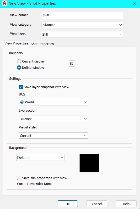
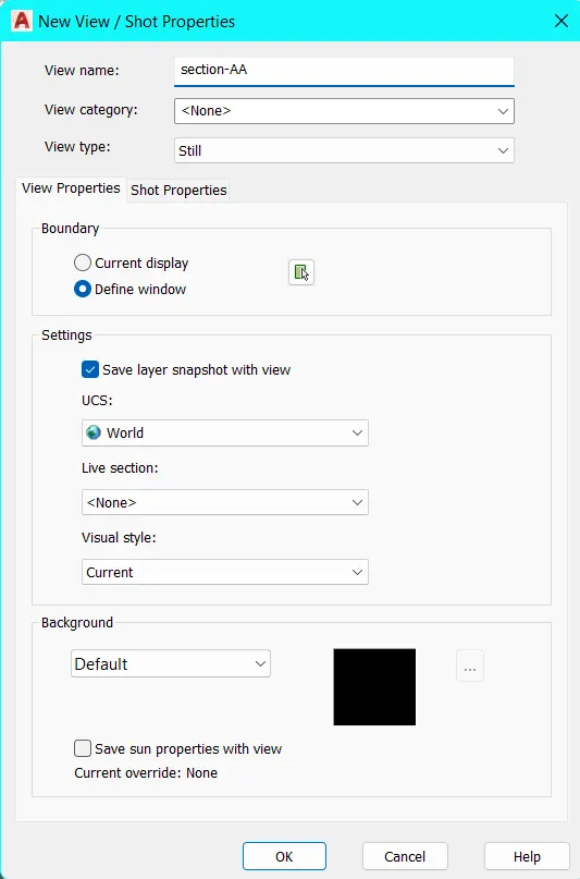
- In the NAMED VIEWS tool click on NEW VIEW
- A dialog box is opened
- Specify View Name as Plan
- Repeat for section A
- In the Model Viewports Tool
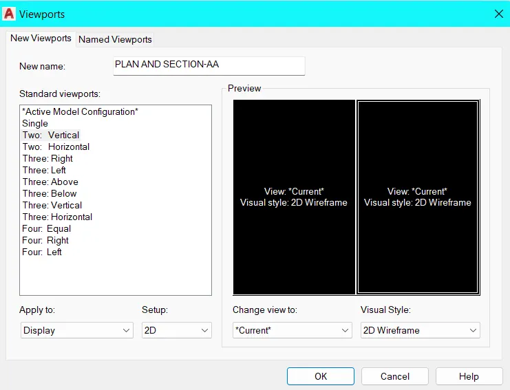
- Click to drop down Viewport Configuration and select TWO: VERTICAL
- Click on the NAMED, a dialog box open as viewports
- Go to new viewports tab and type new name as Plan and Section A-A
- Enter Layout command
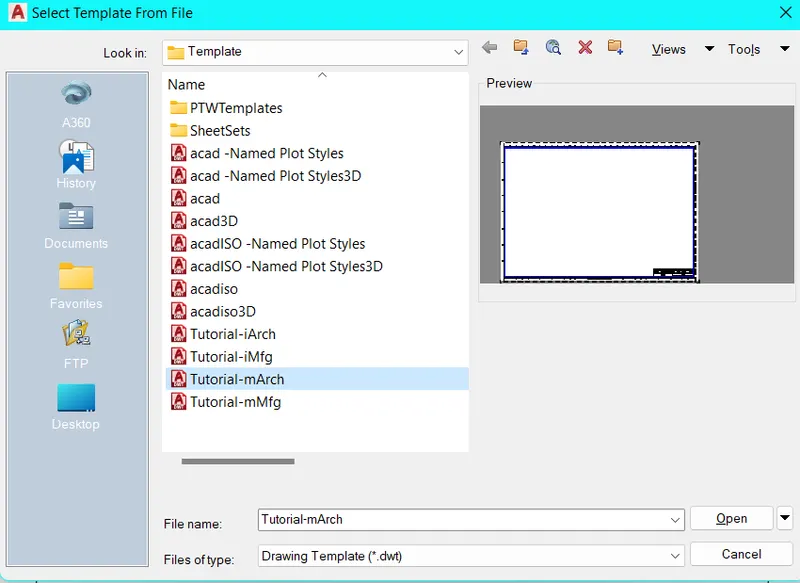
- Click on Template option
- Select Tutorial mArch and open
- Click OK in Insert Layout dialog box
- A model tab is added as ISO A1 Layout
- Right click on the ISO A1 tab to rename as Plan and Section A-A
- Enter PAGESETUP command
- A dialog box shows of Page Setup Manager
- Click on Modify
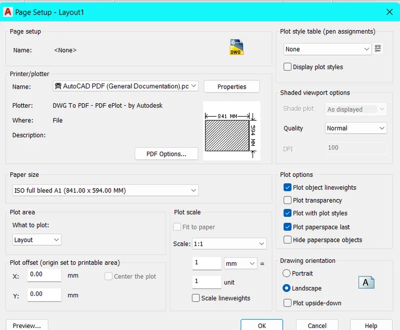
- New dialog box shows of Page Setup
- Change Printer/Plotter name as AUTOCAD PDF (General Documentation).pc3
- Change page size as ISO A1 (841.00 X 594.00 MM)
- Select to delete existing drawing in current page
- Set current layer as Title Block from layer property
- Enter REC command for rectangle
- Create two rectangles of size 400x445 and 375x445
- From the Layout ribbon go to Layout Viewports Tool and click on the INSERT VIEW icon
- Click on the Plan and place in the 1st rectangle
- Similarly click on the Section and place in the 2nd rectangle
- Click on Plan view port Unlock the viewport from status bar and change scale as 1:50
- After changing scale, plan viewport boundry streched to match rectangle corners Esc
- Simlarly for the Section Viewport
- Enter MS for Model Space or click model form the status bar
- Click the Plan and pan to adjust the center of the rectangle
- Simlarly for the Section Viewport
- After that Lock the view for Plan And Section from status bar
- Click the Plan view port and go to layer property change the VP (View Port) colours for different member
- Similarly for the Section Viewport
- Enter PS command for Page Layout
- Select layer as Text and Dimension
- Enter MT command for Multiline Text change text height then specify name
- Enter D for Dimension Style Manager click NEW to create Copy of Standard
- Open FIT tab change overall scale as 100 click OK then set current and close
- Enter DIMLIN command
- Specify 1st point and 2nd point to measure the distance as shown in figure
- Enter ATTEDIT command for edit attributes
- Click on the Title Block
- A dialog box of Edit Attributes shows
- Fill the required details which is necessary click OK
- Click on Plot icon or enter command Plot
- Ensure printer/plotter set as AUTOCAD PDF (General Documentation).pc3 click on OK
- Browse to file destination and save the PDF file
RESULT:
To follow the above procedure and obtained the final result
AIM: To create Kitchen layout of the challenge 9 as shown in the figure
INTRODUCTION: The Kitchen layout is created in AutoCAD. The paper size taken A4 and plot to save the PDF. Procedures explained with the diagram and the final result is given
PROCEDURE:
- Open week 10 challenge in AutoCAD
- Zoom the 1st part of the kitchen which is cover entire screen
- From VIEW ribbon
- In the NAMED VIEWS tool
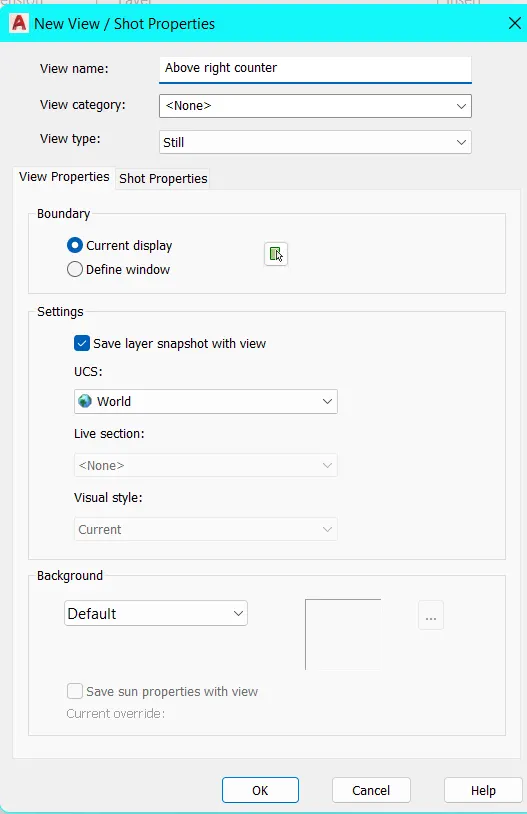
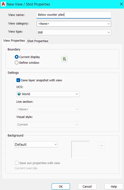
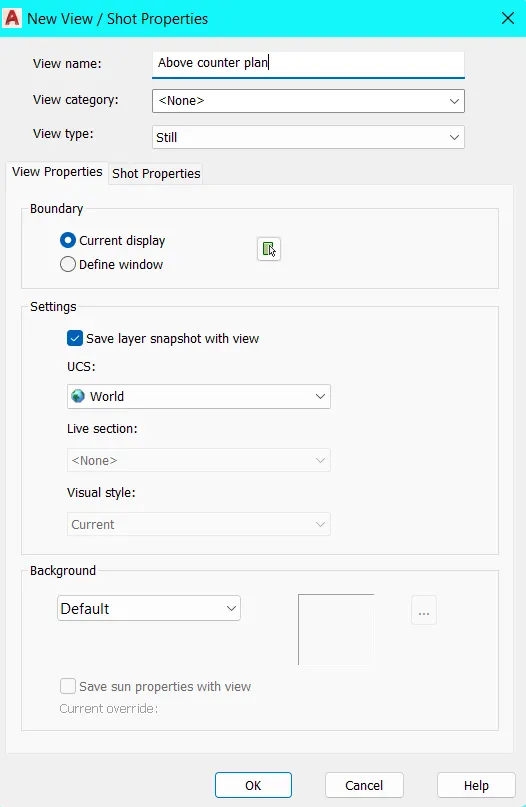
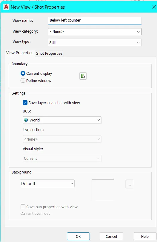
- Click on NEW VIEW
- A dialog box is opened
- Specify View Name as Above Right Counter
- Repeat similarly for other part of the drawing
- In the Model Viewports Tool
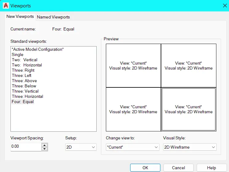
- Click to drop down Viewport Configuration and select FOUR: EQUAL
- Click on the NAMED, a dialog box open as VIEWPORTS
- Go to New Viewports Tab and type new name as Kitchen Layout 1
- Enter Layout command
- Click on New option
- A model tab is added
- Right click on the new model tab to rename as Kitchen Layout
- Enter PAGESETUP command
- A dialog box shows of Page Setup Manager
- Click on Modify
- New dialog box shows of Page Setup
- Change Printer/Plotter name as AUTOCAD PDF (General Documentation).pc3
- Change page size as ISO A4 (297.00 X 210.00 MM)
- Click OK and click CLOSE
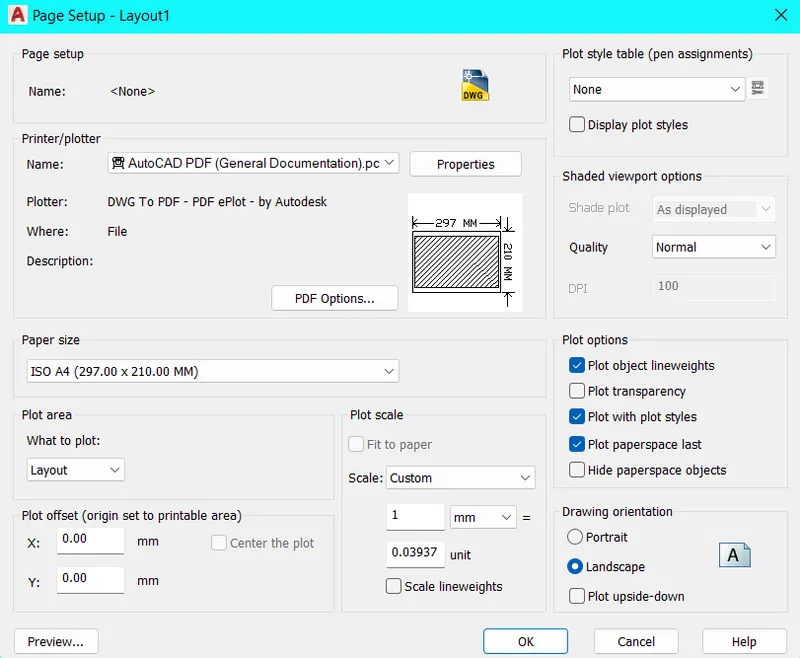
- Select to delete existing drawing in current page
- Set current layer as 0 from layer property
- From the Layout ribbon go to Layout Viewports Tool and click on the INSERT VIEW icon
- Click on the Above Right Counter and place in the sheet
- Similarly click on the other plan and place in sheet
- Resize the viewports as required
- Enter MS for Model Space or click model form the status bar
- Click the Plan and pan to adjust the viewport
- Simlarly for the other viewport
- After that Lock the viewports
- Click the Above Right Counter view port and go to layer property change the VP (View Port) colours for different member
- Similarly for the other Viewport
- Enter PS command for Page Layout
- Enter MT command for Multiline Text change text height then specify name
- Click on Plot icon or enter command Plot
- Ensure printer/plotter set as AUTOCAD PDF (General Documentation).pc3 click on OK
- Browse to file destination and save the PDF file
RESULT:
To follow the above procedure and obtained the final result
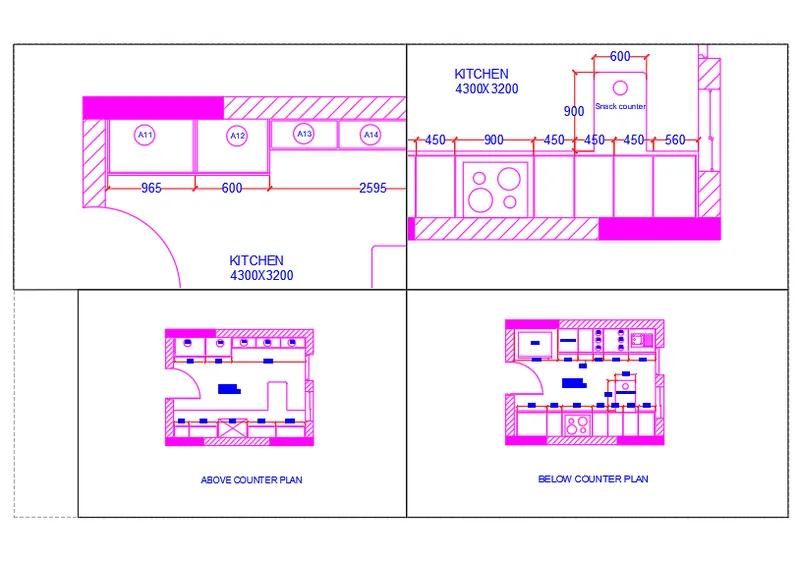
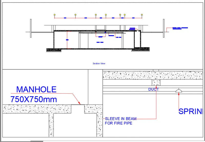
AIM: To create Kitchen layout of the challenge 9 as shown in the figure
INTRODUCTION: The Kitchen layout is created in AutoCAD. The paper size taken A4 and plot to save the PDF. Procedures explained with the diagram and the final result is given
PROCEDURE:
- Open week 10 challenge in AutoCAD
- Zoom the Section which is cover entire screen
- From VIEW ribbon
- In the NAMED VIEWS tool
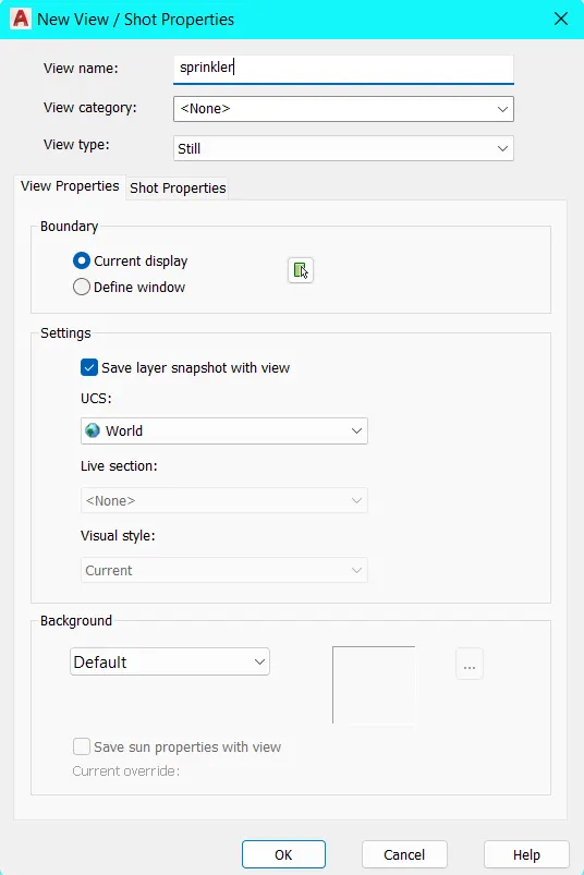
- Click on NEW VIEW
- A dialog box is opened
- Specify View Name as section
- Repeat similarly for other part of the drawing
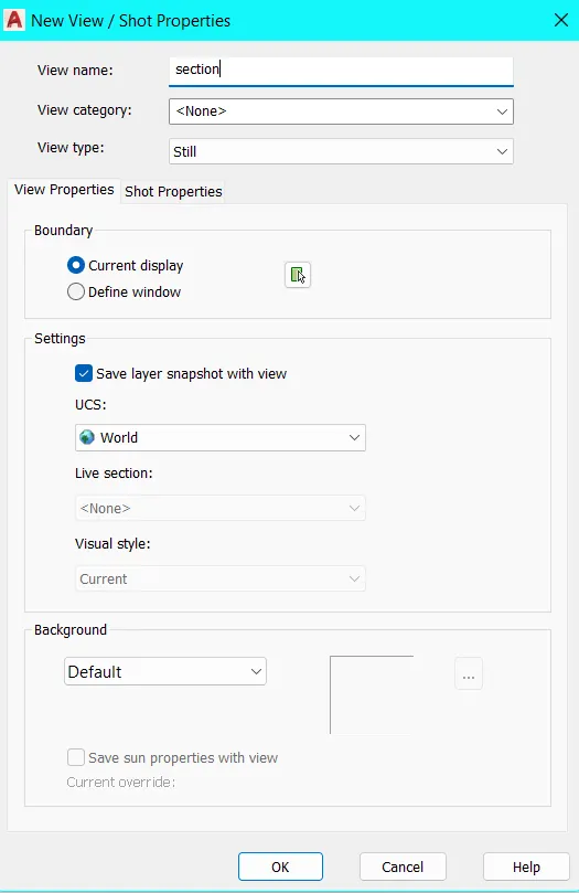
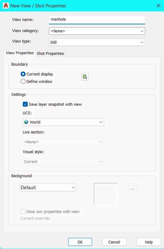
- In the Model Viewports Tool
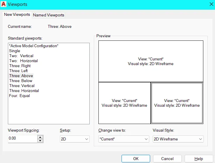
- Click to drop down Viewport Configuration and select THREE: ABOVE
- Click on the NAMED, a dialog box open as VIEWPORTS
- Go to New Viewports Tab and type new name as Section Layout
- Enter Layout command
- Click on New option
- A model tab is added
- Right click on the new model tab to rename as Section Layout
- Enter PAGESETUP command
- A dialog box shows of Page Setup Manager
- Click on Modify
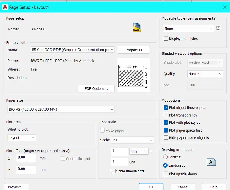
- New dialog box shows of Page Setup
- Change Printer/Plotter name as AUTOCAD PDF (General Documentation).pc3
- Change page size as ISO A3 (420.00 X 297.00 MM)
- Click OK and click CLOSE
- Select to delete existing drawing in current page
- Set current layer as 0 from layer property
- From the Layout ribbon go to Layout Viewports Tool and click on the INSERT VIEW icon
- Click on the Section and place in the sheet
- Similarly click on the Manhole and Sprinkle and place in sheet
- Click on section viewport, Unlock the viewport from status bar and change scale as 1:100
- Click on Manhole viewport, Unlock the viewport from status bar and change scale as 1:30
- Similarly for the Sprinkler viewport change the scale as 1:30
- Enter MS for Model Space or click model form the status bar
- Click the section and pan to adjust the viewport
- Simlarly for the other viewport
- After that Lock the viewports
- Click the Section view port and go to layer property change the VP (View Port) colours for different member
- Similarly for the other Viewport
- Enter PS command for Page Layout
- Enter MT command for Multiline Text change text height then specify name
- Click on Plot icon or enter command Plot
- Ensure printer/plotter set as AUTOCAD PDF (General Documentation).pc3 click on OK
- Browse to file destination and save the PDF file
RESULT:
To follow the above procedure and obtained the final result