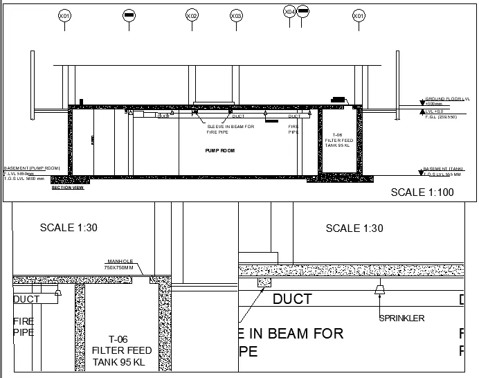
Creation of Multiple viewports, Scaling the drawing and setting in Template in AutoCad
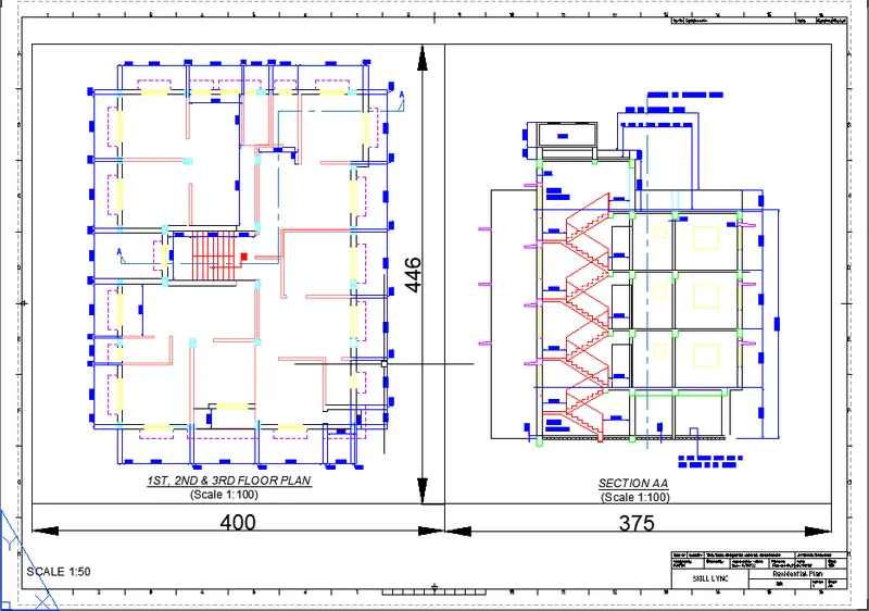
1. Create a layout of the Plan and Section A of the project in Challenges 7, using the template Tutorial-mArch.dwt in a scale as given in the Figure. Use the MV command to create the viewport of the size as shown in Figure. Also, use ATTEDIT command to edit the information in the title block. Use A1 size for the layout. Take a plot
AIM: To Create a layout of the Plan and Section A of the project in Challenges 7, using the template Tutorial-mArch.dwt in a scale as given in the Figure.
INTRODUCTION : Model View and Model space, Paper space and View Port options are used to Represent Created models into Requred scale to set the Drawing to a partiular pagesizes
To Cancel Selected Command Press “ESC”
To Invoke Previously Selected Command Press “ENTER”
PROCEDURE :
• Go to START MENU, select AutoCAD 2022.
• In the Command line type in: STARTUP [ENTER] • Enter new value of startup: 1
• Go to Application Menu and select "Challenge 7.dwg"
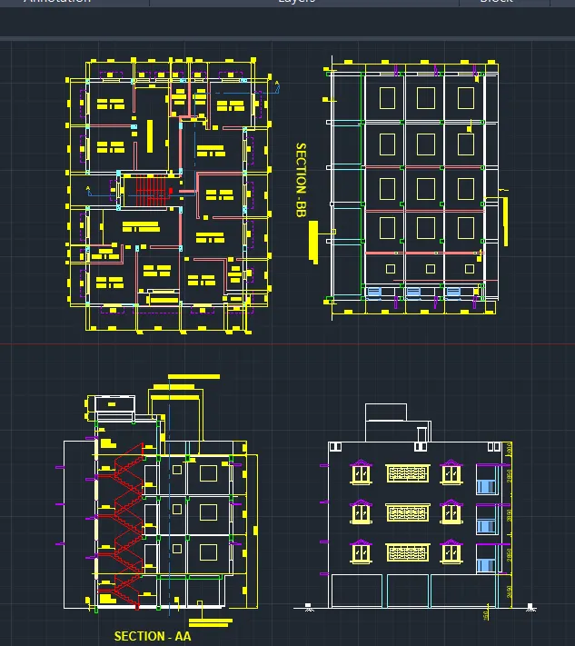
VIEW : go to View and Select a New View name the Vew specify view name as PLAN and Define boundary of the object by define boundary of the required object and press Enter
similarly Create the other multiple viewports such as section etc,. as per the Requirements
PLAN
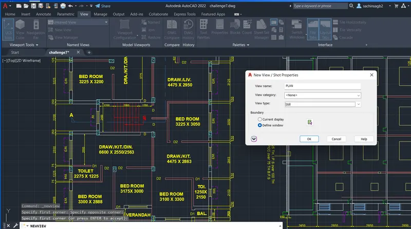
SECTION AA
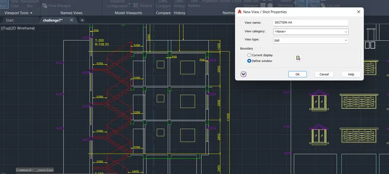
Viewport Configuration
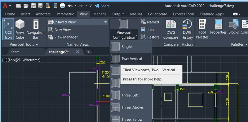
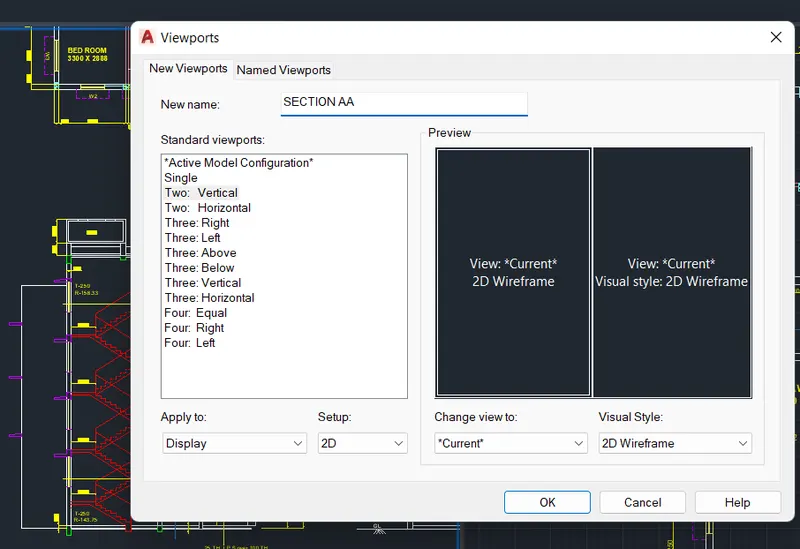
MV : type MV in command bar select Template by entering T
in the opened dialog box select " Tutorial-mArch.dwt "
select ISO A1
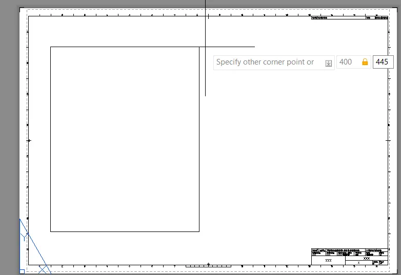
RECTANGLE : Specify the Rectangle dimension as 400, 445
similarly repeat and specify another dimension as 375, 445
MV : 'model view' Select the Named View in View port and place it
MS : 'model space' adjust the Viewport as per the Required Scale
PS: 'paper space' adjust and resize the Polygon if required
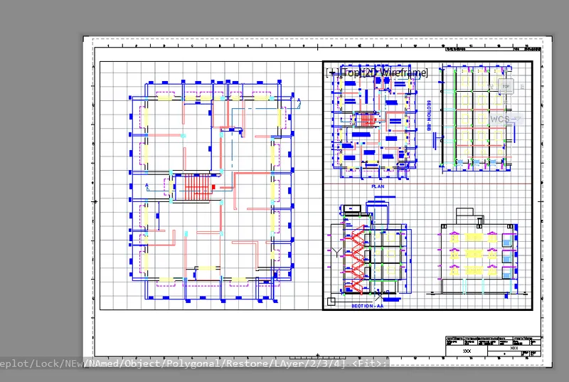
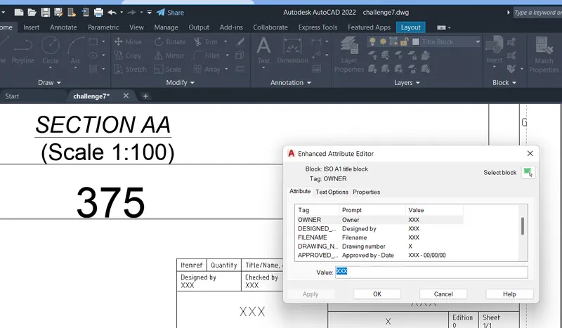
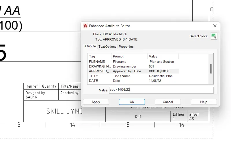
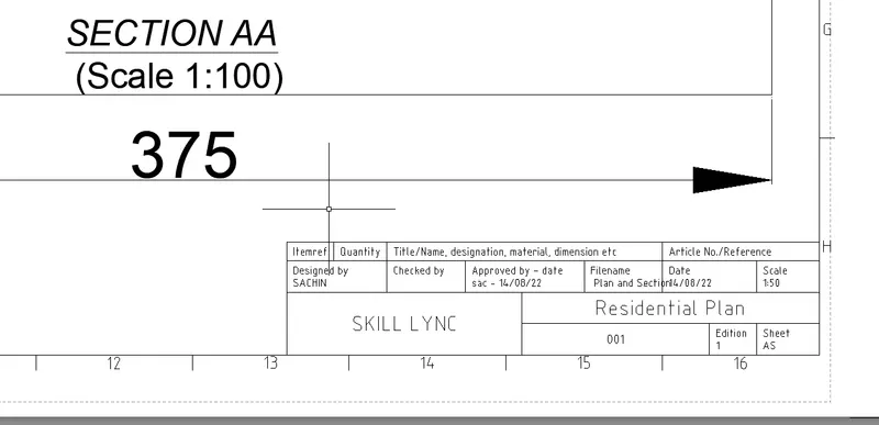
ATTEDIT : Select type and edit the Required desired credentials
DIMLENIAR: Select and Place the Desired Dimensions, Represent all the Dimensions
DIMSTY: Set Arrow size 25, Text Height 15, Precision to 0
DIMCONTINUE: Create Remaining Dimensions
MTEXT: Create a Text Box and Enter the sample text, Copy and Paste multiple in Desired Position and desired angle with Desired Size
EDIT TEXT (ED): Edit the MTEXT Created and Pasted and Type the actual name, size, rotation angle
RESULT :
2.Create a layout of the Kitchen drawn in Challenge 9 as shown in Figure. Use the scale as shown in the Figure. Use A4 Size page for the layout. Take a plot
AIM: To Create a layout of the Plan and Section A of the project in Kitchen Layout in Challenges 9, using the A4 Size scale as given in the Figure.
INTRODUCTION : Model View and Model space, Paper space and View Port options are used to Represent Created models into Requred scale to set the Drawing to a partiular pagesizes
To Cancel Selected Command Press “ESC”
To Invoke Previously Selected Command Press “ENTER”
PROCEDURE :
• Go to START MENU, select AutoCAD 2022.
• In the Command line type in: STARTUP [ENTER] • Enter new value of startup: 1
• Go to Application Menu and select "Kitchen layout.dwg"
VIEW : go to View and Select a New View name the Vew specify view name as Above Counter Plan and Define boundary of the object by define boundary of the required object and press Enter
similarly Create the other multiple viewports such as section etc,. as per the Requirements
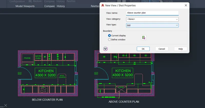
MV : type MV in command bar select Named view type Above counter plan, Below counter plan
select ISO A4
MV : 'model view' Select the Named View in View port and place it
MS : 'model space' adjust the Viewport as per the Required Scale
PS: 'paper space' adjust and resize the Polygon if required
MV : select MV command and create the polygon option and create the multiple view ports
use the Pan option to adjust the view by desired requirements
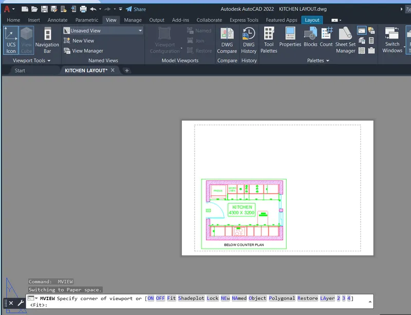
MTEXT: Create a Text Box and Enter the sample text, Copy and Paste multiple in Desired Position and desired angle with Desired Size
EDIT TEXT (ED): Edit the MTEXT Created and Pasted and Type the actual name, size, rotation angle
RESULT :
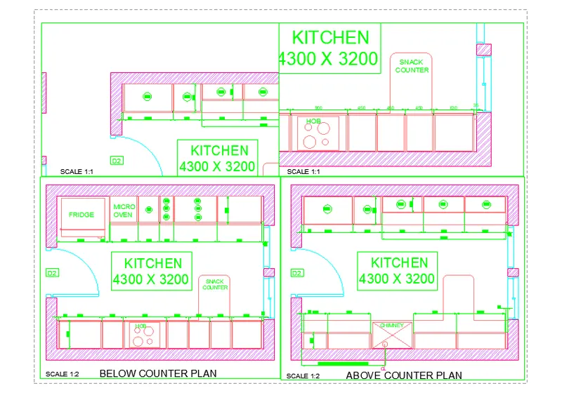
3. Create a layout of the section created in Challenges 9.
Use scale as mentioned in the Figure. Use MV command create multiple viewports. Take a plot.
AIM: To Create a layout of the Section of the industrial project from Challenges 9, using the A4 Size scale as given in the Figure.
INTRODUCTION : Model View and Model space, Paper space and View Port options are used to Represent Created models into Requred scale to set the Drawing to a partiular pagesizes
To Cancel Selected Command Press “ESC”
To Invoke Previously Selected Command Press “ENTER”
PROCEDURE :
• Go to START MENU, select AutoCAD 2022.
• In the Command line type in: STARTUP [ENTER] • Enter new value of startup: 1
• Go to Application Menu and select "Challenge 9.dwg"
VIEW : go to View and Select a New View name the Vew specify view name as Above Counter Plan and Define boundary of the object by define boundary of the required object and press Enter
similarly Create the other multiple viewports such as section etc,. as per the Requirements
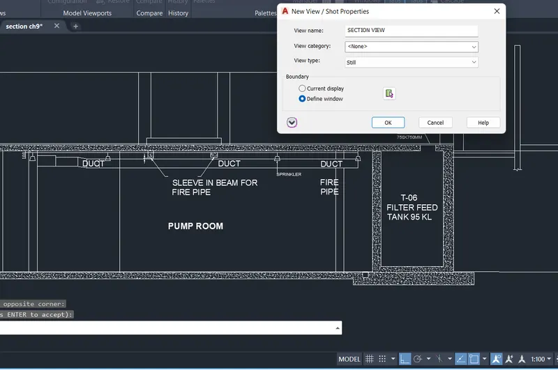
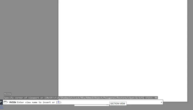
MV : type MV in command bar select Named view type Above counter plan, Below counter plan
select ISO A4
MV : 'model view' Select the Named View in View port and place it
MS : 'model space' adjust the Viewport as per the Required Scale
PS: 'paper space' adjust and resize the Polygon if required
MV : select MV command and create the polygon option and create the multiple view ports
use the Pan option to adjust the view by desired requirements
MTEXT: Create a Text Box and Enter the sample text, Copy and Paste multiple in Desired Position and desired angle with Desired Size
EDIT TEXT (ED): Edit the MTEXT Created and Pasted and Type the actual name, size, rotation angle
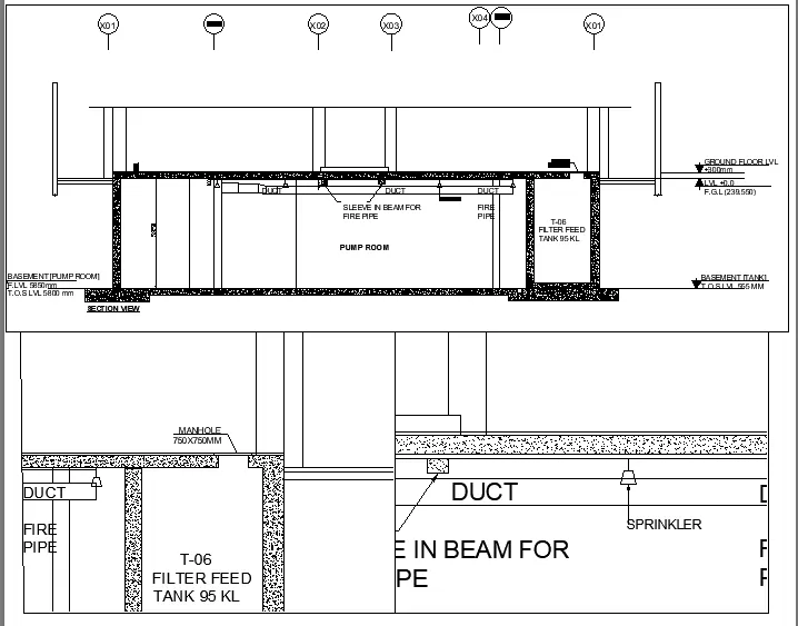
RESULT :