Creation of Multiple viewports, Scaling the drawing and setting in Template in AutoCad
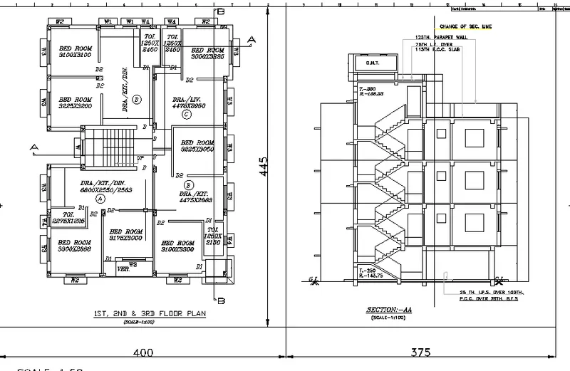
1. Create a layout of the Plan and Section A of the project in Challenges 7, using the template Tutorial-mArch.dwt in a scale as given in the Figure. Use the MV command to create the viewport of the size as shown in Figure. Also, use ATTEDIT command to edit the information in the title block. Use A1 size for the layout. Take a plot.
Ans1:
AIM: To create the layout of the pland and section AA of the building drawing created in Challenge 7 using th Tutorial-mArch.dwt and given scale. Using attribute editing to change the title block and plotting in A1 size.
PROCEDURE:
- Open a new drawing model and provide appropriated drawing settings, limits, zoom etc.
- Copy the drawings of building plan and section AA from challenge 7 drawing and paste in new drawing
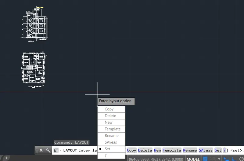
- Enter Layout command and use Template option to create a new layout.
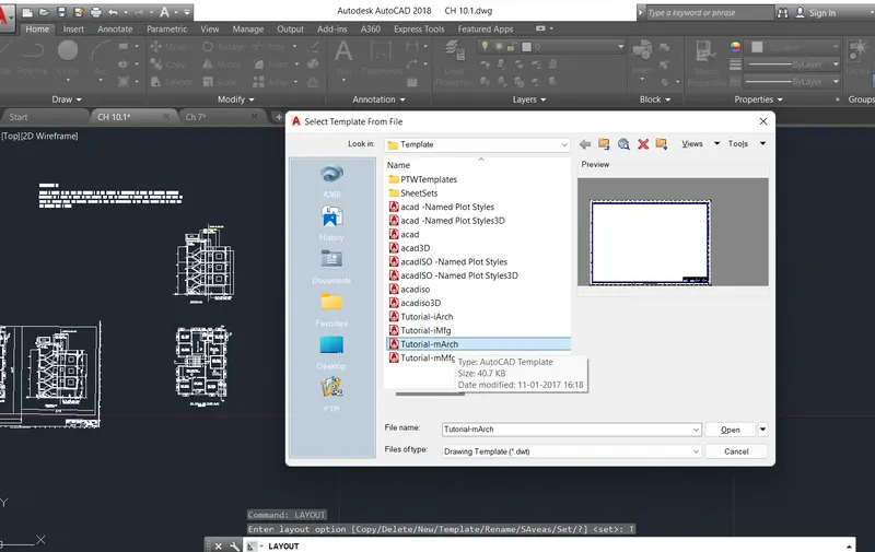
- Select the Tutorial-mArch template from the list of templates.
- With command MV create a viewport of size 400 x 445 as per given figure.
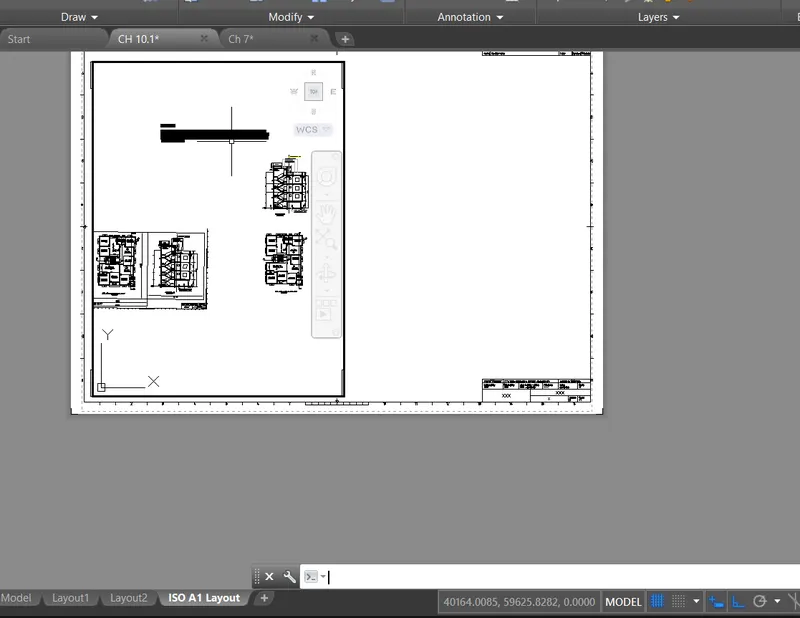
- Go to model space by MS command or double clicking inside the viewport.
- Zoom the drawing so as to fit the building plan inside the viewport.
- Zoom command with window selection can be used to properly fit the required drawing

- Create another viewport adjacent to the first one with size 375 x 445
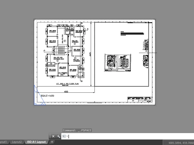
- Zoom the required section AA drawing in the second viewport
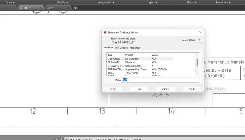
- Click on the title block and enter attribute editor command
- The list of the attributes assigned is popped out.
- Select each attribute and change the details of Value as required.
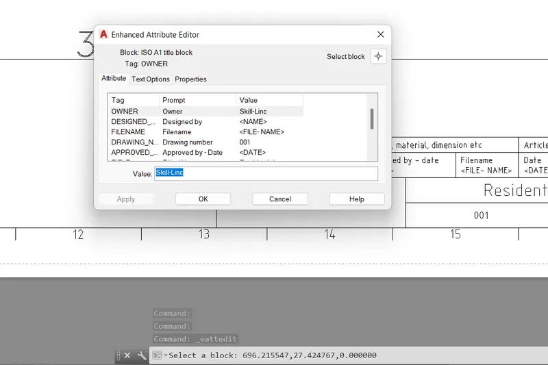
- Change the attribute value for Owner to Skill-Linc
- Similarly change the drawing number, drawing titel, filename etc.
- Thus the required title block is created as shown below
- Thus required layout is created along with the modified title block.
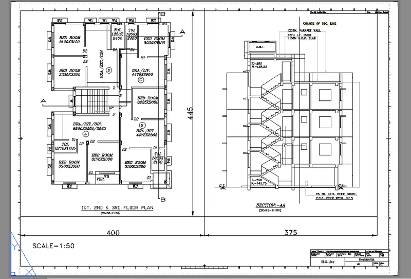
- Plot the drawing
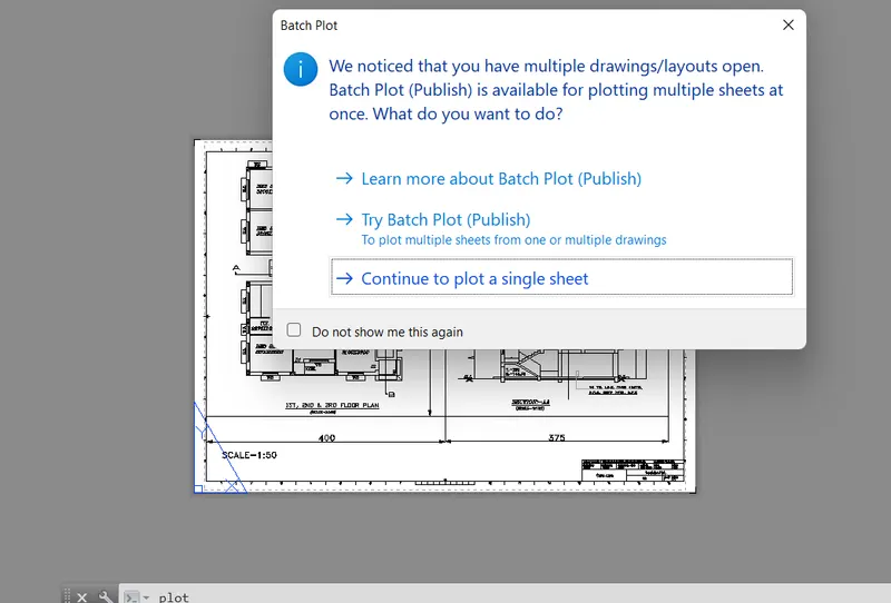
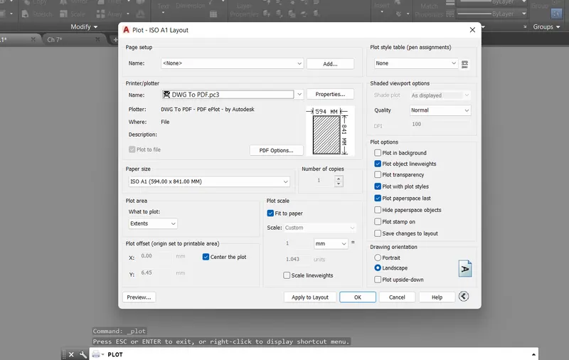
- Plot the drawing to PDF and select paper size to ISO A1.
- Fit to paper the drawing plot limits
- Apply to layout and press OK to plot.
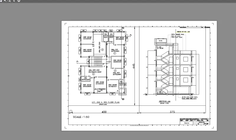
- The preview of the plot is as shown below
- Thus the following print out in PDF of ISO A1 size is ready as required.
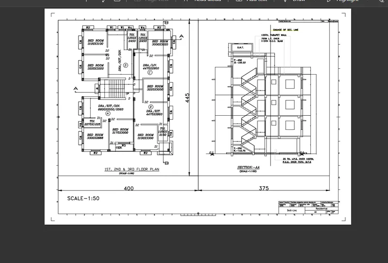
CONCLUSION: Thus we have created the layout for building plan and section AA drawings using 2 viewports, changed the attributes by editing the given title block and plotted the layout drawing in ISO A1 size.
2. Create a layout of the Kitchen drawn in Challenge 9 as shown in Figure. Use the scale as shown in the Figure. Use A4 Size page for the layout. Take a plot.
Ans 2:
AIM: To create a layout of the kitchen drawing from Challenge 9 by using viewports and scaling the drawing in layout viewport as given in the figure and plotting the layout in A4 size page.
PROCEDURE:
- Copy the kitchen layout drawings from the challenge 9 drawing and paste in the new drawing.
- Create a layout or use the layout1 in the drawing
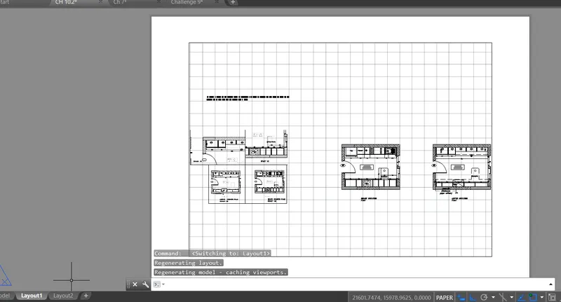
- Create viewports by MV command and use 4 viewports
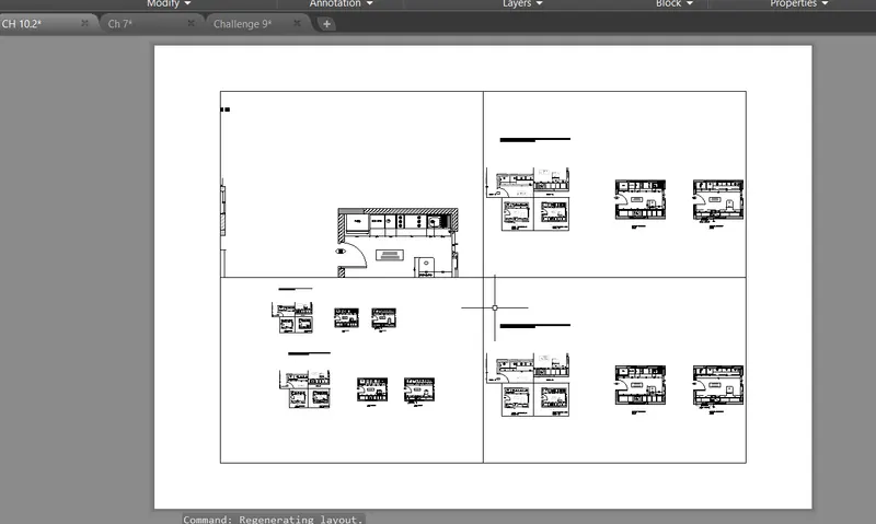
- Zoom the extent of the drawing by selecting window to be shown in the viewport 1
- Similarly zoom the other details in viewport2
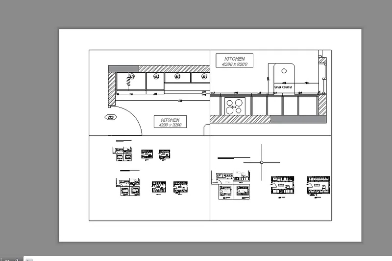
- Scale the details drawing viewport to 1:1 scale.
- Zoom the layouts in the lower 2 veiwports by selecting the window.
- Scale the layouts viewport to 1:2 scale.
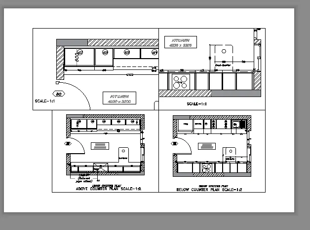
- Plot the drawing by selecting the A4 paper size
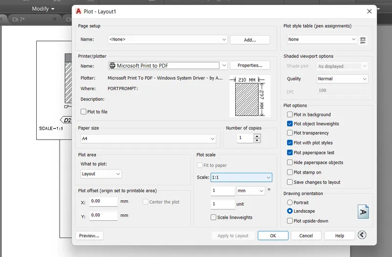
- Thus required drawing layout for kitche is ready as shown below.
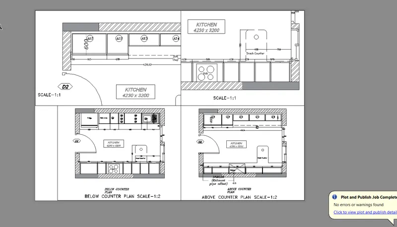
CONCLUSION: Thus we have created the layout for the kitchen layout plan and enlarged details as per the given figure, scaled the viewports as required and plotted the drawing on A4 size paper.
3. Create a layout of the section created in Challenges 9.
Use scale as mentioned in the Figure. Use MV command create multiple viewports. Take a plot.
Ans3:
AIM: To create layout of the section of Industrial building created in Challenge 9 using MV command for multiple viewports and plotting the layout.
PROCEDURE:
- Copy the section drawing from the challenge 9 and paste in the new drawing to create layout
- Open new layout or use the Layout 1 or 2 already in the drawing
- Create viewports using MV command.
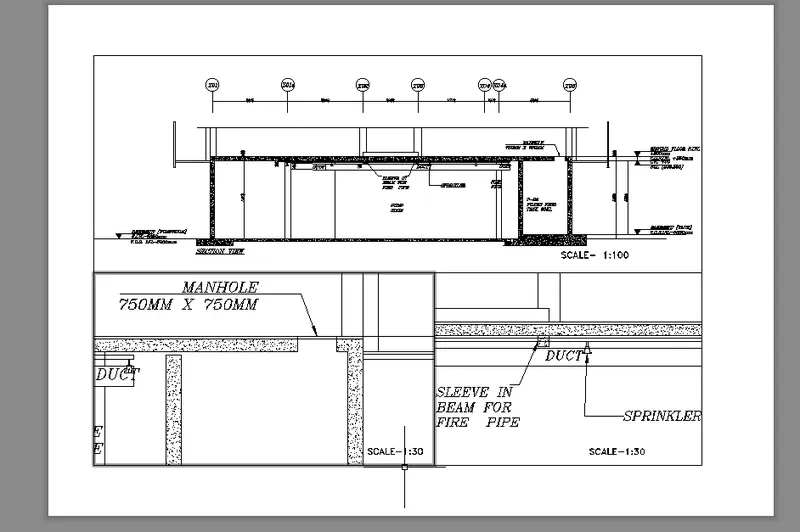
- Create 3 viewports and adjust the viewport size and positions as per given layout.
- Zoom the complete section drawing in the upper viewport by selecting the window
- Similarly select the window for the manhole details in one lower window
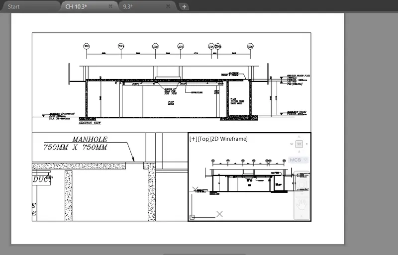
- Select the other section detail in the other lower viewport as per given figure
- Select the scale of viewports of details drawing to 1:30
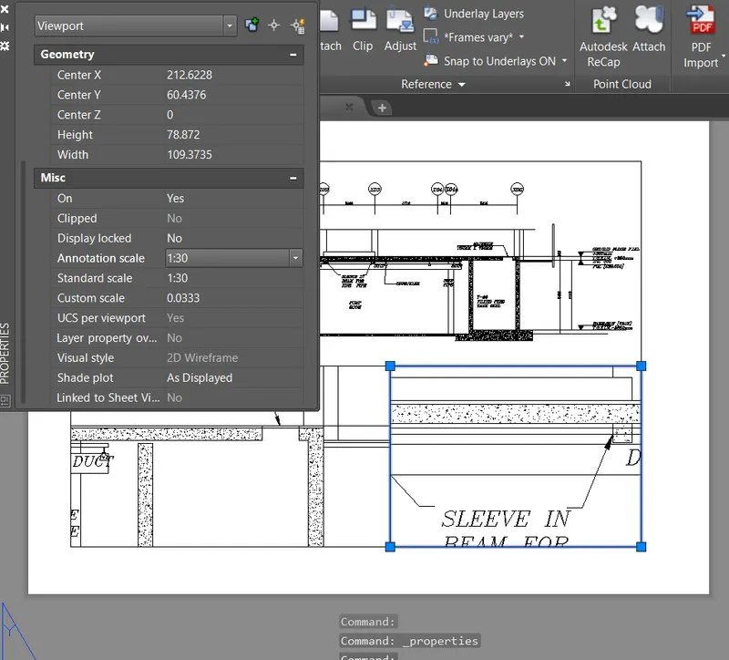
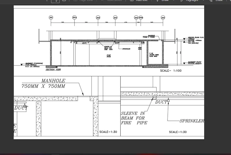
- Thus the required layout with section and detailed enlarged sections is created.
- Using the Mtext write down the scale of each viewport.
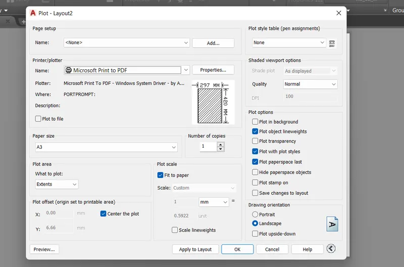
- Plot the layout to A3 size paper
- Thus the final layout drawing with multiple viewports is created and plotted in PDF as shown below
CONCLUSION: Thus we have created a layout for the section drawing from challenge 9 using MV command for multiple viewports and scaled the viewports as per given figure and plotted the layout drawing on A3 size page.