Creation of Multiple viewports, Scaling the drawing and setting in Template in AutoCad
Creation of Multiple viewports, Scaling the drawing and setting in Template in AutoCad
AIM:
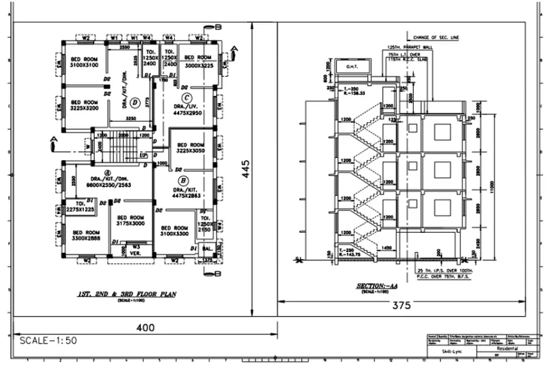
Create a layout of the Plan and Section A of the project in Challenges 7, using the template Tutorial mArch.dwt in a scale as given in the Figure. Use the MV command to create the viewport of the size as hown in Figure. Also, use ATTEDIT command to edit the information in the title block. Use Al size fothe layout. Take a plot
introduction: AutoCAD consists of a number of drawing and modification tools. Among the modification toolss are chamfer, fillet,offset,object snap, rotate,copy,move,mirror,trim, entend and join Chamfer: A chamfer is an angled line that meets the endpoints of two straight 2D objects its a sloped transition between two surfaces or adjacent faces on a 3D solid. We type CHA for this tool in command bar
drafting a following tools by using following commands like, by using object snap elliptical command, by using arcs commands construction lines and ray tools, divide and measure tool, and by Using modity commands like mirror, trim, entand explode, lenghten, align, break and join command, and manage layers in autoCAD 2019
PROCEDURE:
Open the challenge 7 plan & click on the layout. • Delete the current viewport displayed in the layout.
In the command box type layout,enter.
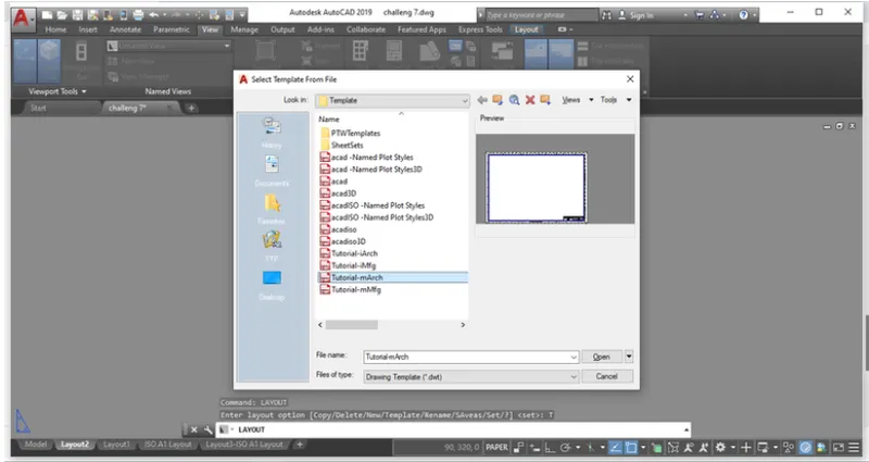
Lclick on the Templet, select the Tutorial-mArch,open,ISO
Al layout-ok,click on the ISO Al layout.
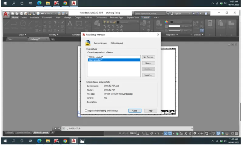
Rename it Plan & section.
• Click on the page setup manager.click on the modify.
Change the (Name,paper size Al,plot style Monochrome,scale-1:1),OK.
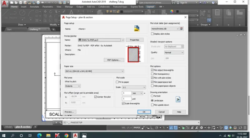
Type the commmand box "MV",enter.
create the tectange Size of 400X455 & 375X445 for
creating the viewport.
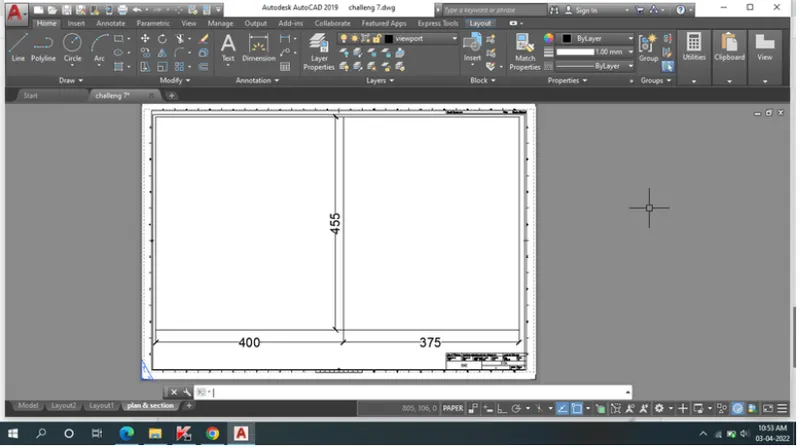
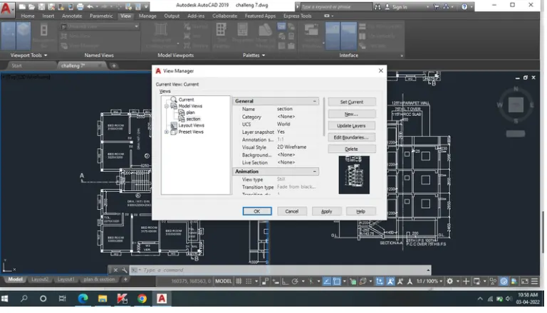
Open the model, click on the view, click on the view port
configuration,click on the Two:vertical.
In the First view zoom the plan & second view section.
type the view & new-create the name Plan & section
Click on the plan & section layout, type the "MV" select the object option & click on the rectangular then the drawing wii be displayed in the viewport. • Similarly do it for the second rectangle.
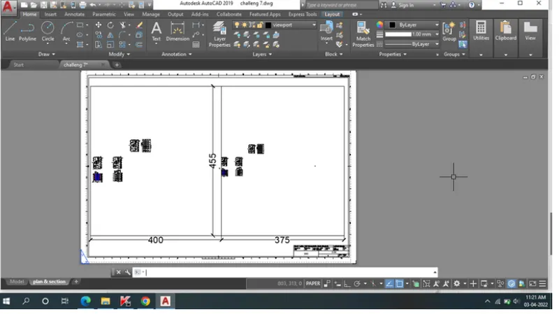
Command "MS" for model space & click on the viewport
we need to set the drawing. • Similarly do it on the second drawing on the view command.
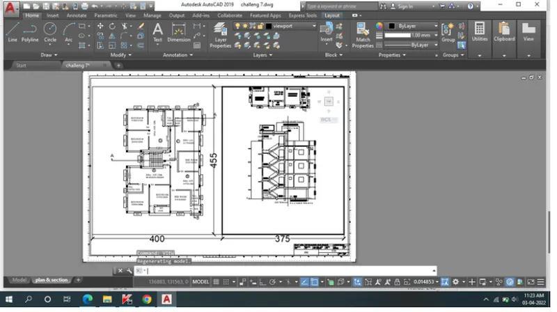
Command "MO"& type the "PS" in the command box.
select the first rectangle, click the scale as 1:50 & second rectangle also select the sameof 1:50.
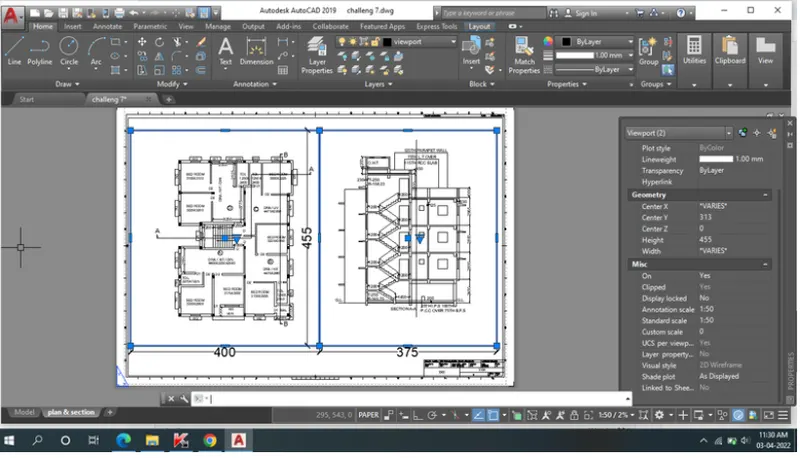
click on the dimension using dimension command.
click on the text using text command.
• Go to attributes in the template.
• Go to paper space & click on the template which is
block.
click on attributes & edit the attributes-double click the attribute text & dialogue box.
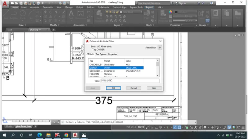
Taking a plot using Al sheet.
use the command "PLOT" the dilogue box.press the OK.
• Save the name & print will be tack.
Result:
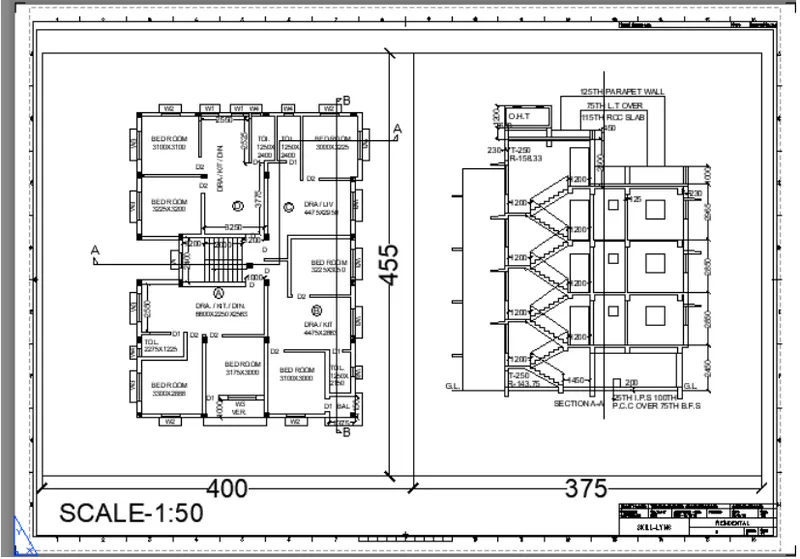
AIM:
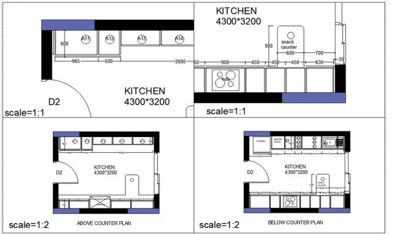
Create a layout of the Kitchen drawn in Challeng as shown in Figure. Use the scale as shown in the Figure. Use A4 Size page for the layout. Take a plot.
PROCEDURE:
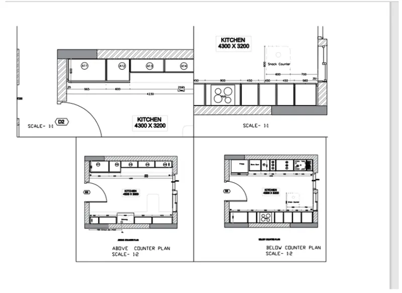
Open the challenge 9 plan & click on the layout.
Delete the current viewport displayed in the layout.
• Open the drawing & use command "VIEW" to create new views.
• The view manager dialogue box of new appears.click on model & click on new to create new view.
give the name as Kitchen, Kitchen2,Kitchen3,Kitchen4.

open the layout & chane the name as Kitchen.
• Click on the page setup manager.click on the modify.
Change the (Name=Dwd to pdf,paper size A4,plot style Monochrome,scale-1:30,click on scale lineweights),OK.
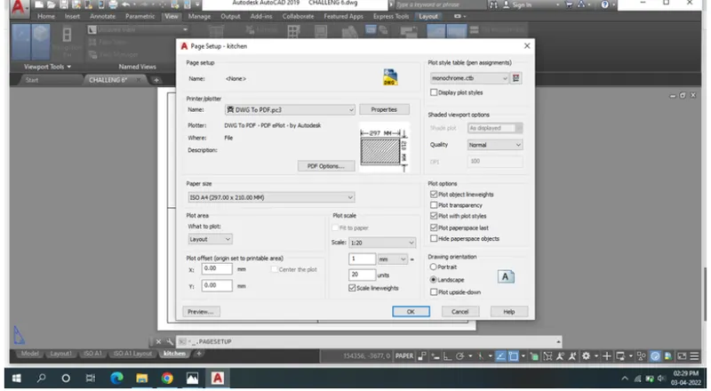
with "MV" command create 4 viewports by making the window.
select the firse rectangle & double click it, & insert the
view command.
• In the first rectangle select the kitchen 1,set current,apply,OK.
similarly do the same as remaining 3 rectangles.
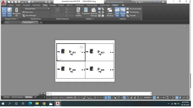
Type the "PS" command.
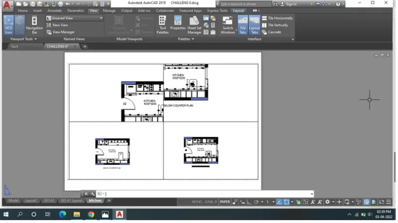
Command "MO"& type the "PS" in the command box.
select the first rectangle, click the scale as 1:1,second rectangle click the scale as 1:1,3rd rectangle click the scale as 1:2,& forth rectangle click the scale as 1:2.
Type pan & set the drawing.
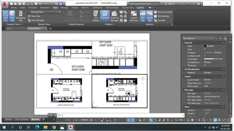
click on the text using text command,text height 150.
Now create the plot using plot command. • Select ok to convert to pdf.
Result:
AIM:
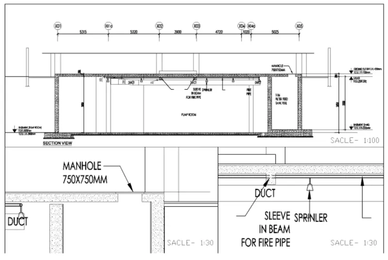
Create a layout of the section created in Challenges 9.Use scale as mentioned in the Figure. Use MV command create multiple viewports. Take a plot.
PROCEDURE:
Open the challenge 9 plan & click on the layout. • Delete the current viewport displayed in the layout.
• Rename the tab as industrial section.
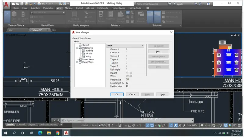
• Open the drawing & use command "VIEW" to create new
views.
• The view manager dialogue box of new appears.click on model & click on new to create 3 new view.
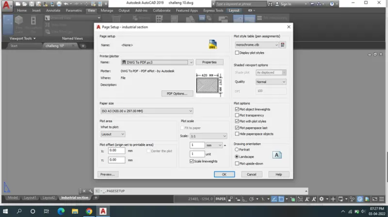
Click on the page setup manager.click on the modify. Change the (Name=Dwd to pdf paper size as ISO A3,plot style-Monochrome,scale-11,click on scale lineweights),OK
with "MV" command create 3 viewports by making the window.
select the firse rectangle & double click it, & insert the view command.
In the firsr rectangle select the section,set current,apply,OK.
• similarly do the same as remaining 2 rectangles.
• Type the "PS" command.
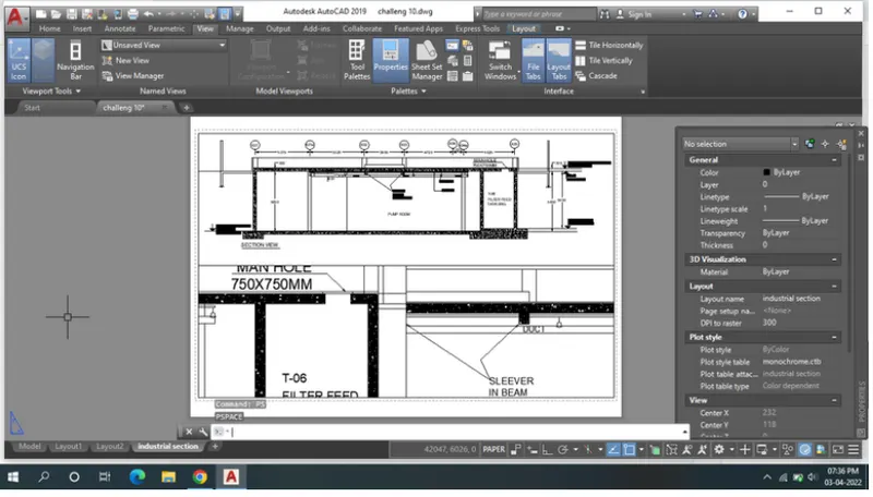
Command "MO"& type the "PS" in the command box.
select the first rectangle, click the scale as 1:100,second rectangle click the scale as 1:30,3rd rectangle click the scale as 1:30.
Type pan & set the drawing.
click on the text using text command,text height 150.
• Now create the plot using plot command.
• Select ok to convert to pdf.
RESULT:
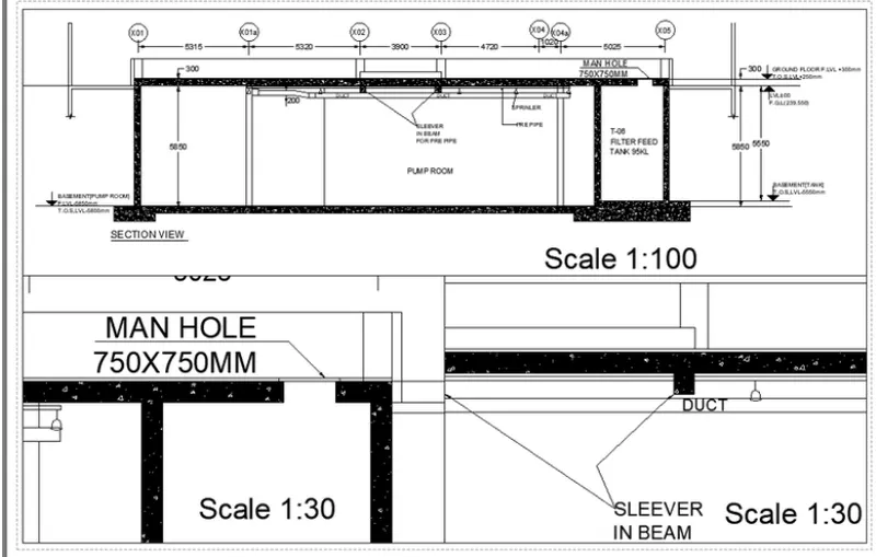
Conclusion:
ALL RESULT OF EACH DRAWING HAS BEEN ATTACHED WHICH WAS TAKEN FROM AUTOCAD