Creation of Multiple viewports, Scaling the drawing and setting in Template in AutoCad
Aim:
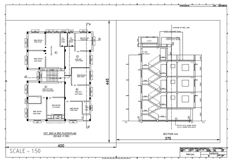
To Create a layout of the Plan and Section A of the project in Challenges 7, using the template Tutorial-mArch and set Drawing template in a scale as given in the Figure.
Introduction:
Create the layout of paln and section A by using the template Tutorial-mArch.dwt in scale of the plan as 1:50 and using multi viewport command to create the viewports, attributes edit command to edit the attributes. Use A1 paper size for the layout and take a plot of it.
Procedure:
- Open the Autocad software and open the file challege 7 as i saved in the name as week 7.dwg
- Create a new layout by using the 'Layout' command and name it as 'Plan & elevation'
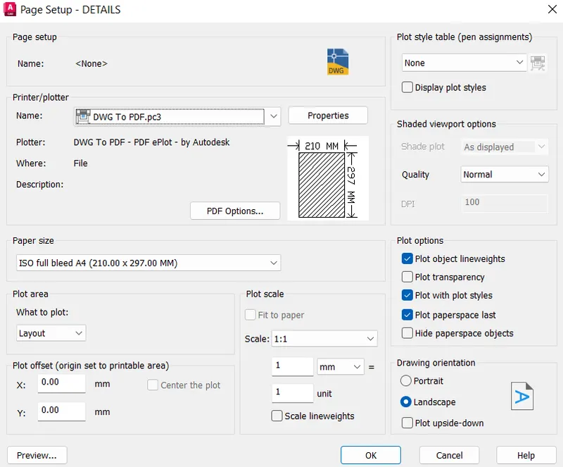
- Right click in the layout tab and open page setup manager.
- Set all the details as shown in the below figure.
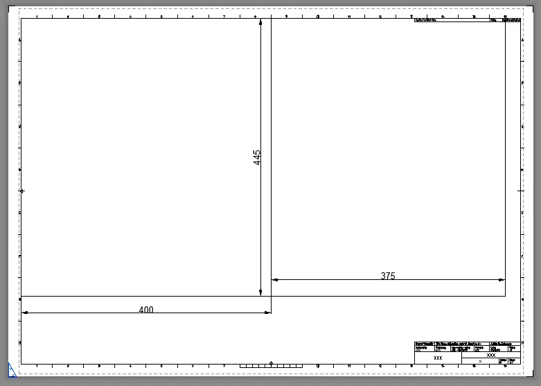
- Createa a rectangles of size 400mmX445mm and 375mmX445mm.
- USe 'MV' command and select object.
- Select the rectangles to make it viewports.
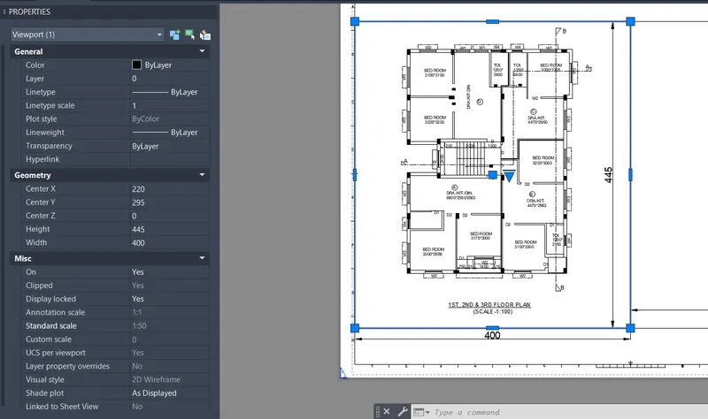
- Select the view ports and set the scale as 1:50
- Use pan tool to adjust the plan and elevation in the required position.
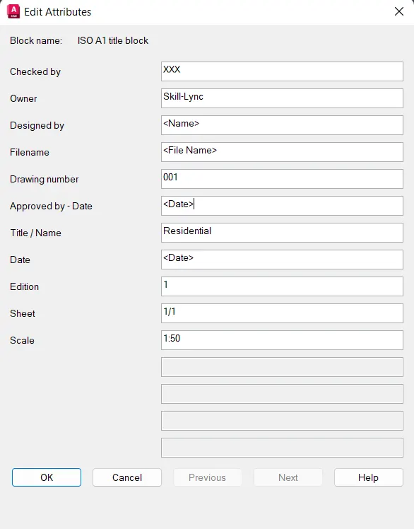
- Use attributes edit command, type 'ATT' in the command prompt.
- Edit the attributes in the layout.
- Fill the attributes details as shown in the below figure.
- Right click on the application icon.
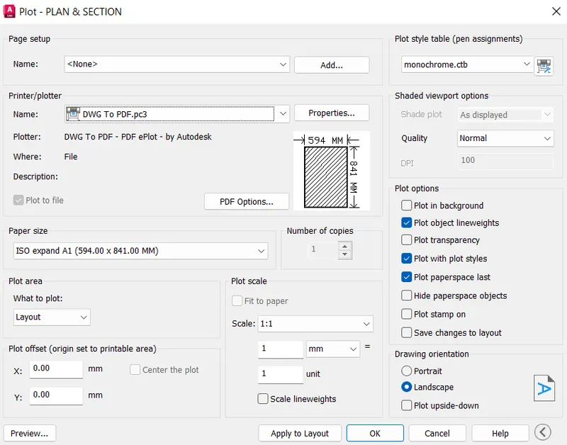
- Select the print option and select plot.
- Set the plot settings as shown in the below figure.
- Click the preview button to preview the plot.
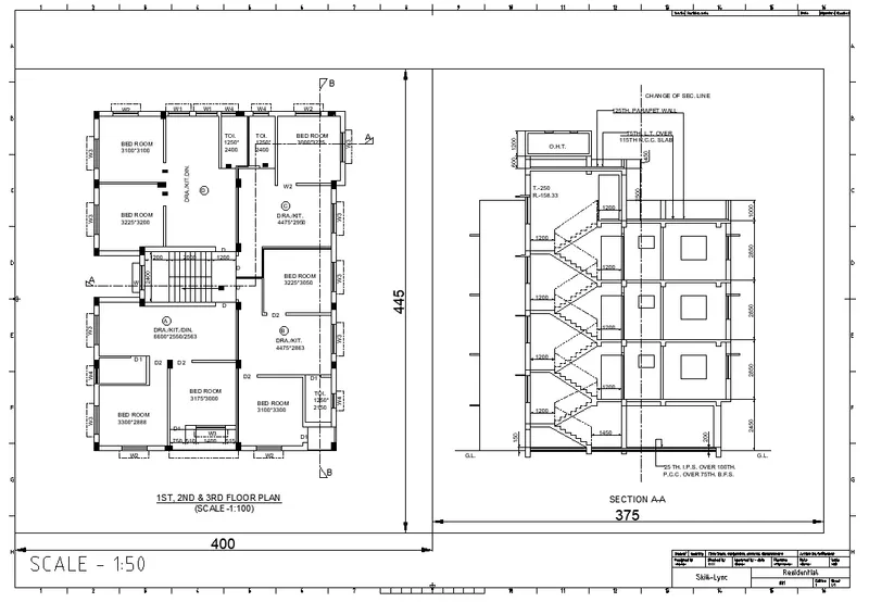
- Click ok to plot the layout.
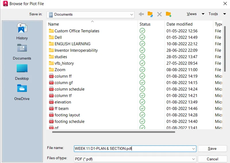
- Save the plot file as .pdf in the name of 'Week 11 d1 plan & elevation'
Result:
A layout of the Plan and Section A of the project in Challenges 7, using the template Tutorial-mArch is created and the drawing template in a scale as 1:50 is seted.
Aim:
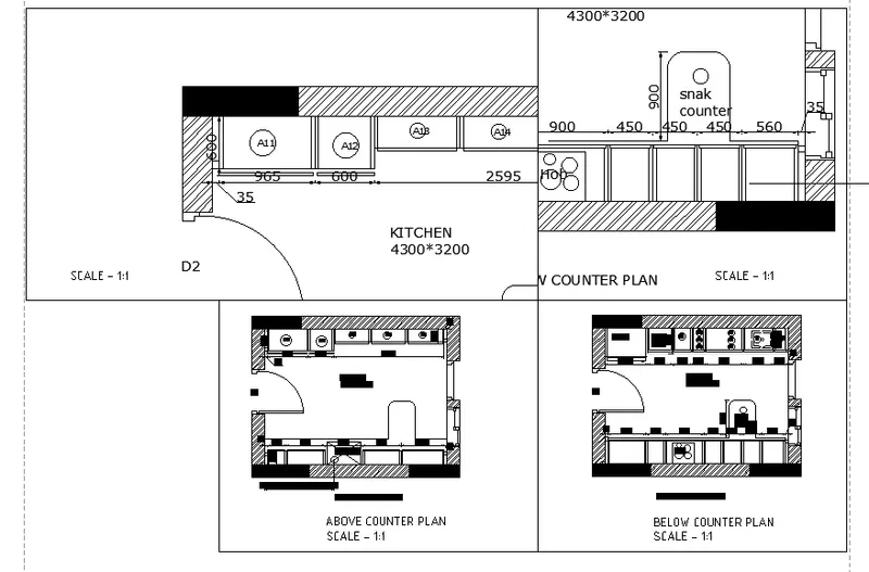
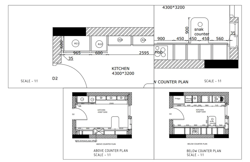
To create a layout of the Kitchen drawn in challenge 9 as shown in Figure and use the scale as shown in the Figure.
Introduction:
Create a layout of the kitchen drwan in challenge and use the scale as mentioned in the figure. Use A4 size paper to create a layout and make a plot of the layout.
Procedure:
- Open the Autocad software and open the file challege 7 as saved in the name as week 7 d3.dwg
- Create a new layout by using the 'Layout' command and name it as 'Detail'
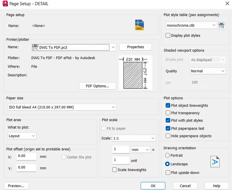
- Right click in the layout tab and open page setup manager.
- Set all the details as shown in the below figure.
- Use 'MV' command in the command prompt.
- Create multiple viewports as 4 numbers.
- Change the model space into paper space by using the 'PS' command in the command prompt.
- Select the first layout.
- Zoom the above counter plan part and set the scale to fit that part in the layout.
- Do the same process to the other layouts.
- Switch to the model space.
- Create the text of scale and plan by using 'MT' command in the command prompt.
- Right click on the application icon.
- Select the print option and select plot.
- Set the plot settings as shown in the below figure.
- Click the preview button to see the preview of the plot.
- Click ok to plot the layout.
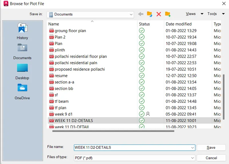
- Save the plot file as .pdf in the name of 'week 11 d2-Detail'
Result:
A layout of the Kitchen drawn in challenge 9 as shown in figure is created and scale is set as shown in the figure. Using A4 size paper the layout is created and plot is made.
Aim:
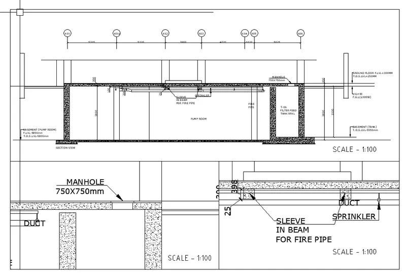
To create a layout of a section created in challenge 9 and Use scale as mentioned in the figure.
Introduction:
Create a layout of a section created in the challenge 9 and use scale as 1:100 for entire section and 1:30 for showing the details. Use MV command to create the multiple view ports and make a plot of the layout.
Procedure:
- Open the Autocad software and open the file challege 9 as saved in the name as week 9 d3.dwg
- Create a new layout by using the 'Layout' command and name it as 'Detail'
- Right click in the layout tab and open page setup manager.
- Set all the details as shown in the below figure.
- Use 'MV' command in the command prompt.
- Create multiple viewports as 3 numbers.
- Change the model space into paper space by using the 'PS' command in the command prompt.
- Select the first layout.
- Zoom the above counter plan part and set the scale to fit that part in the layout.
- Do the same process to the other layouts.
- Switch to the model space by typing 'MS' in the command prompt.
- Create the text of scale and plan by using 'MT' command in the command prompt.
- Right click on the application icon.
- Select the print option and select plot.
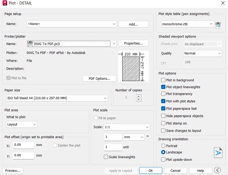
- Set the plot settings as shown in the below figure.
- Click the preview button to see the preview of the plot.
- Click ok to plot the layout.
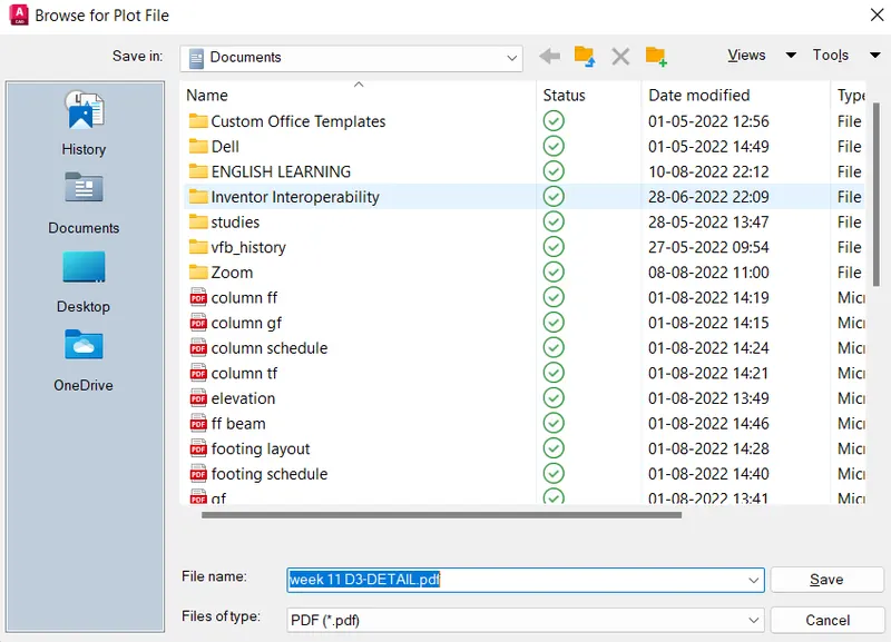
- Save the plot as .pdf file in the name of 'week 11 D3 Detail'
Result:
A layout of a section created in challenge 9 and Use scale as mentioned in the figure and plot is made.
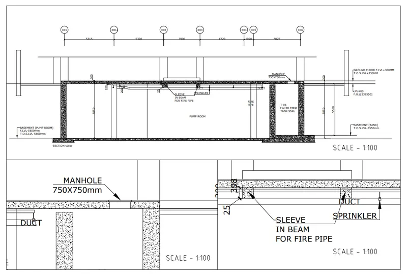
Note: The ploted pdf files are attached for the refererence.