Creation of Multiple viewports, Scaling the drawing and setting in Template in AutoCad
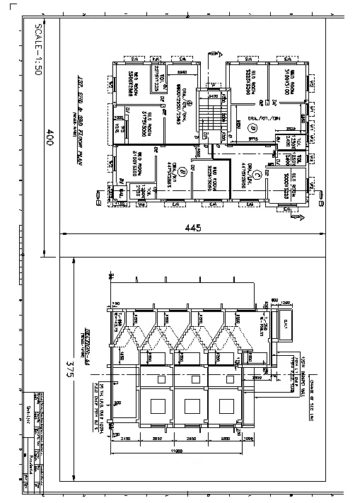
1. Create a layout of the Plan and Section A of the project in Challenges 7, using the template Tutorial-mArch.dwt in a scale as given in the Figure. Use the MV command to create the viewport of the size as shown in Figure. Also, use ATTEDIT command to edit the information in the title block. Use A1 size for the layout. Take a plot.
Aim:
To create a layout of the Plan and Section A of the project in Challenges 7 using the AutoCAD software
Introduction:
Create a layout of the Plan and Section A of the project in Challenges 7, using the template Tutorial-mArch.dwt in a scale as given in the Figure. Use the MV command to create the viewport of the size as shown in Figure. Also, use ATTEDIT command to edit the information in the title block. Use A1 size for the layout. Take a plot.
Procedure:
- First open the challenge 07 for draw the layout sheet
- And click Layout1
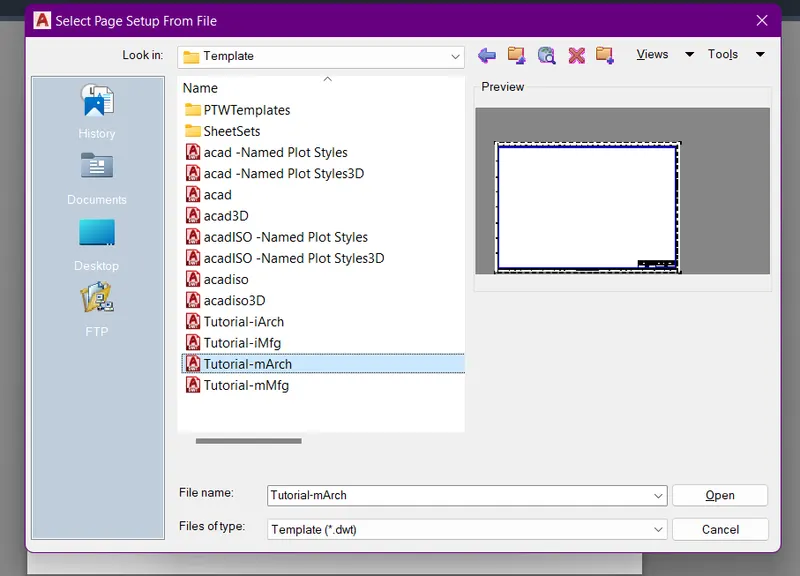
- Then, right click the Layout1 and then, click the select page setup from file
- And click the Files of type of Template(*.dwt) and then click the Tutorial-mArch template
- The dialogue box is as shown in below figure
- Then draw the View port as given in question
- And fix the drawing in that box
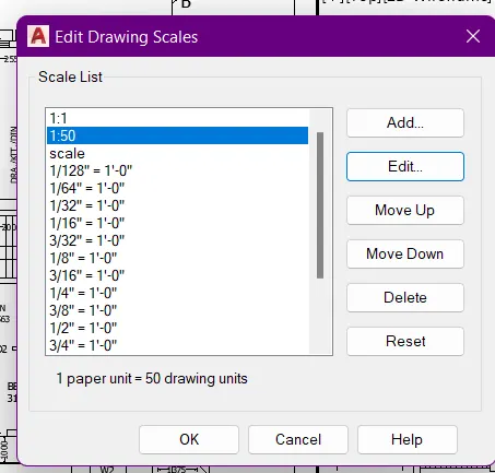
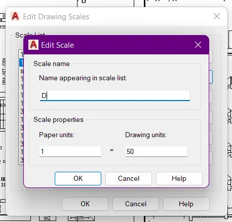
- Click the Scale and click the Add button
- Give a scale properties paper unit is 1 is equals to the drawing units is 50 in this drawing finally click OK
- Give Scale is 1:50
- Using the MV command for draw the rectangle as in the question
- The size of a view port is 400x445 and 375x445
- Then fix the drawing in the each port
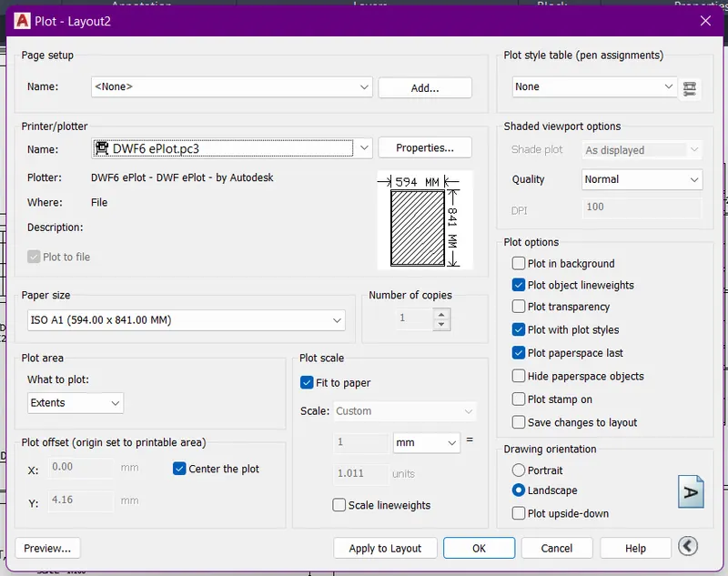
- Give the paper size is ISO A1(594.00 x 841.00 mm)
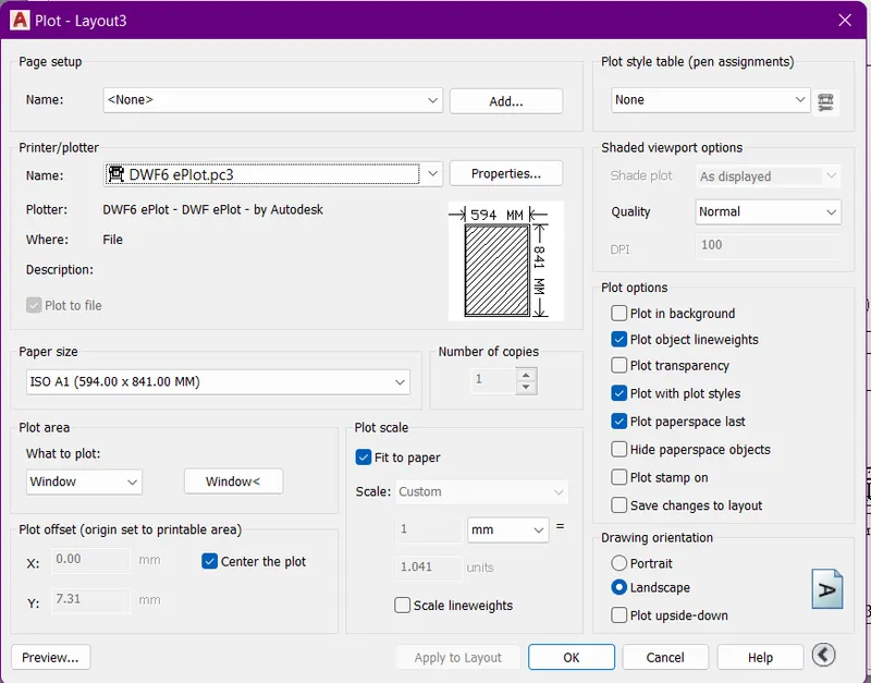
- Select the Landscape - click fit to paper and click center the plot
- Click the Apply to layout and click the OK button
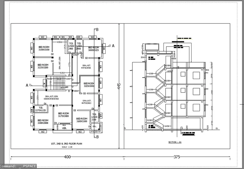
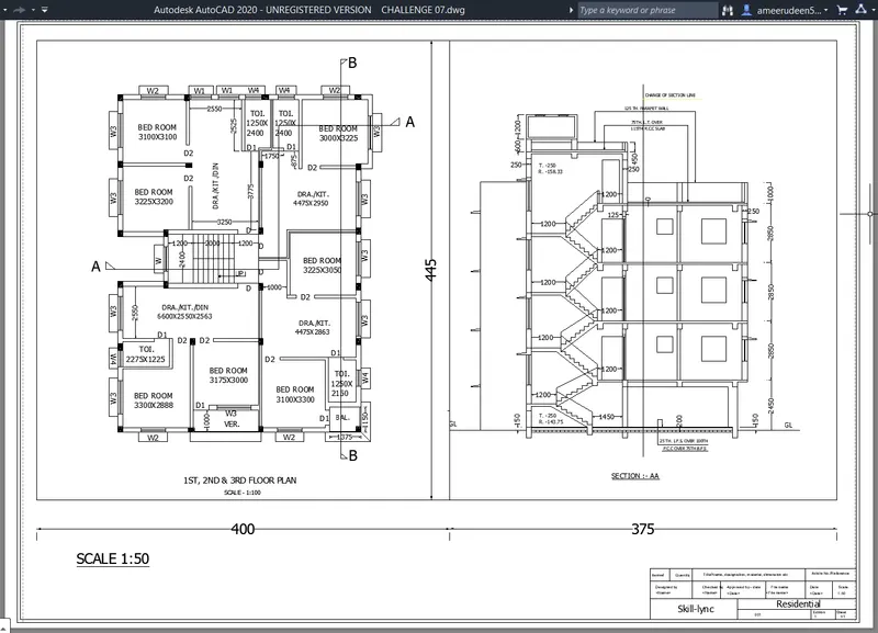
- The layout format is drawn using the rectangle and line command
- And using the MText command for five notes in the drawing sheet
- Then using the Dimlinear command for take the dimension of the view port
- Finish to take the layout of the drawing sheet as given in the question
- Take the screenshot of the all figures using the Snipping tool with the shortcut of Windows key+Shift+S
- Finally upload the figures for give an answer for this question
Result:
The creation of a layout of the Plan and Section A of the project in Challenges 7 is drawn using the AutoCAD software
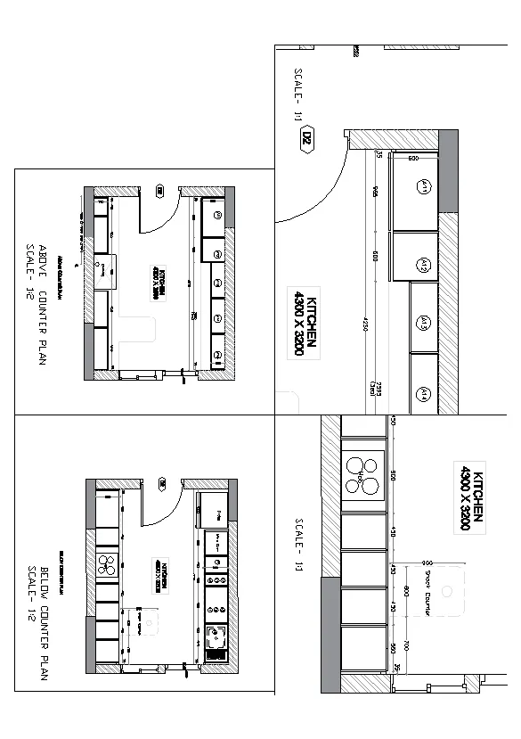
2. Create a layout of the Kitchen drawn in Challenge 9 as shown in Figure. Use the scale as shown in the Figure. Use A4 Size page for the layout. Take a plot.
Aim:
To create a layout of the Kitchen drawn in Challenge 9 as shown in Figure by using the AutoCAD software
Introduction:
Create a layout of the Kitchen drawn in Challenge 9 as shown in Figure. Use the scale as shown in the Figure. Use A4 Size page for the layout. Take a plot.
Procedure:
- Open the drawing challenge 09
- Click Layout1 for create a plot
- Next right click the Layout1 then click the page setup manager
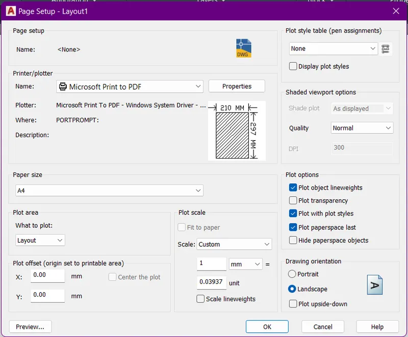
- Then click modify
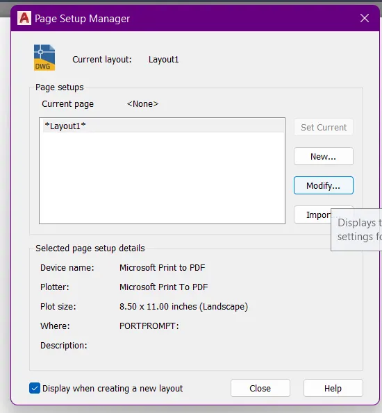
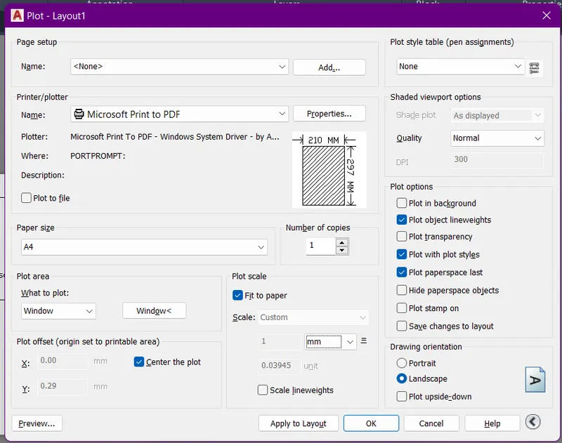
- Select the paper size is A4 as given in the question then click OK button
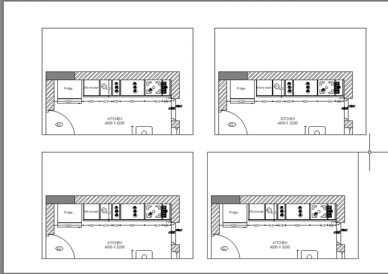
- Then, using MV command for create the multiple viewport for the drawing reference
- And zoom the drawing as given in the question
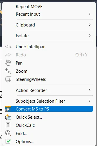
- Using the PS and MS command to modify the paper and view space for the drawing
- And then, give the scale for the drawing using the edit drawing scales
- The scale of the drawing is 1:1 and 1:2
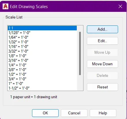
- By using the edit drawing scale for adding the scale of the drawing
- Then click Add button and give a name of 1:2
- And give a drawing units is 2 then click OK button
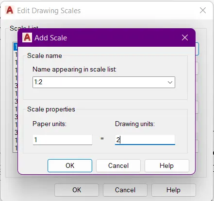
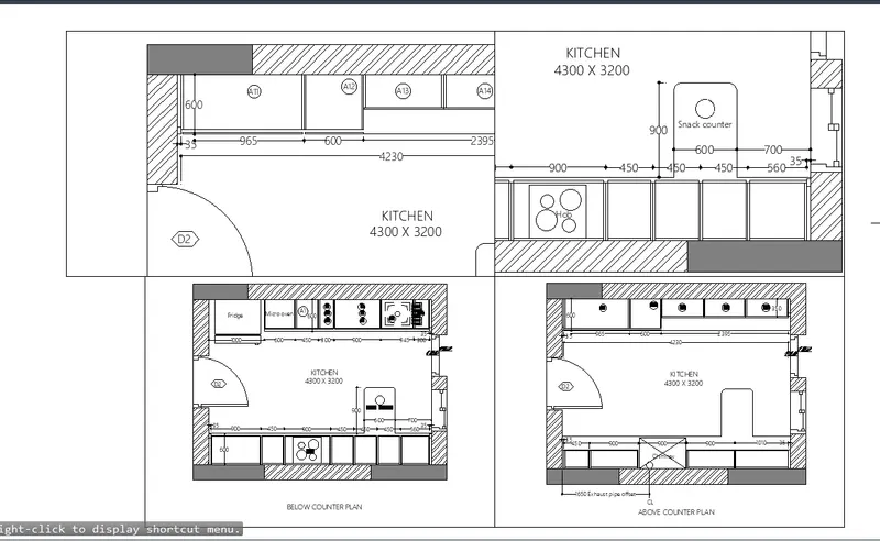
- Fix the drawing as in the question
- The below figure is shows the drawing sheet
- Here, using the MText command for give a text of the view port
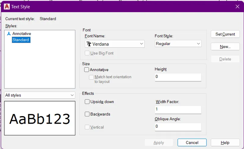
- The text font name is verdana and the height is 0.2
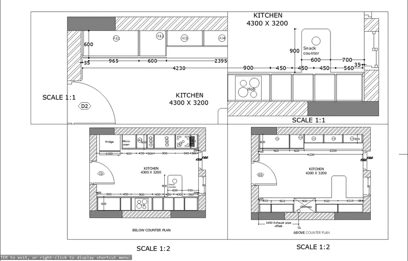
- Finally click to fit to paper and the center the plot for the appearence of the sheet
- Take the screenshot of the all figures using the Snipping tool with the shortcut of Windows key+Shift+S
- Finally upload the figures for give an answer for this question
Result:
The creation of a layout of the kitchen of the project in Challenges 9 is drawn using the AutoCAD software
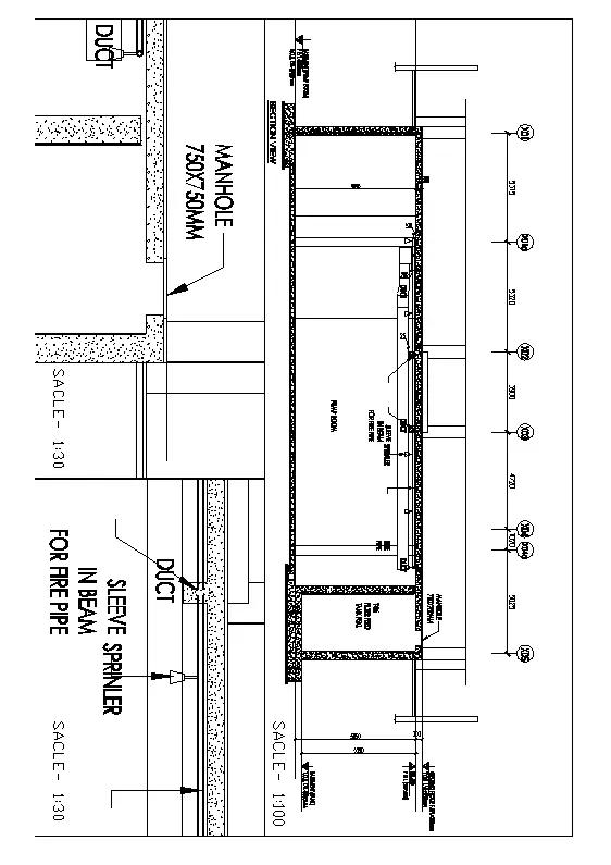
3. Create a layout of the section created in Challenges 9.
Use scale as mentioned in the Figure. Use MV command create multiple viewports. Take a plot.
Aim:
To create a layout of the section created in Challenges 9 using the AutoCAD software
Introduction:
Create a layout of the section created in Challenges 9.
Use scale as mentioned in the Figure. Use MV command create multiple viewports. Take a plot.
Procedure:
- First open the Layout3 in the challenge 09
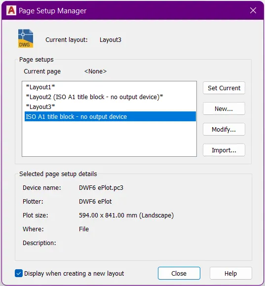
- And open the Page setup manager
- Then click ISO A1 title block and click setcurrent button and then click Close button
- And then, give the scale for the drawing using the edit drawing scales
- The scale of the drawing is 1:30 and 1:100
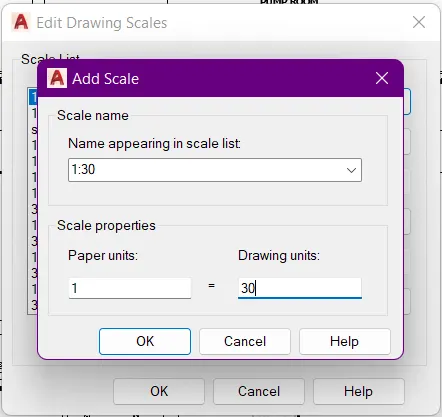
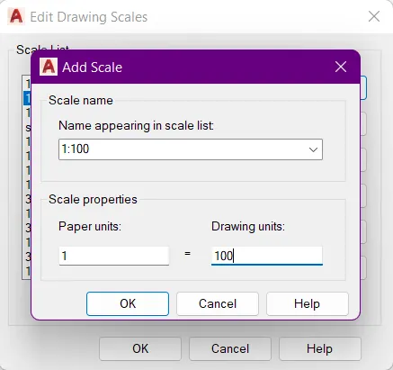
- By using the edit drawing scale for adding the scale of the drawing
- Then click Add button and give a name of 1:30 & 1:100
- And give a drawing units is 30 & 100 then click OK button
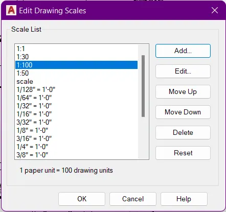
- Then, using MV command for create the multiple viewport for the drawing reference
- And adjust the drawing aas per the question
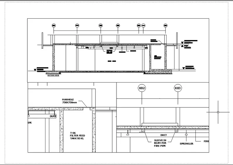
- Click the Scale of the sheet command and give a scale to the top view port 1:100
- And click the bottom two view ports and then give the scale of 1:30
- Finally using the MText command for give the scale name of the view port
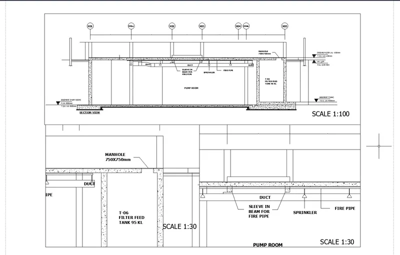
- Here, the Plot of the sheet is shows,
- Finally click to fit to paper and the center the plot for the appearence of the sheet
- Then click Apply layout and click OK button
- Take the screenshot of the all figures using the Snipping tool with the shortcut of Windows key+Shift+S
- Finally upload the figures for give an answer for this question
Result:
The creation of layout of the section drawing in challenge 09 is created by using the AutoCAD software successfully