Creation of Multiple viewports, Scaling the drawing and setting in Template in AutoCad
1.AIM
To Create a layout of the Plan and Section A of the project in Challenges 7 , creating viewports , editing attributed and taking a plot
COMMANDS USED
- Xref
- MV
- Layout
- Model space
- Paper space
- Rectangle
- Scale
- Mtext
- Dimlinear
- Pan
- Plot
INTRODUCTION
- A plan drawing is a drawing on a horizontal plane showing a view from above
- An elevation drawing is drawn on a vertical plane showing a vertical depiction
- A section drawing is also a vertical depiction , but one that cuts through space to show what lies within
- A layout is a 2D working environment for creating drawing sheets .The area within a layout is called paper space
PROCEDURE
STEP 1
- Open a new file
- Using xref command attach the drawing
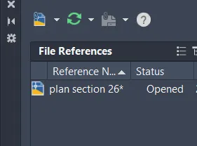
- After attaching Bind the attatched file and then explode the drawing file
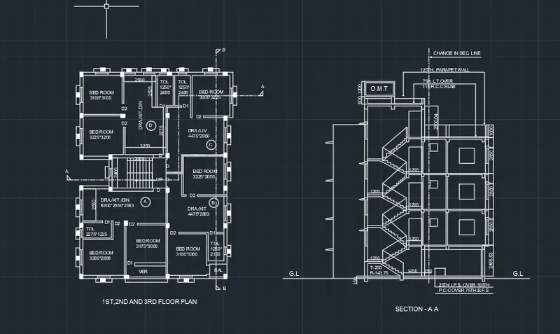
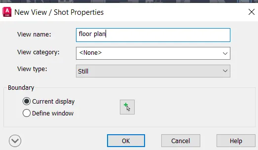
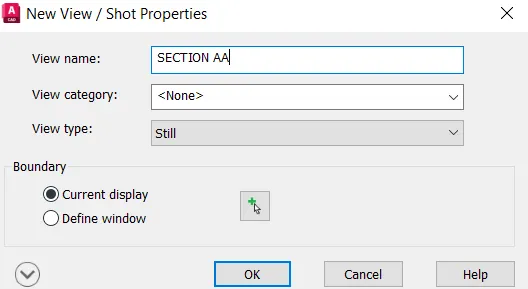
- From view select view manager and then select new
- Create two new view as floor plan and SECTION AA
STEP 2
LAYOUT
- Use the "LAYOUT" command and from that select templates ,from templates select mArch
- From the dialog box appeared select ISOA1 layout and rename it as "PLAN SECTION"
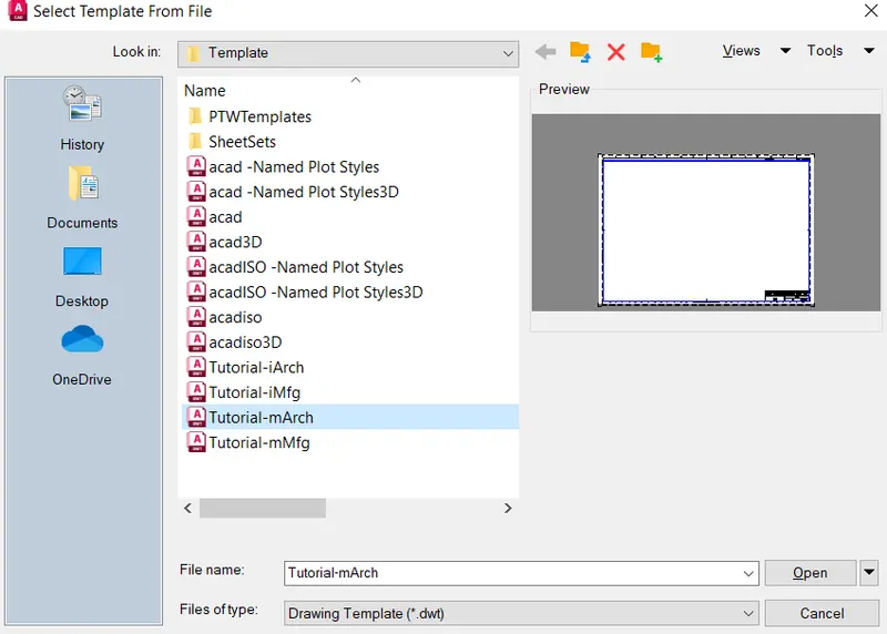
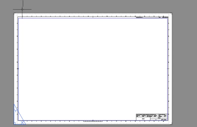
- Using MS command for the activation of model space .
- Inorder to create viewports
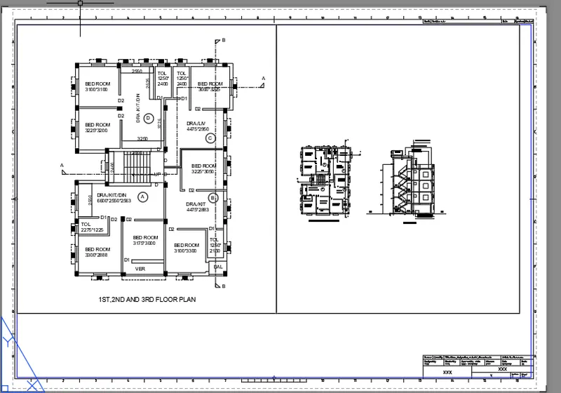
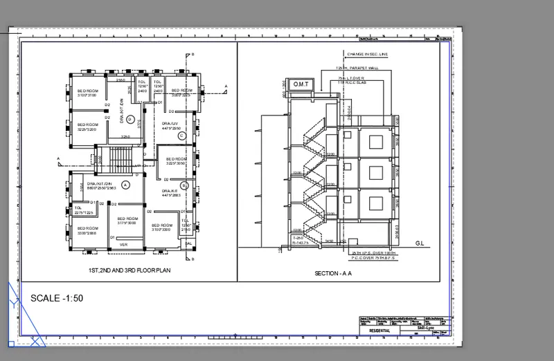
- Using rectangle command draw two rectangles of size 400*455 and 375*445
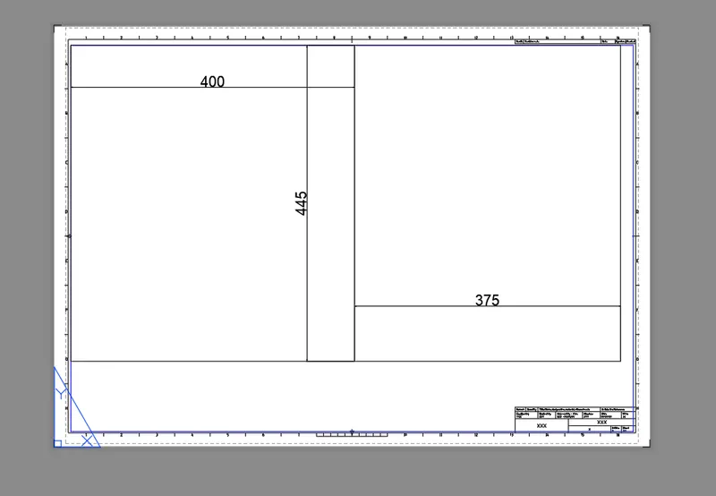
- Using the multiple view command "mv"
- We need to select the object option and select the rectangle
- Then the drawing will be displayed in the view port
- Same procedure is repeated in the second rectangle
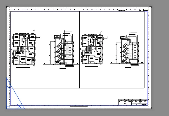
- Using the "MS" command for model space
- Click on the viewport in which we need to set the drawing
- Go to the view manager and then select floor plan and then set it as current then apply then ok
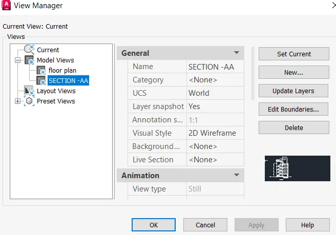
- Floor plan view will be displayed
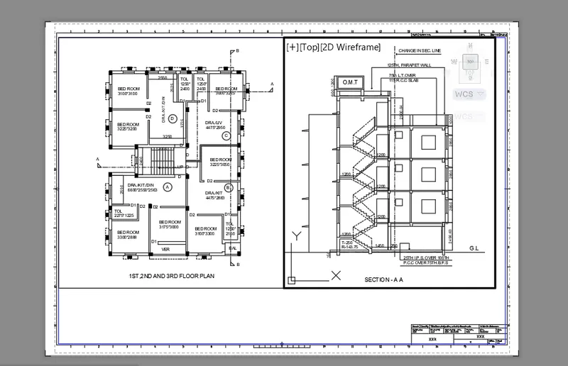
- Zoom in the drawing
- Give the scale as 1:50 and then lock the viewport so that the further zooming will not chamge the scale
- Similarly we can do this in the other viewport also
STEP 3
EDITING ATTRIBUTES AND TYPING TEXT
- For that first we need to go to paper space by "ps " Command
- Using mtext type scale -1:50 in the left corner of the sheet
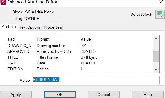
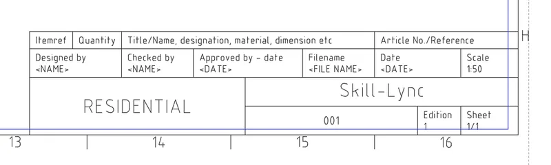
- Then by using the attribute edit command "ATTEDIT" we can edit the attribute
- Doulble click on the attribute that needed to be edited
- Now edit as per the requirement
STEP 4
PLOT
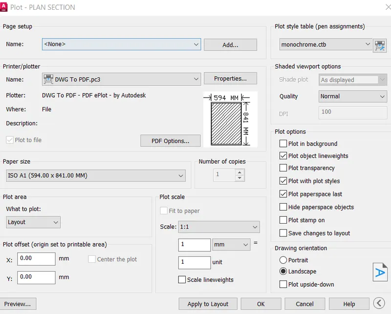
- Using the "PLOT" command plot dialog box is apperaed
- Give the name as DWG TO PDF and set the paper size as ISO A1
- Select what to plot as layout
- orientation is given as landscape and select the pen assignment as "Monochrome "
RESULT
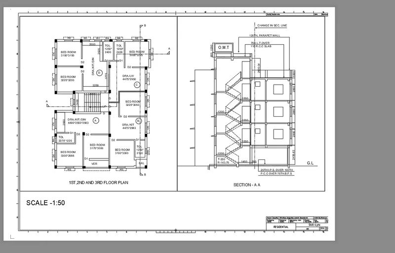
Layout is created using template ,view port is created using the MV command , attributes in the templates are edited and a plot is taken .
--------------------------------------------------------------------------------------------------------------------------------------------
2.AIM
To Create a layout of the Kitchen drawn in Challenge 9 in A4 sheet and take a plot
COMMANDS USED
- Xref
- MV
- Layout
- Model space
- Paper space
- Rectangle
- Scale
- Mtext
- Dimlinear
- Pan
- Plot
INTRODUCTION
- A plan drawing is a drawing on a horizontal plane showing a view from above
- An elevation drawing is drawn on a vertical plane showing a vertical depiction
- A section drawing is also a vertical depiction , but one that cuts through space to show what lies within
- A layout is a 2D working environment for creating drawing sheets .The area within a layout is called paper space
PROCEDURE
STEP 1
- Open a new file
- Using xref command attach the drawing
- After attaching Bind the attatched file and then explode the drawing file
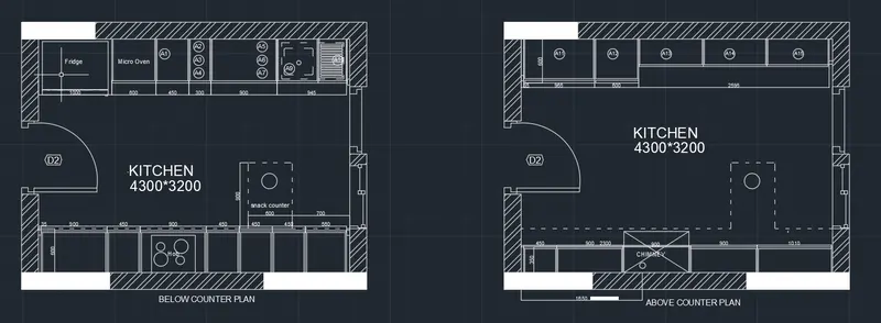
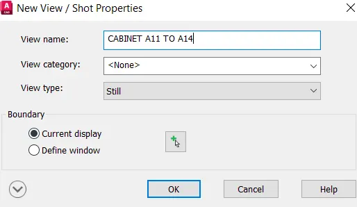
- From view select view manager and then select new
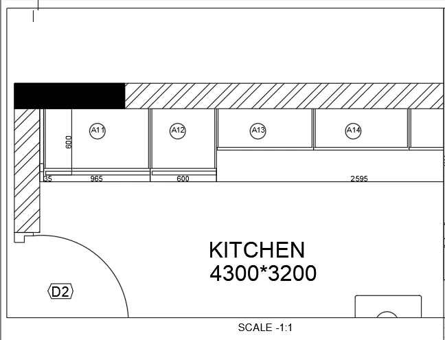
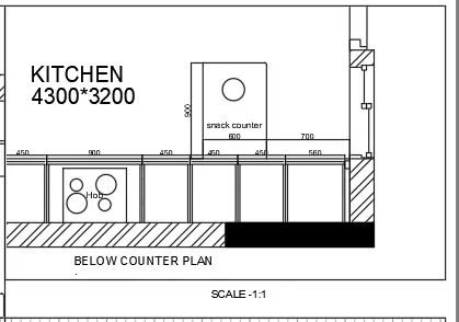
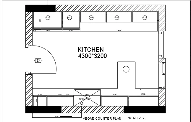
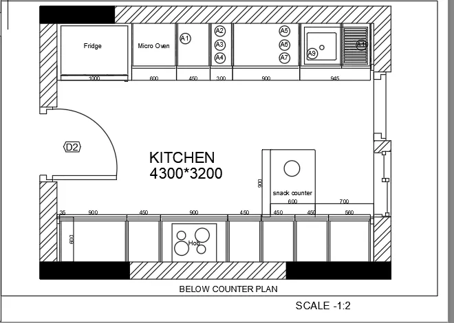
- Create two new view as ABOVE THE COUNTER PLAN , BELOW THE COUNTER PLAN , CABINET A11 TO A14 ,SNACK COUNTER
STEP 2
LAYOUT
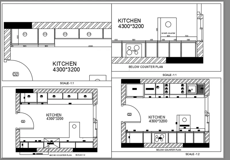
- Using the LAYOUT command create layout with four viewports
- Open the layout tab , rename the layout as kitchen layout
- Delete the existing viewport
- Default is the A4 sheet with "MV" command create 4 viewports by making the window
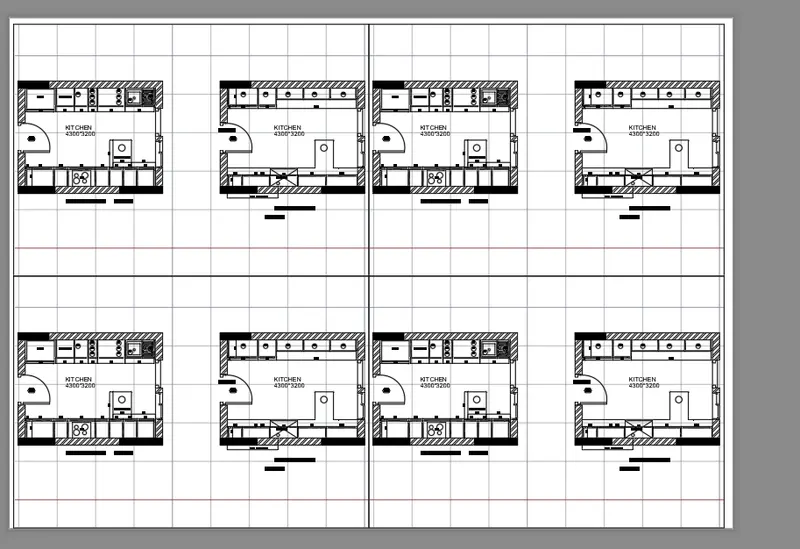
- Using the "MS" command for model space
- Click on the viewport in which we need to set the drawing
- Go to the view manager and then select SNACK COUNTERand then set it as current then apply then ok
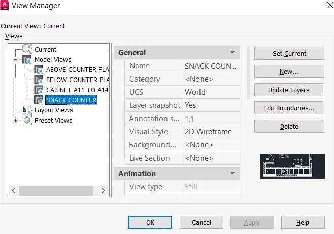
- SNACK COUNTER view will be displayed
- Zoom in the drawing
- Give the scale as 1:1 and then lock the viewport so that the further zooming will not change the scale
- Similarly we can do this in the other viewport also
STEP 3
PLOT
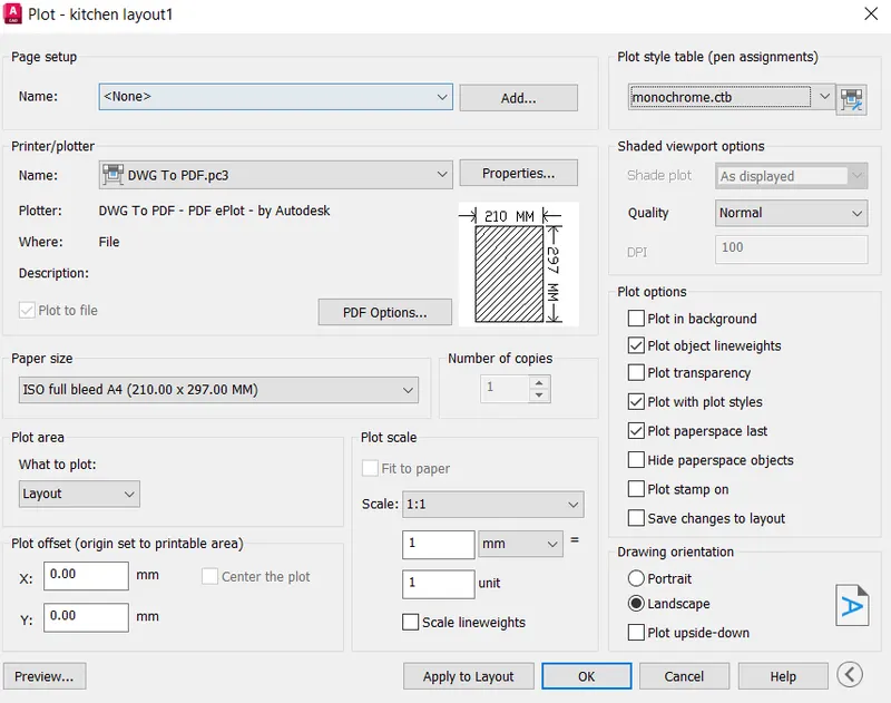
- Using the "PLOT" command plot dialog box is apperaed
- Give the name as DWG TO PDF and set the paper size as ISO A4
- Select what to plot as layout
- orientation is given as landscape and select the pen assignment as "Monochrome "
RESULT
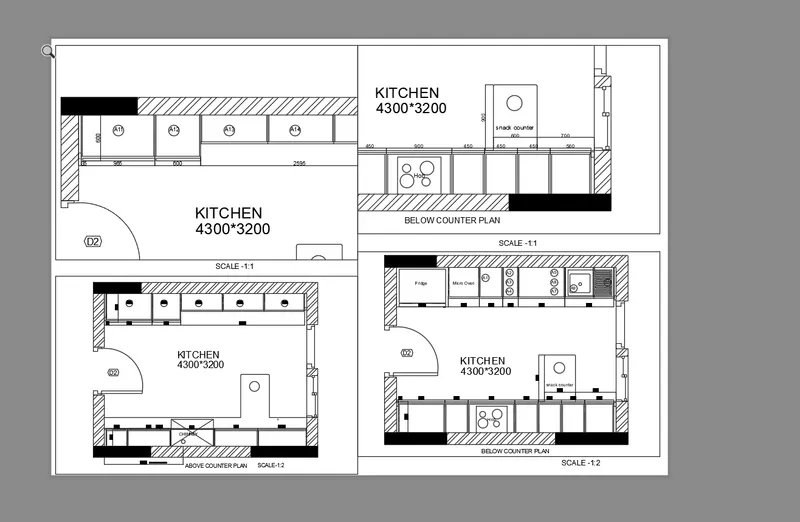
- Different views of kitchen layout is created
- Layout with four viewports with A4 Sheet is created
- Plot is created
-----------------------------------------------------------------------------------------------------------------------------------------
3.AIM
To Create a layout of the industrial building and take a plot
COMMANDS USED
- Xref
- MV
- Layout
- Model space
- Paper space
- Rectangle
- Scale
- Mtext
- Dimlinear
- Pan
- Plot
INTRODUCTION
- A plan drawing is a drawing on a horizontal plane showing a view from above
- An elevation drawing is drawn on a vertical plane showing a vertical depiction
- A section drawing is also a vertical depiction , but one that cuts through space to show what lies within
- A layout is a 2D working environment for creating drawing sheets .The area within a layout is called paper space
PROCEDURE
STEP 1
- Open a new file
- Using xref command attach the drawing
- After attaching Bind the attatched file and then explode the drawing file
- From view select view manager and then select new
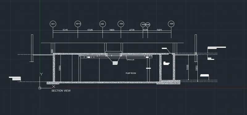
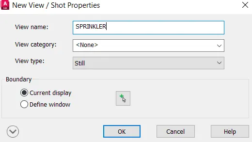
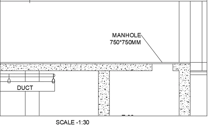
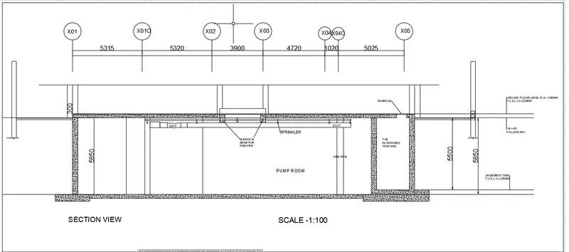
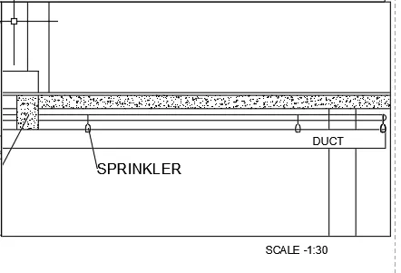
- Create two new view as MANHOLE, SPRINKLER, INDUSTRIAL SECTION
STEP 2
LAYOUT
- Using the LAYOUT command create layout with four viewports
- Open the layout tab , rename the layout as INDUSTRIAL SECTION
- Delete the existing viewport
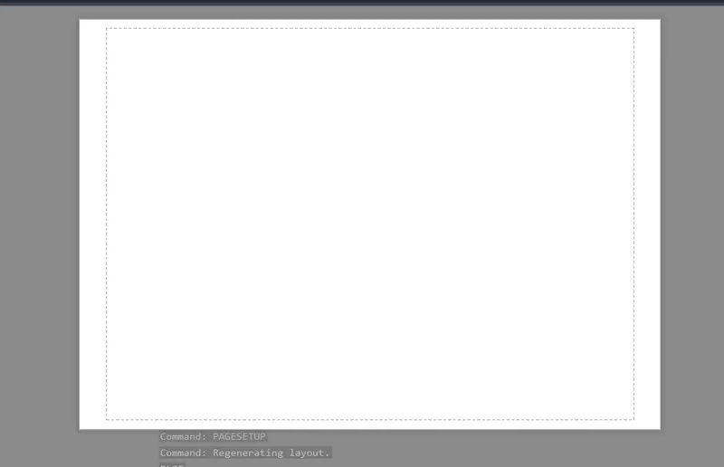
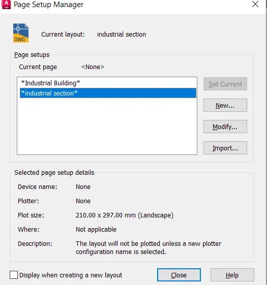
- Using page setup manager select INDUSTRIAL SECTION then select the modify from that
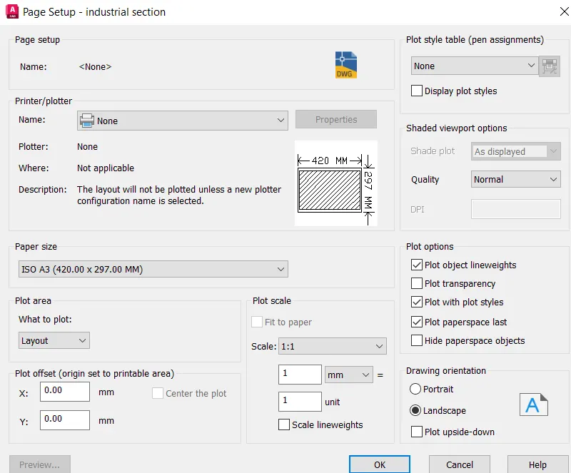
- Give the paper size as A3 in the dialogbox that apperas and make it as current
- Using the MV command create 3 viewports
- Using the "MS" command for model space
- Click on the viewport in which we need to set the drawing
- Go to the view manager and then select MANHOLE and then set it as current then apply then ok
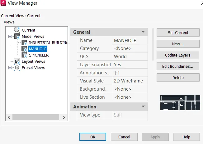
- MAN HOLE view will be displayed
- Zoom in the drawing
- Give the scale as 1:30 and then lock the viewport so that the further zooming will not change the scale
- Similarly we can do this in the other viewport also
STEP 3
PLOT
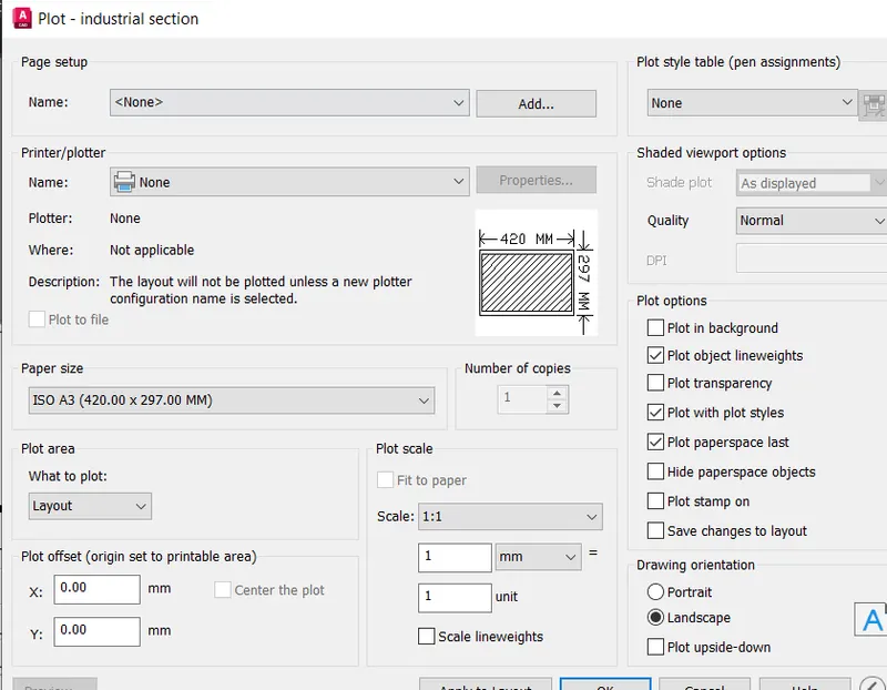
- Using the "PLOT" command plot dialog box is apperaed
- Give the name as DWG TO PDF and set the paper size as ISO A3
- Select what to plot as layout
- orientation is given as landscape and select the pen assignment as "Monochrome "
RESULT
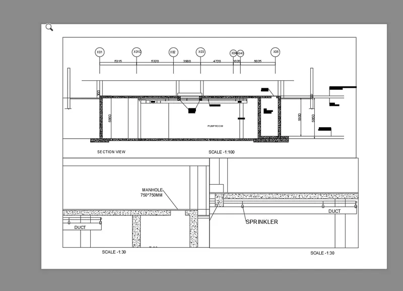
- Different views of INDUSTRIAL SECTION is created
- Layout with 3 viewports with A3 Sheet is created
- Plot is created
-------------------------------------------------------------------------------------------------------------------------------------------