Creation of Multiple viewports, Scaling the drawing and setting in Template in AutoCad
1. Aim: To create the layout of the plan and section given in the attachment.
Introduction: To create the layout of the plan and section which is given in the challenge-7 using template and mArch.dwt in Autoca.
Procedure:
- First we need to set the layout page in which we are going to set the drawing.
- Then we have to create separate layer in which we are going to upload in the layout.
- We can create a View ports separately for each section, plan whatever we require in the layout.
- So that it is easy to insert the drawing in the layout area with the view port command and mv command.
- For this we need to set the page set up in the layout in which page we are going to insert the drawing.
- And the page set up is ready as shown in the below attachment.
-
- After creating the page set up, when you click on the layout there will be an automactic page coming in the layout.
- This existing page we have to delete it and we have to create new page set up as per our drawing size.
- Then we have to insert the drawing by using MV command in the layout page.
- Then all the existing drawings in the page will appear here in the layout page.
- There are 2 setup MS and PS and these are model space and page space.
- Model space means the drawing area and the page space means the out side of the model space area.
- After creating this model space, we need to zoom out the drawing area at which area we need to insert in the drawing.
- Here by using view ports we can easily insert the drawing in the layout page.
- And the scale should be in the ratio of 1:50 which is given in the figure.
- After inserting the drawing, the page layout is as shown below.
-
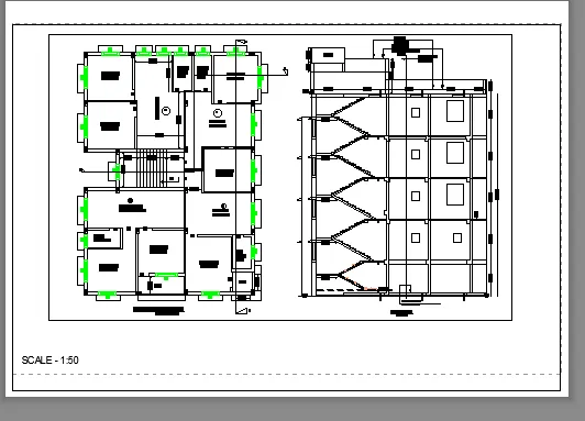
- Then after inserting the drawing, there is a detailed table which is attached in the layout.
- For this we have to create the table or by using table command also we can insert the table.
- In this table we have to provide the information about the drawing.
- And also any revision drawings are there, by using this table we can easily understand the drawing.
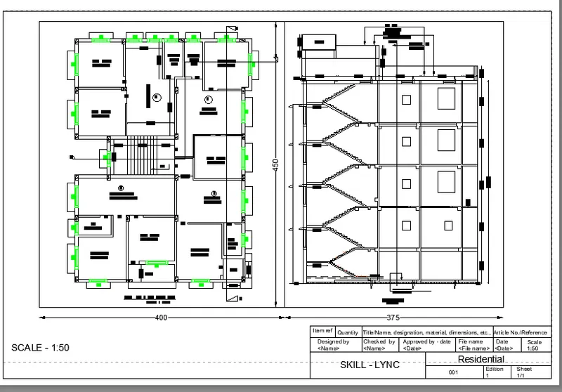
- After creating all these, finaly drawing is attahched in the result.
Result:
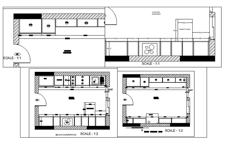
2. Aim: To create the layout of the kitchen drawing.
Introduction: To create the layout of the kitchen drawing as shown in the challenge 9 by using A4 page layout.
Procedure:
- First we need to set the layout page in which we are going to set the drawing.
- Then we have to create separate layer in which we are going to upload in the layout.
- For this we need to set the page set up in the layout in which page we are going to insert the drawing.
- And the page set up is ready as shown in the below attachment.
-

- After this layout set up page, we need to insert the drawing in the layout as in the given figure.
- For this by using MV command, we have to insert in the page layout.
- After creating this mv command, total drawing will appear in the layout sheet.
- Then by using ms command we have to adjust the drawing at which point we need to insert.
- And also, we need to check the scale factor also which is in the given figure.
- After this one drawing is ready which is attached below.
-
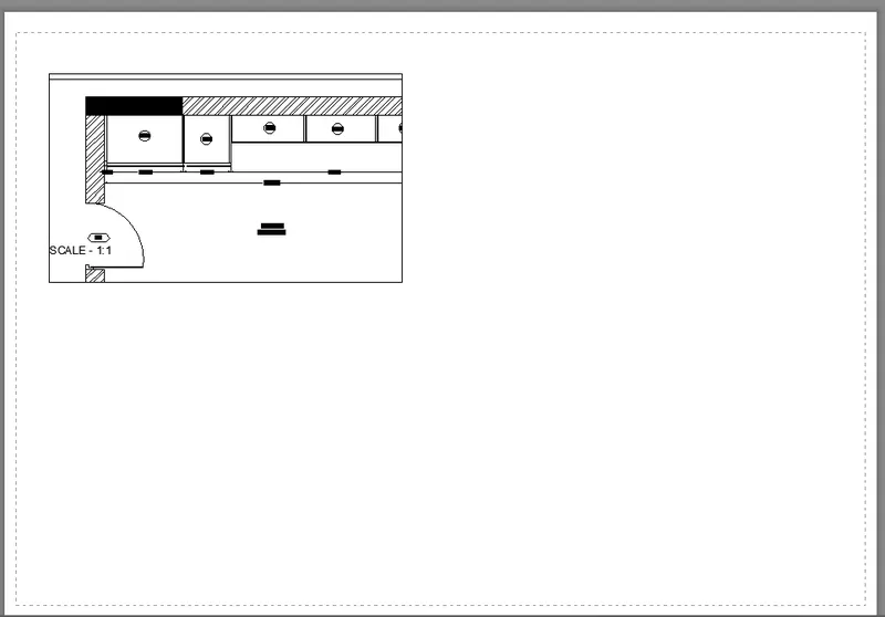
- In the same way, we have to upload another drawing in the layout area.
- After creating this mv command, total drawing will appear in the layout sheet.
- Then by using ms command we have to adjust the drawing at which point we need to insert.
- And also, we need to check the scale factor also which is in the given figure.
- After this one drawing is ready which is attached below.
-
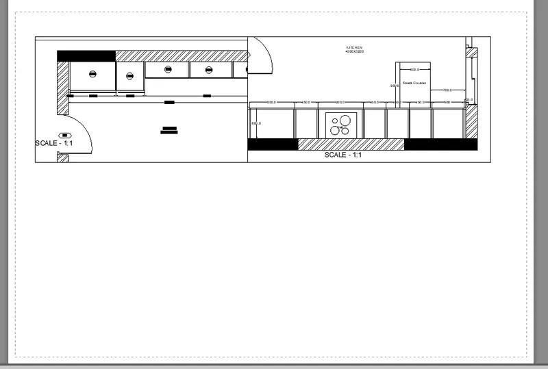
- Now 2 portions are ready which is like in the given attachment.
- After placing the drawing by using mv command, we have to lock the drawing by using properties.
- So that the drawing cannit move later if we move again in the page layout.
- Also if we donnot lock, by moving the drawing scale factor also gets changed.
- And final drawing is ready which is attached in the result.
Result:
3. Aim: To create the layout of the section which is created in the challenge-9.
Introduction: To create the layout of the section which is created in the challenge 9 by using MV command and multiple view ports.
Procedure:
- First we need to set the layout page in which we are going to set the drawing.
- Then we have to create separate layer in which we are going to upload in the layout.
- For this we need to set the page set up in the layout in which page we are going to insert the drawing.
- And the page set up is ready as shown in the below attachment.
-
- After this layout set up page, we need to insert the drawing in the layout as in the given figure.
- For this by using MV command, we have to insert in the page layout.
- After creating this mv command, total drawing will appear in the layout sheet.
- Then by using ms command we have to adjust the drawing at which point we need to insert.
- And also, we need to check the scale factor also which is in the given figure.
- After this one drawing is ready which is attached below.
-
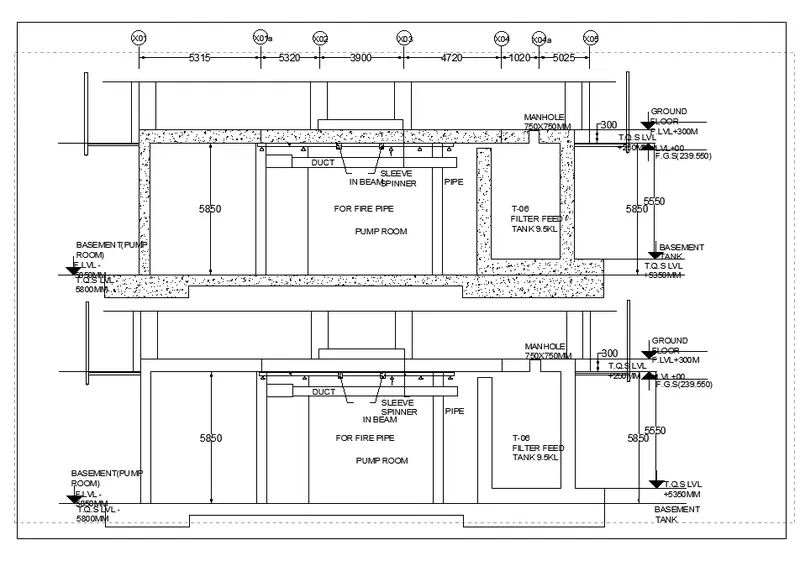
- After placing the drawing by using mv command, we have to lock the drawing by using properties.
- So that the drawing cannit move later if we move again in the page layout.
- Also if we donnot lock, by moving the drawing scale factor also gets changed.
- And final drawing is ready which is attached in the result.
Result: