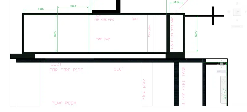
Creation of Multiple viewports, Scaling the drawing and setting in Template in AutoCad
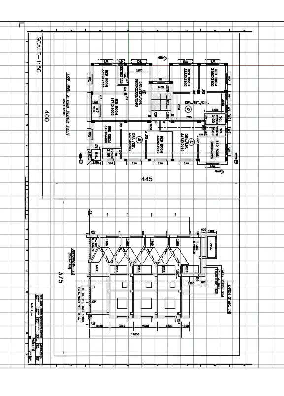
AIM:-To create layout of plan and section a of challenge 7 using template tutotrial march .dwt. use the mv command to create the view port used in the ATTEDIT to edit the information
Commands used:-Line
- POLYGOn
- rectangle
- Circle
- Ellipse
- ERAse
- Copy
- MIrror
- Offset
- Extend
- Array
- Move
- SCale
PROCEDURE:-
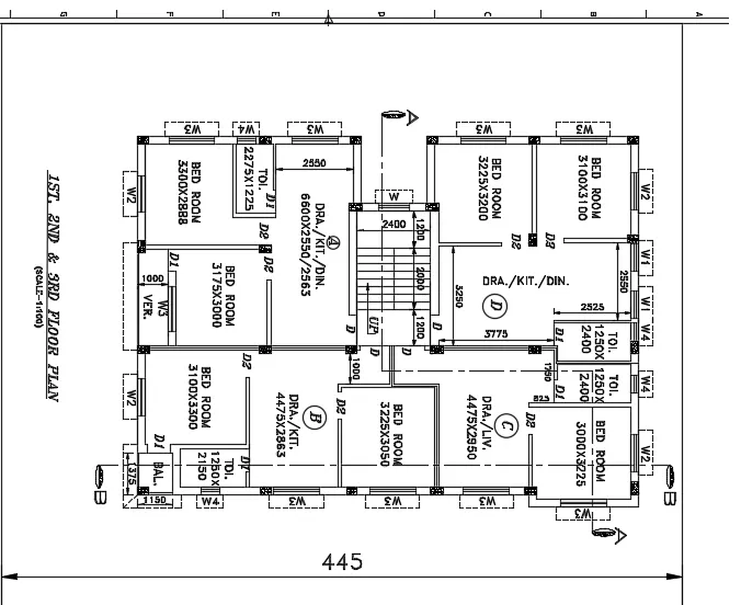
- ARchitectural drawing:- (floor plan)
- Draw a rectangle of 60' and 20' than explode and
- offset 9" for outer walls and using the line offset trim
- Extend the and draw the floor plan
- Now draw the windows using line command and rectangle
- USe copy command`
- Windows are drawn by Using Line command
- Section lines are drawn by using layer and changing the layer type
- FOr hatching the coolumns tyoe hatch in the command box -open setting - select pattern-select patternas air -CONC-select global scale
- ofset it to distance of 4"
- In command prompt type rec 2'*2'
- In command prompt type rec to draft the columns
- IN ribbon tab >annotate >text to text the given dimension
- Now ADD text and name the doors and windows and dimensions the plot size using D text and dimlin command
- Dimension-for drawing dimension using dimension tool in the ribbon
SECTIONAL VIEW:-
- offset 9" for outer walls and using the line offset trim
- Extend the and draw the floor plan
- Now draw the windows using line command and rectangle
- USe copy command`
- Windows are drawn by Using Line command
- Section lines are drawn by using layer and changing the layer type
- FOr hatching the coolumns tyoe hatch in the command box -open setting - select pattern-select patternas air -CONC-select global scale
- ofset it to distance of 4"
- In command prompt type rec 2'*2'
- In command prompt type rec to draft the columns
- IN ribbon tab >annotate >text to text the given dimension
- Now ADD text and name the doors and windows and dimensions the plot size using D text and dimlin command
- Dimension-for drawing dimension using dimension tool in the ribbon
RESULT:-
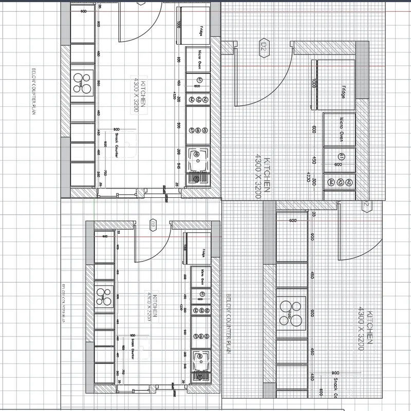
AIM:- TO create a layout of kitchen drawn in challenge 9 and use A4 size page for layout and take a plot
INTRODUCTION:- Kitchen layout is the most important part of designing your perfect kitchen .Its the layout that will determine how you cook,how you eat and how you socialise
Command used:-
- LIMITS COMMAND
LINE COMMAND - OFFSET COMMAND
- HATch command
- DImlinear
- UNiTS
- Extend
- FIllet
- object snap
PROcedure:-
- Units are set to mm
- Limits and limmax are also set up
- Zoom command is also used
- tye rec and dimenions are 4734*3688mm
- Type offset and offset it to distnce of 250mm
- Using arc and lijnes door is drawn
- In the command prompt type hatchg to hatch the model
- Specify the centere as 10,10 and radius 452
- Offset from top of dimensions 12 and 488 mm
- In the command line type offset
- Create the offset from the side at the distance of 608.75 and 365
- In the command line type L and by increasing the transparency to create wall surface
- By using hatch and give scale 20
- In the command line type q leader to mention the annot
- Create the offset from the side at the distance of 608.75 and 365
- Offset from top of dimensions 12 and 488 mm
- In the command line type offset
- Create the offset from the side at the distance of 608.75 and 365
- IN the command prompt offset it to horizontal distance of 350,450,900,450,450,560
- Now offset it to vertical distance of 600mm
- Place all the required elements in respected layers
AIM:- TO create a layout of section created in challenge 9 and take a plot
INtroduction:-
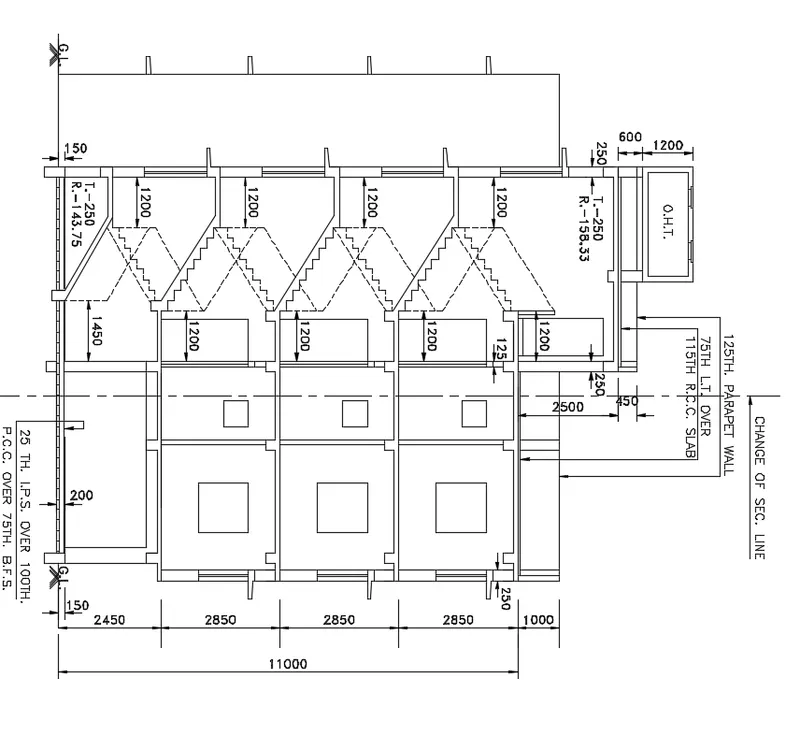
- In reference to architectural building ,the term section typically describes a cut through the body of a building ,perpendicular to the horizon line , asection drawing is one that shows a vertical cut transpecting typically along the proimary axis an object or building.
- A section diagram is a view of the building that slices through the building to better see the specific aspect of the building better
- This drawing is particulary interseting because it cuts through
Commands used:-
- LIMITS COMMAND`
- OFFSET COMMAND
- HATch command
- DImlinear
- UNJTS
- Extend
- FIllet
- object snap
- OFFSET COMMAND
- HATch command
- DImlinear
- UNiTS
- Extend
Step-1:-
- first we have to draw the x- line at annoy point on the screen
- next offset the line to top a distance of 5850 mm and we have to do offset of last offset line to the distance of 300mm
- Comming to the drawing the elevation of residential building first we draw the horizontal line using line command with the length of 11574mm
- NExt we need to draw the another line frrom the previous line vertically with length of 1200mm
- NExt we have to draw the line horizontally towards from previous line with the length of 12150mm at the top
- NExt we need to draw the sunshades provided in the drawing
- Next we draw the windows with standard construction dimensions with the help of line command
- Next draw the balcony part using the line command ,offset command and trim command
- Next we draw the remaining architectural elements using line command rectangle comamd and offset comm
STEP-2:-
- NExt we need to draw the sunshades provided in the drawing
- Next we draw the windows with standard construction dimensions with the help of line command
- Next draw the balcony part using the line command ,offset command and trim command
- Next we draw the remaining architectural elements using line command rectangle comamd and offset comm
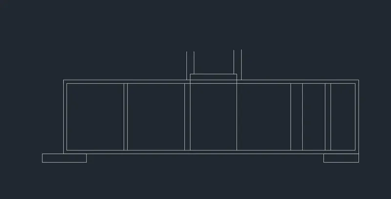
STEp-3:-
- NExt we need to draw the another line frrom the previous line vertically with length of 1200mm
- NExt we have to draw the line horizontally towards from previous line with the length of 12150mm at the top
- NExt we draw a rectangle at the top of buildingds
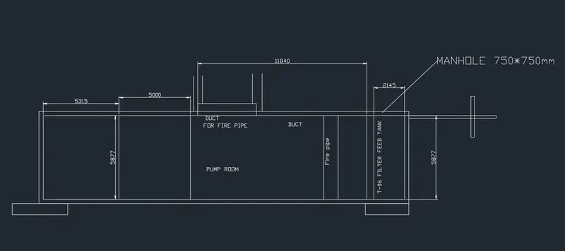
:-
- PRovide hatching wherever required
- provide layers
- layers of dimensions and text are provided
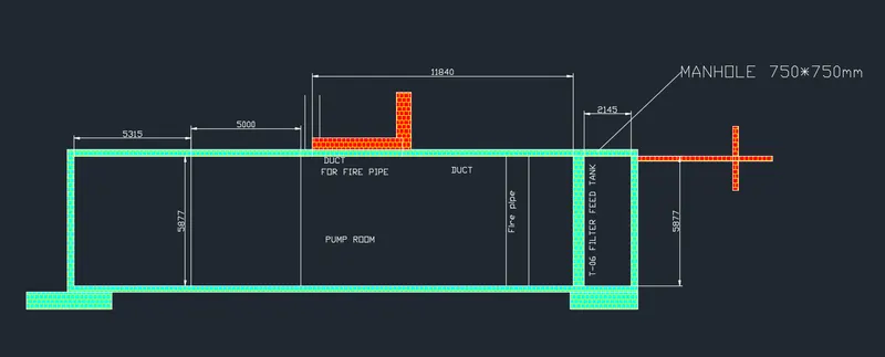
STEP-5:- The sectional view of building of the industrial building is drawn successfully in the autocad in detail.
RESULT:-