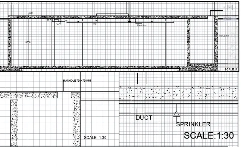
Creation of Multiple viewports, Scaling the drawing and setting in Template in AutoCad
Q1:
Aim: To create layout of the plan and section using template Tutorial mArch.dwt in AutoCAD
Procedure:
In the command prompt type "UNITS" and press enter.
Select the units as "decimal" and insertion scale as "Millimeters".
Click ok.
Type "limits" in the command prompt and press enter.
Select "off" from the command prompt.
Type "Xline" in the command promp and press enter.
Type "v" and press enter.
Place the vertical xline anywhere in the workspace and press "esc".
Type "offset" in the command prompt and press enter.
Specify the off set distance as 230. and select the vertical line to offset.
Press "esc".
Type "Xline" in the command promp and press enter.
Type "H" and press enter.
Place the horizontal xline anywhere in the workspace and press "esc".
Type "offset" in the command prompt and press enter.
Specify the off set distance as 230. and select the horizontal line to offset.
Press "esc".
Press the spacebar two times to activate offset command and also to mention the distance.
Specify the required length to offset.
Repeat the same procedure as per required dimensions.
Type "trim" in the command prompt and press enter.
Select the lines to trim to get the required dimensions.
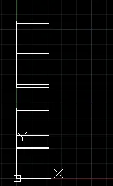
Type "offset" in the command prompt and press enter.
Specify the offset distance and press enter.
Select the lines to offset.
Press esc.
Again type "offset" in the command prompt.
Specify the offfset distance and press enter.
Specify the distance and press enter.
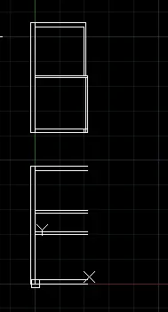
Select line tool from ribbon tab.
Specify the starting point as endpoint in the top line.
Draw the line in horizontal direction as per the dimension given in the figure.
Press esc.
Again use line tool from ribbon tab.
Draw vertical lines to indicate room partions.
Press esc.
Type offset in the command prompt and press enter.
Specify the offset distance for making internal walls.
Select the lines to offset.
Press esc.
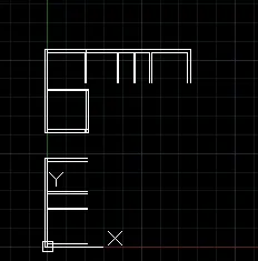
Select line tool from ribbon tab.
Specify the starting point as endpoint in the bottom line.
Draw the line in horizontal direction as per the dimension given in the figure.
Press esc.
Again use line tool from ribbon tab.
Draw vertical lines to indicate room partions.
Press esc.
Type offset in the command prompt and press enter.
Specify the offset distance for making internal walls.
Select the lines to offset.
Press esc.
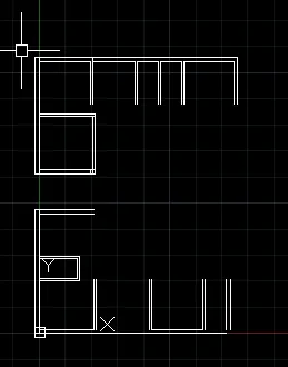
Select line tool from ribbon tab.
Sepcify the starting point as end point of previously created line.
Draw a horizontal line as per required length.
Draw a vertical line as per required dimensions.
Draw a horizontal line in negative xdirection as per required dimesnions.
Draw a vertical line in negative y direction as per required dimensions.
Select line tool from ribbon tab.
Sepcify the starting point as end point of previously created line.
Draw a vertical line as per required length.
Press esc.
Type offset in the command prompt and press enter.
Specify the distance and select the previously created line to offset.
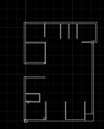
Select reactangle tool from ribbon tab.
Create the reactangle as per the dimensions and orientation required.
Selct the created rectangle and use move command.
Place the rectangle in the required posistions.
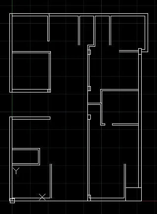
Select line tool from ribbon tab.
Draw horizontal line indicate the wall supporting stairs on both the sides.
Draw lines to specify riser.
Type offset command in the command prompt.
Specify the offset distance and select the lines to offset.
Press esc.
Select line tool from ribbon tab.
Draw lines to create windows and ventilators of required dimensions.
Create windows and ventilators in all the required places as per the given figure.
Click on the layer setting available on the ribbon tab.
Click create layer option, type the layer name as "dotted line".
Select the line type and click load.
From the list available, select the required linetype and click close.
Select the "set currrent layer" option and close the layer properties.
Now, select line tool from ribbon tab.
Draw the lines around windows to indicate sunshade.
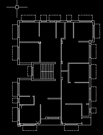
Again use rectangle tool from ribbon tab.
Create rectangle of suitable dimension and orientation.
Place the created rectangle using move command.
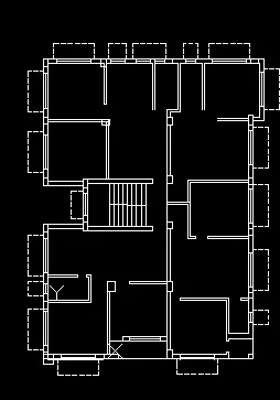
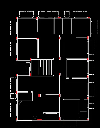
Select hatch tool from ribbon tab.
Selct solid fill from the hatch settings.
Select the required color.
Move the pointer to the column to give hatch.
Repeat the procedure to give hatch to all column markings.
Click on the layer setting available on the ribbon tab.
Click create layer option, type the layer name as "Section line".
Select the line type and click load.
From the list available, select the required linetype and click close.
Select the "set currrent layer" option and close the layer properties.
Now, select line tool from ribbon tab.
Draw the lines as given in the figure.
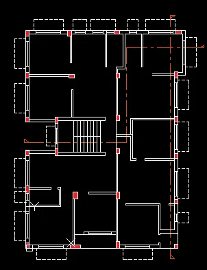
Click on the layer setting available on the ribbon tab.
Click create layer option, type the layer name as "dimension".
Select the line type and click load.
From the list available, select the required linetype and click close.
Select the suitable color
Select the "set currrent layer" option and close the layer properties.
Now, select dimlinear tool from ribbon tab.
Sprecify the starting and end point to display the dimensions.
Repeat the same dim linear tool to specify the dimensions.
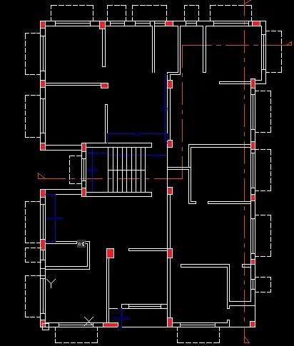
Select the text tool from ribbon tab.
Select "single line text".
Keep the cursor in the place where text has to start and click.
Type the required text.
Move the cursor to the next point where the text has to start and click.
Type the required text.
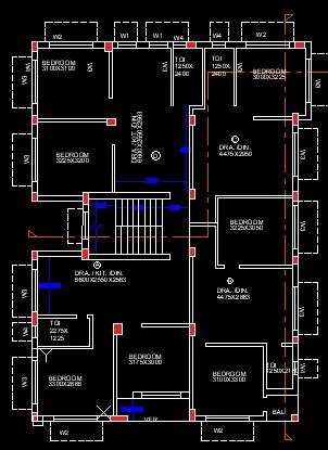
Select the all the text created in the previous step.
From the layer drop down list, select the dimension layer.
Now all the text created comes under dimension layer
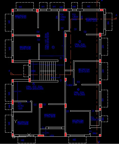
TO DRAW SECTION A-A
Select line tool from ribbon tab.
Draw a borizontal line as per the required dimension.
Again draw a vertical line as per the required dimension.
Draw a borizontal line as per the required dimension.
Select line tool from ribbon tab.
Draw a borizontal line as per the required dimension.
Again draw a vertical line as per the required dimension.
Draw a borizontal line as per the required dimension.
Type offset in the command prompt and press enter.
Specify the required distance to offset and select the object to offset.
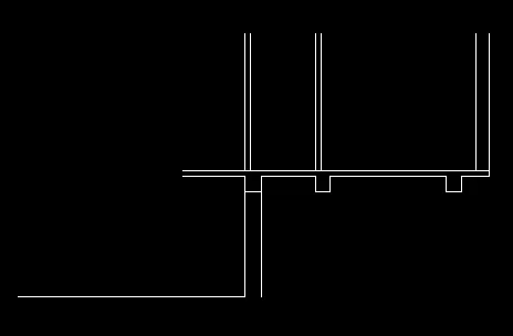
Select the rectangle tool from ribbon tab.
Create a rectangle of required dimension to indicate windows.
Place the cursor in the next point and create a rectangle to indicate ventilation.
Press "esc".
Use line tool from ribbon tab.
Draw the lines to create windows.
Use line tool from ribbon tab to draw sunshade.
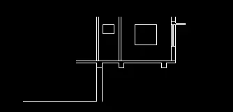
Select line tool from ribbon tab and specify the starting point.
Draw a line of suitable length indicating thread.
Again using line tool draw vertical line indicating riser.
Select the previously created riser and thread.
Type copy in the command prompt and press enter.
Select the suitable base point and press enter.
Place the copied place in the end point of riser.
Repeat the procedure to create stairs.
Use line command to create columns and floorings.
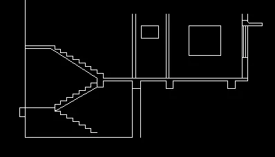
Use line tool from ribbon tab.
Draw vertial line in the recommended position.
Draw a horizontal line at both starting and end point of vertical line.
Press esc.
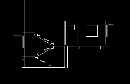
Select the previously created objects such as stairs, windows and floorings.
Type copy in the command prompt and press enter.
Select the suitable base point and move the copied objects in the vertical direction.
Place the in the required position.
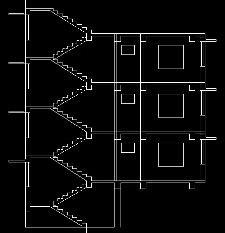
Select the dotted line layer from the layer list.
Select the line tool from ribbon tab.
Daw a line to create hand railing.
Select the created railing and type copy in the command prompt, press enter.
Place the copied object in the suitable position.
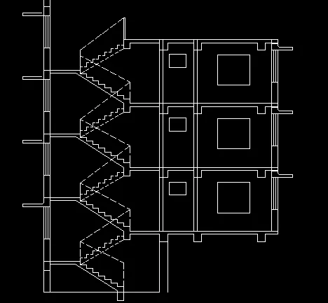
Select rectangle tool from ribbon tab.
Draw a rectangle indicating over head tank.
Press esc.
Type offset in the command prompt and press enter.
Specify the suitable offset distance.
Click on the object to offset.
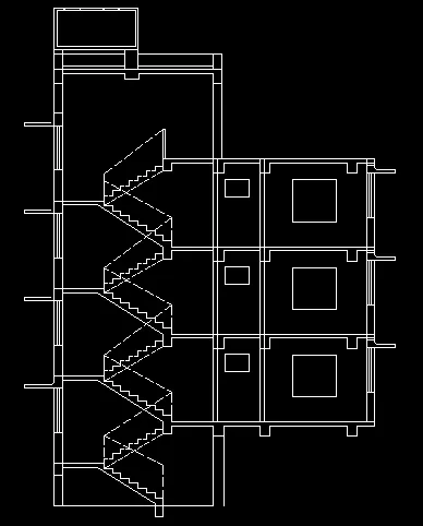
Select line tool from ribbon tab.
Specify the starting point near the endpoint of stair.
Draw a vertical line in the upward direction.
Draw a horizontal direction in right direction.
Draw a horizontal direction in downward direction.
Press esc.
Similarly use line command to draw other elements.
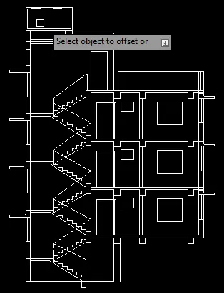
Select line tool from ribbon tab.
Specify the starting point as the bottom left corner point.
Draw a line negative x-direction.
Draw the next line in positive y-direction.
Draw the next line in positive x-direction.
Press esc.
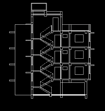
Click on the layer setting available on the ribbon tab.
Click create layer option, type the layer name as "dimension".
Select the line type and click load.
From the list available, select the required linetype and click close.
Select the suitable color
Select the "set currrent layer" option and close the layer properties.
Now, select dimlinear tool from ribbon tab.
Sprecify the starting and end point to display the dimensions.
Repeat the same dim linear tool to specify the dimensions.
Select the text tool from ribbon tab.
Select "single line text".
Keep the cursor in the place where text has to start and click.
Type the required text.
Move the cursor to the next point where the text has to start and click.
Type the required text.
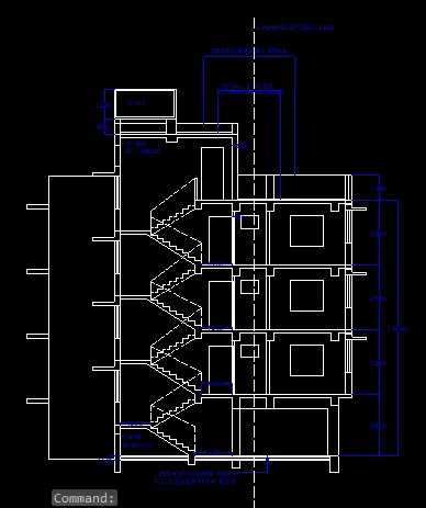
Click on the view in the ribbon tab.
Click on the view port configuration.
Select the viewport configuration.
From the drop down, select 'Two: vertical'.
Adjust the cursor to alter the view until the required is obtained.
Select the scale option and choose the required scale.
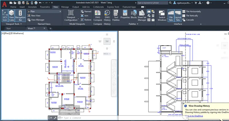
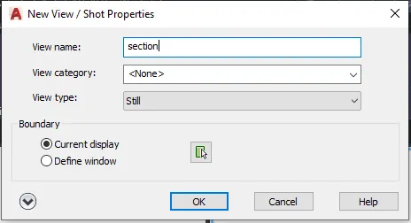
Click on the view and select New view.
Type the name in which you want to select.
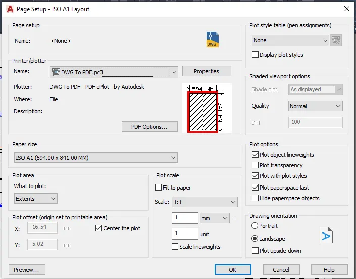
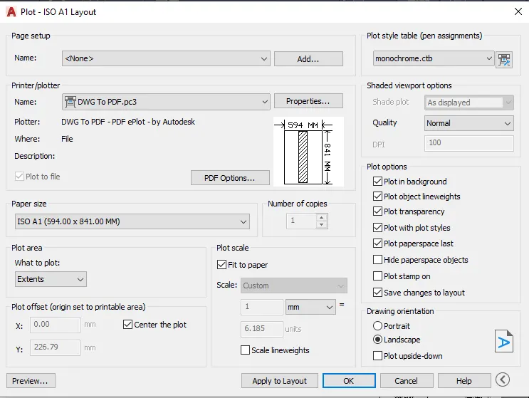
Press ctrl+p to open page setup.
In the page setup select the required paper type and plotter type.
Select the plot style and scale.
Press ok to finish page setup.
Type “layout” in the command prompt and press enter.
Select “New” and enter the name.
Type “Layout” in the command prompt and press enter.
Select template from the options.
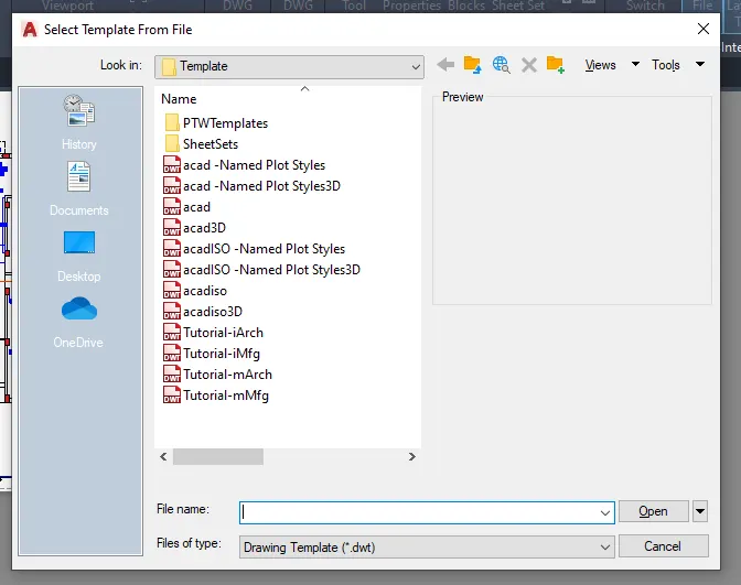
From the template tab select the required Tutorial-mArch and click ok.
Select “ISO A1” and click ok.
Click on the existing view and delete in by right clicking on it.
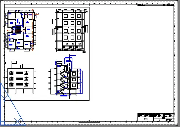
Type MV in the command prompt and press enter.
Select the polygon and draw the required view ports.
Follow the same procedure to create multiple view ports.
Select any view and select view from ribbon tab.
Click on viewport manager and select the saved view.
Similarly follow the same steps to create required by saving the view.
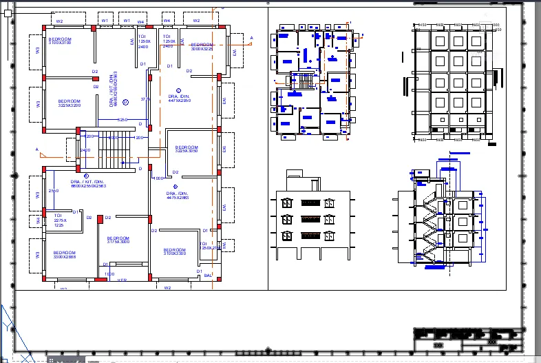
Type MS in the command prompt to enable model space.
Select the scale option and choose the required scale.
Type Pan in the command prompt and press enter.
Using a pan tool, adjust the view.
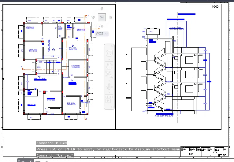
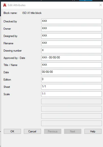
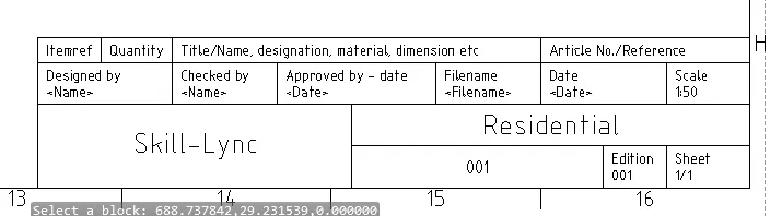
Type ATTEDIT in the command prompt and press enter.
Select the blocks to edit.
Edit blocks dialogue box opens, where the blocks can be edited.
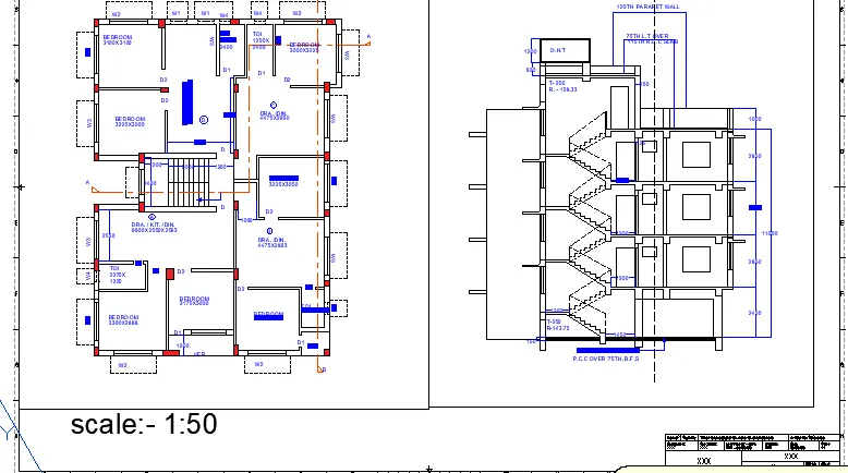
Select the text tool from the ribbon tab and select a single line.
Enter the starting point of text and text angle.
Type the required text in the required places.
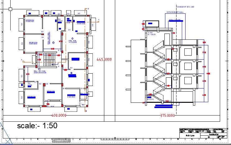
Select dimension tool from ribbon tab.
Select the starting point and the ending point to show the dimensions.
Press ctrl+p to open page setup.
In the page setup select the required paper type and plotter type.
Select the plot style and scale.
Press ok to finish page setup.
Q2:
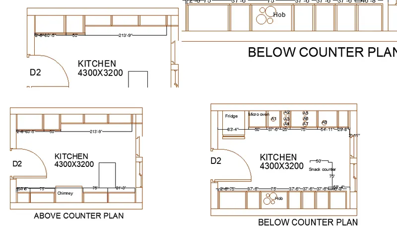
Aim: To create kitchen layout in A4 size paper and plot the same using AutoCAD.
Procedure:
In the command prompt type "UNITS" and press enter.
Select the units as "decimal" and insertion scale as "Millimeters".
Click ok.
Type "limits" in the command prompt and press enter.
Select "off" from the command prompt.
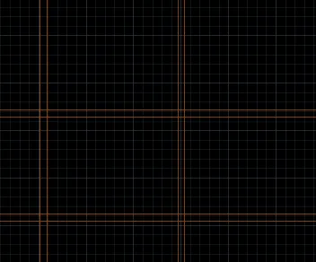
Type "XLine" in the command prompt and press enter.
Tyep "V" in the command prompt and press enter.
Place the vertical xline and press "esc".
Type "XLine" in the command prompt and press enter.
Tyep "H" in the command prompt and press enter.
Place the horizontal xline and press "esc".
Type "offset" in the command prompt and press enter.
Specify the offset distance as 230.
Select the horizontal line to offset.
Now select the vertilcal line to offset.
Type "offset" in the command prompt and press enter.
Specify the offset distance as 4300.
Select the vertical line to offset and press esc.
Type "offset" in the command prompt and press enter.
Specify the offset distance as 3200.
Select the Horizontal line to offset and press esc.
Type "offset" in the command prompt and press enter.
Specify the offset distance as 230.
Select the horizontal line to offset.
Now select the vertilcal line to offset.
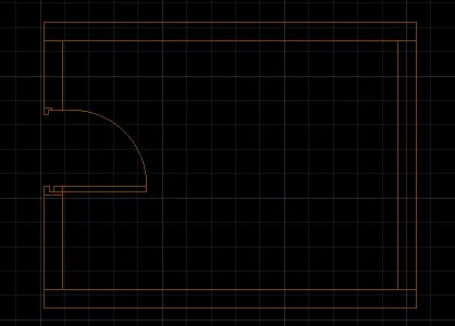
Select trim tool from ribbon tab.
Trim the portion required for sketching the door.
Select arc tool from ribbon tab.
From the drop down, select "start, end and direction".
Now specify the starting and ending point.
Move the cursor to specify the direction of door opening.
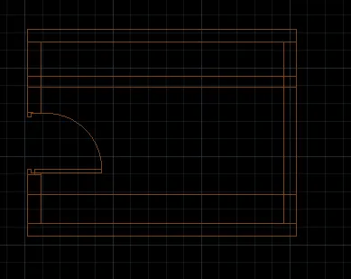
Type "offset" in the command prompt and press enter.
Specify the offset distance as 600.
Select the top horizontal line to offset and press esc.
Type "offset" in the command prompt and press enter.
Specify the offset distance as 800.
Select the top horizontal line to offset and press esc.
Type "offset" in the command prompt and press enter.
Specify the offset distance as 600.
Select the bottom horizontal line to offset and press esc.
Select line tool from ribbon tab.
Specify the starting indicating the position of window.
Use rectangle tool from rtibbon tab to draw the separation.
Again use line tool to draw the next window.
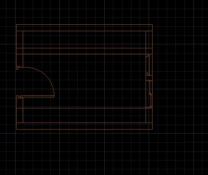
Use line toiol from riibbon tab.
Draw a line of length 800 in the negative y direction.
Use offset command to offset the line upto distance of 1000.
Draw a line of length 550 in the negative y direction.
Use offset command to offset the line upto distance of 600.
Draw a line of length 550 in the negative y direction.
Use offset command to offset the line upto distance of 450.
Draw a line of length 550 in the negative y direction.
Use offset command to offset the line upto distance of 300.
Draw a line of length 550 in the negative y direction.
Use offset command to offset the line upto distance of 900.
Draw a line of length 550 in the negative y direction.
Use offset command to offset the line upto distance of 300.
Draw a line of length 550 in the negative y direction.
Use offset command to offset the line upto distance of 945.
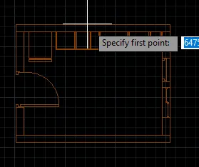
Draw a line of length 550 in the negative y direction.
Use offset command to offset the line upto distance of 900.
Draw a line of length 550 in the negative y direction.
Use offset command to offset the line upto distance of 450.
Draw a line of length 550 in the negative y direction.
Use offset command to offset the line upto distance of 900.
Draw a line of length 550 in the negative y direction.
Use offset command to offset the line upto distance of 450.
Draw a line of length 550 in the negative y direction.
Use offset command to offset the line upto distance of 450.
Draw a line of length 550 in the negative y direction.
Use offset command to offset the line upto distance of 450.
Draw a line of length 550 in the negative y direction.
Use offset command to offset the line upto distance of 560.
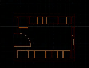
Select the entire object in the workspace.
Type "copy" in the command prompt and press enter.
Select the bottom left corner point as base point.
Move the copy of the object in the positive X-direction and place it.
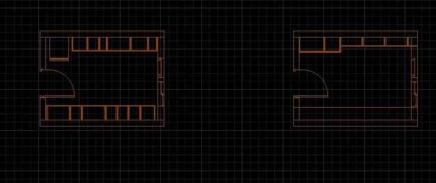
Similarly draw a line of length 550 in the negative y direction.
Use offset command to offset the line upto distance of 965.
Draw a line of length 550 in the negative y direction.
Use offset command to offset the line upto distance of 600.
Draw a line of length 550 in the negative y direction.
Use offset command to offset the line upto distance of 865.
Draw a line of length 550 in the negative y direction.
Use offset command to offset the line upto distance of 865.
Draw a line of length 550 in the negative y direction.
Use offset command to offset the line upto distance of 865.
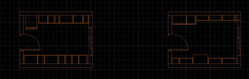
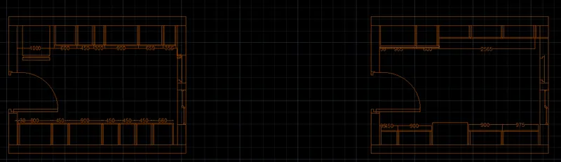
Selectb the dimension tool from the ribbon tab.
Sprecify the starting point and end point.
Move the cursor to adjust the position of dimnesions.
Press "c" or click "continue" in the command prompt.
Select the basepoint from the dimensioning has to continue.
Move the cursor to next point and click to display the dimensions.
Similarly repeat the same procedure to display the dimensiosn.
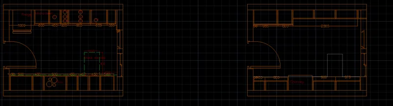
Select text tool from ribbon tab.
From the drop down, select single line text.
Place the pointer where the text has to be inserted and click.
Type Fridge and click on the next point where the text has to be inserted.
Similarly enter all the text
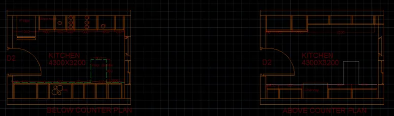
Select text tool from ribbon tab.
From the drop down, select single line text.
Place the pointer where the text has to be inserted and click.
Type Kitchen "4300x3200".
In the annotate tool, click manage text style.
In the dialogue box chnage the text height and click apply.
Select the text and go the annotate tool, select standard.
Now the text height is changed.
Select text tool from ribbon tab.
From the drop down, select single line text.
Place the pointer where the text has to be inserted and click.
Type Kitchen "4300x3200".
In the annotate tool, click manage text style.
In the dialogue box chnage the text height and click apply.
Select the text and go the annotate tool, select standard.
Now the text height is changed.
Click on the view in the ribbon tab.
Click on the view port configuration and select the required configuration.
Adjust the cursor to alter the view until the required is obtained.
Select the scale option and choose the required scale.
Click on the view and select New view.
Type the name in which you want to select.
Type “layout” in the command prompt and press enter.
Select “New” and enter the name.
Type “Layout” in the command prompt and press enter.
Select template from the options.
From the template tab select the required template and click ok.
Select “ISO A1” and click ok.
Click on the existing view and delete in by right clicking on it.
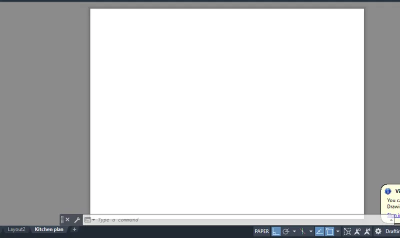
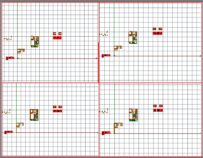
Type MV in the command prompt and press enter.
Select the polygon and draw the required view ports.
Follow the same procedure to create multiple view ports.
Select any view and select view from ribbon tab.
Click on viewport manager and select the saved view.
Similarly follow the same steps to create required by saving the view.
 =
=
Type MS in the command prompt to enable model space.
Select the scale option and choose the required scale.
Type Pan in the command prompt and press enter.
Using a pan tool, adjust the view.
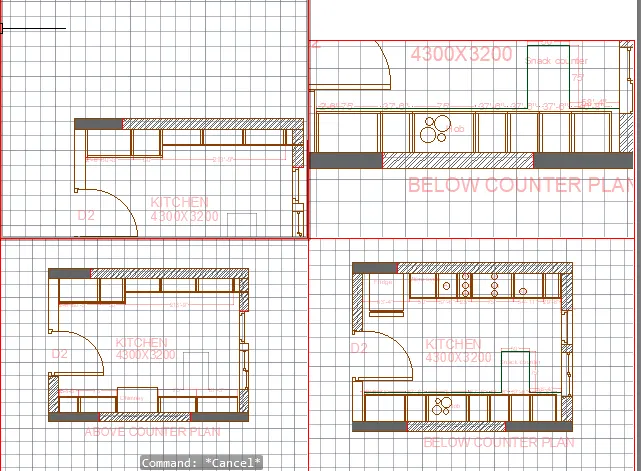
Select the text tool from the ribbon tab and select a single line.
Enter the starting point of text and text angle.
Type the required text in the required places
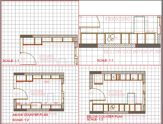
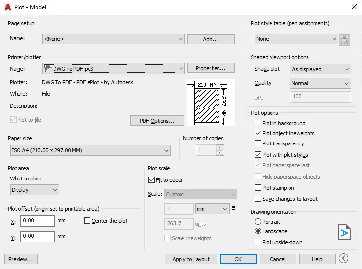
Press ctrl+p to open page setup.
In the page setup select the required paper type and plotter type.
Select the plot style and scale.
Press ok to finish page setup.
Scale:
Select the text tool from the ribbon tab and select a single line.
Enter the starting point of text and text angle.
Type the required text in the required places.
Q3:
Aim: To create layout of section using multiport and scale tool in AutoCAD.
Procedure:
Type "UNITS" in the command prompt and press enter.
In the unit tab, select the type as "Architectural" and insertion scale as "inches".
Click ok.
Select rectangel tool from the ribbon tab.
Specify the starting point as (0,0) and press enter.
Specify the starting point in the workspace.
Select line tool from ribbon tab.
Draw a horizontal line as per the required dimension.
Again draw a vertical line as per the required dimension.
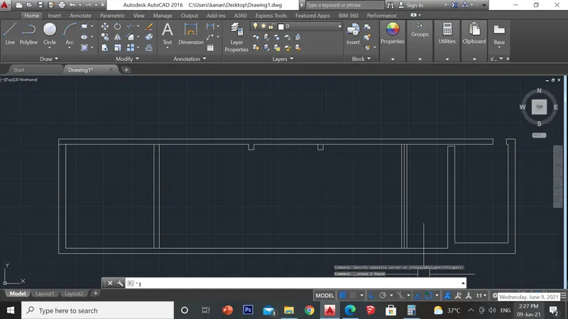
Type offset in the command prompt and press enter.
Enter the required offset distance and press enter.
Select the previously created lines to offset.
Press esc.
Draw a horizontal line as per the required dimension.
Type offset in the command prompt and press enter.
Enter the required offset distance and press enter.
Select the line to offset (i.e) the previous created lines.
Press esc.
Type offset in the command prompt and press enter.
Enter the required offset distance and press enter.
Select the line to offset (i.e) the previous created lines.
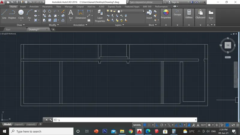
Type offset in the command prompt and press enter.
Enter the the required offset distance.
Select the top horizontal line to offset.
Press esc.
Select line tool from ribbon tab.
Specify the starting point as (0,0).
Draw a vertical line of required distance.
Press esc.
Type offset in the command prompt and press enter.
Enter the the required offset distance.
Select the vertical line to offset.
Press esc.
Select line tool from ribbon tab.
Specify the starting point as (0,0).
Draw a vertical line of required distance.
Press esc.
Type offset in the command prompt and press enter.
Enter the the required offset distance.
Select the vertical line to offset.
Press esc.
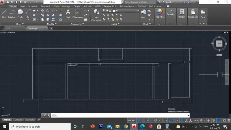
Select line tool from ribbon tab.
Specify the starting point as (0,0).
Draw a vertical line of required distance.
Press esc.
Type offset in the command prompt and press enter.
Enter the the required offset distance.
Select the vertical line to offset.
Press esc.
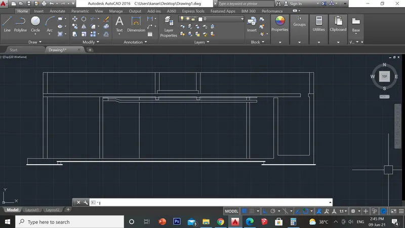
Select hatch tool from ribbon tab.
From the ribbon tools, click on the drop down icon.
From the list, select the suitable hatch.
Place the cursor in the enclosed area to create hatch.
Repeat the same procedure to hatch in the required place.
After finishing click on close hatch creation.
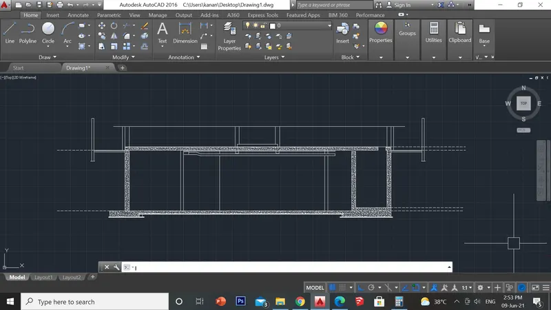
Select the dimension tool from the ribbon tab.
Select the starting point using cursor.
Select the endpoint and press enter.
Now the dimension will be displayed.
To dispaly the various dimensions use the same dimension tool from ribbon tab.
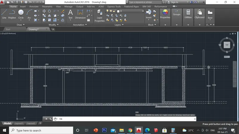
Select text tool from the ribbon tab and press enter.
From the drop down select the single line text.
Place the cursor at which the text has to be entered and click.
Enter the text angle as zero and press enter.
Now the cursor appears in the required place.
Type the required text.
Repeat the procedure to enter text in the required places.
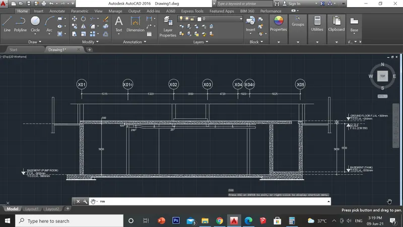
Click on the view in the ribbon tab.
Click on the view port configuration and select the required configuration.
Adjust the cursor to alter the view until the required is obtained.
Select the scale option and choose the required scale.
Click on the view and select New view.
Type the name in which you want to select.
Type “layout” in the command prompt and press enter.
Select “New” and enter the name.
Type “Layout” in the command prompt and press enter.
Select template from the options.
From the template tab select the required template and click ok.
Select “ISO A1” and click ok.
Click on the existing view and delete in by right clicking on it.
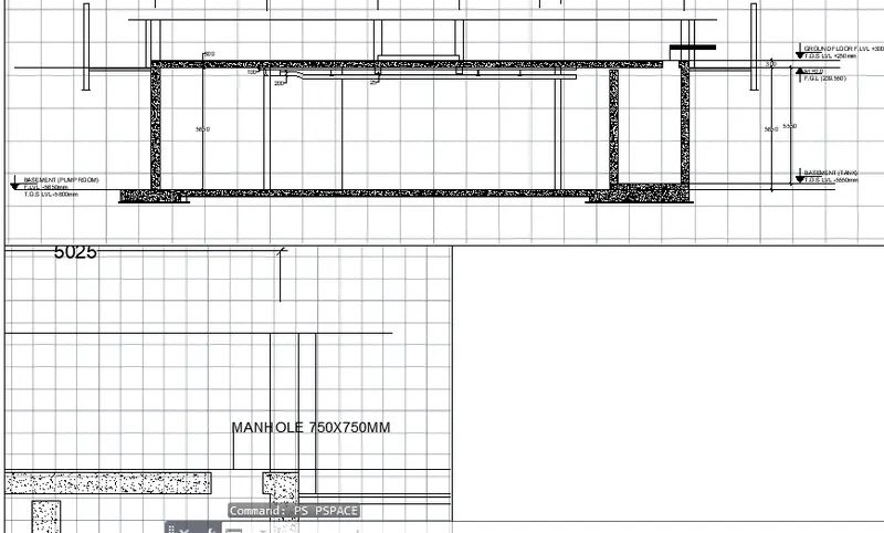
Select the polygon and draw the required view ports.
Follow the same procedure to create multiple view ports.
Select any view and select view from ribbon tab.
Click on viewport manager and select the saved view.
Similarly follow the same steps to create required by saving the view.
Type MS in the command prompt to enable model space.
Select the scale option and choose the required scale.
Type Pan in the command prompt and press enter.
Using a pan tool, adjust the view.
Select the text tool from the ribbon tab and select a single line.
Enter the starting point of text and text angle.
Type the required text in the required places.
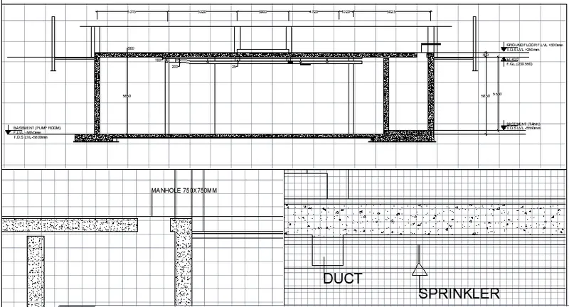
Enter the starting point of text and text angle.
Type the required text in the required places.