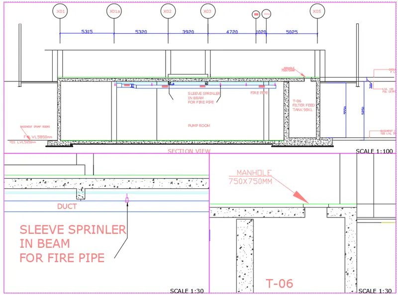
Creation of Multiple viewports, Scaling the drawing and setting in Template in AutoCad
1Q]
AIM: -
Create a LAYOUT of the Plan and Section A-A of the project 7 by using the template
Tutorial-march.dwt
Use the MV command to create the viewport
Use ATTEDIT command to the information.
Take a Plot.
PROCEDURE: -
Type LAYOUT
Select Template
Choose Tutorial-mArch.dwt from the folder
Select ISO A1 layout and press OK
ISO A1 layout is created.
Type LINE
Draw a Rectangle of Size 400 x 445 units as given in figure.
Draw a Rectangle of size 375 x 445 units next to it.
Type MVIEW
Plot viewport on the Rectangle drawn 400 x 445 units.
Plot another viewport on the Rectangle 375 x 445 units.
Type MS (model space)
Select one of the viewports and adjust the floor plan to the display
Set the scale to 1:50
Type MVIEW
Select Lock option
Turn on the Viewport locking and select the viewport to lock
Press Enter
Type MS (model space)
Select the other viewport and adjust the Section A-A to the display
Set the scale to 1:50
Type MVIEW
Select Lock option
Turn on the Viewport locking and select the viewport to lock.
Press Enter
Type ATTEDIT
Select the block to edit the Attributes.
Provide the details
Checked by: Name
Owner: SKILL-LYNC
Designed by: Name
Filename: Name
Drawing No: 001
Approved by-Date: date
Title/Name: RESIDENTIAL
Edition: 1
Sheet: 1/1
Scale: 1:50
Press OK
The data changes on the Layout.
Type PLOT
Plot dialogue box opens
Page setup:
Name: Write the name of the file
Printer
Name: DWG TO PDF.pc3
Paper size; ISO A1
Plot Area: Layout
Drawing Orientation: landscape
Scale: 1:1
Select Preview to check
Right click on the preview page and select plot
Save the file at the desired Location.
RESULT: -
We created the Floor Plan and Section A-A Layout on A1 Size paper
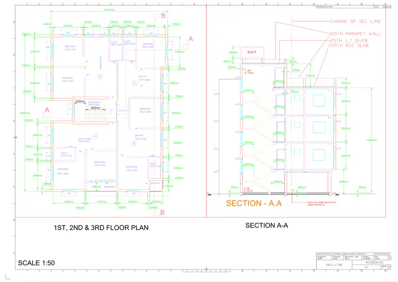
2Q]
AIM: -
Create a Layout of the Kitchen drawn in Challenge 9
Use A4 size for the Layout.
Take a plot.
PROCEDURE: -
Type LAYOUT
Select NEW
Enter the New layout name: KITCHEN
KITCHEN Layout is created.
Type PAGESETUP
Select New
Provide the name: KITCHEN
Page Setup Dialogue Box opens.
Select Paper size: ISO A4
Press OK.
Type MVIEW
Select option 4
Click on the Top left corner and drag to the bottom right corner
Now the Layout Divides into 4 equal viewports.
Type MS (model space)
Select one of the viewports and adjust the Kitchen-Below Counter plan to the display
Set the scale to 1:50
Type MVIEW
Select Lock option
Turn on the Viewport locking and select the viewport to lock
Press Enter
Type MS (model space)
Select one of the viewports and adjust the Kitchen-Above Counter plan to the display
Set the scale to 1:50
Type MVIEW
Select Lock option
Turn on the Viewport locking and select the viewport to lock
Press Enter
Type MS (model space)
Select one of the viewports and adjust the Kitchen plan to the display as shown in the figure
Set the scale to 1:30
Type MVIEW
Select Lock option
Turn on the Viewport locking and select the viewport to lock
Press Enter
Type MS (model space)
Select one of the viewports and adjust the Kitchen plan to the display as shown in the figure
Set the scale to 1:30
Type MVIEW
Select Lock option
Turn on the Viewport locking and select the viewport to lock
Press Enter
Type PLOT
Plot dialogue box opens
Select the File
Page setup:
Name: Write the name of the file
Printer
Name: DWG TO PDF.pc3
Paper size; ISO A4
Plot Area: Layout
Drawing Orientation: landscape
Scale: 1:1
Select Preview to check
Right click on the preview page and select plot
Save the file at the desired Location.
RESULT: -
We created the Kitchen Layout on the A4 size.
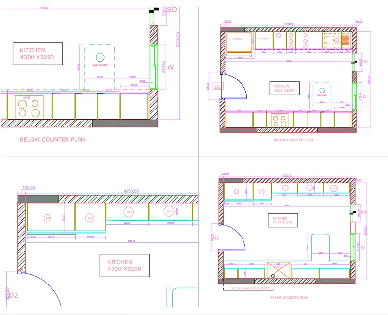
3Q]
AIM: -
Create a Layout of the Industrial section drawn in Challenge 9
Create Multiple Viewports as given in figure.
Take a plot.
PROCEDURE: -
Type VIEW
View Manager Dialogue Box opens.
Select New
New View Dialogue box opens.
View Name: Section view
View Category: None
View Type: Still
Boundary: Current Display
Press OK
Type VIEW
View Manager Dialogue Box opens.
Select New
New View Dialogue box opens.
View Name: Manhole view
View Category: None
View Type: Still
Boundary: Define window
Select the desired view
Press OK
Type VIEW
View Manager Dialogue Box opens.
Select New
New View Dialogue box opens.
View Name: Sprinkler view
View Category: None
View Type: Still
Boundary: Define window
Select the desired view
Press OK
Type LAYOUT
Select NEW
Enter the New layout name: Industrial Section
Industrial Section Layout is created.
Type PAGESETUP
Select New
Provide the name: Section1
Page Setup Dialogue Box opens.
Select Paper size: ISO A3
Press OK.
Create 3 viewports
1 viewport in half page.
2 viewports below the viewport 1
Type MVIEW
Click on the Top left corner and drag to the half of the page
Now the viewport is created in the half page.
Type MVIEW
Below the Viewport 1, click on the Top left corner and drag to the half of the page
Now the viewport 2 is created in the half page below the viewport 1
Type MVIEW
Click and drag in the rest of the space to create viewport 3
Type VIEW
View Manager dialogue box opens.
In View column under Model views select the Section View that we created
Click on set current
Click on Apply option
Select viewport 1 for view.
Section View that we created displays in the viewport 1.
Type MS
Select the viewport 1
Set the scale to 1:100
Using PAN command adjust the figure on the Layout.
Type MVIEW
Select Lock option
Turn on the Viewport locking and select the viewport to lock.
Type VIEW
View Manager dialogue box opens.
In View column under Model views select the MANHOLE view that we created
Click on set current
Click on Apply option
Select viewport 2 for view.
Section View that we created displays in the viewport 2.
Type MS
Select the viewport 2
Set the scale to 1:30
Using PAN command adjust the figure on the Layout.
Type MVIEW
Select Lock option
Turn on the Viewport locking and select the viewport to lock.
Type VIEW
View Manager dialogue box opens.
In View column under Model views select the SPRINKLER view that we created
Click on set current
Click on Apply option
Select viewport 3 for view.
Section View that we created displays in the viewport 3.
Type MS
Select the viewport 2
Set the scale to 1:30
Using PAN command adjust the figure on the Layout.
Type MVIEW
Select Lock option
Turn on the Viewport locking and select the viewport to lock.
Type PLOT
Plot dialogue box opens
Page setup:
Name: Write the name of the file
Printer
Name: DWG TO PDF.pc3
Paper size: ISO A3
Plot Area: Layout
Drawing Orientation: landscape
Scale: 1:1
Select Preview to check
Right click on the preview page and select plot
Save the file at the desired Location.
RESULT: -
We created Industrial Section viewports using View Manager on A3 size