Creation of Multiple viewports, Scaling the drawing and setting in Template in AutoCad
Challenge 10: Creation of Multiple viewports, Scaling the drawing and setting in Template in AutoCad
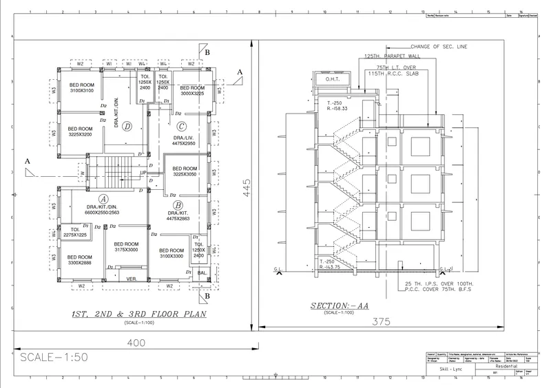
1. Create a layout of the Plan and Section A of the project in Challenges 7, using the template Tutorial-mArch.dwt in a scale as given in the Figure. Use the MV command to create the viewport of the size as shown in Figure. Also, use ATTEDIT command to edit the information in the title block. Use A1 size for the layout. Take a plot.
AIM
To create a layout of the Plan and Section A of the project in Challenges 7, using the template Tutorial-mArch.dwt in a scale as given in the Figure.
INTRODUCTION
A layout is a 2D working environment for creating drawing sheets. The area within a layout is called paper space, where you can add a title block, display scaled views of model space within layout viewports, and create tables, schedules, notes, and dimensions for your drawing.
Viewports allow you to create different views of the objects in your model space and display them on the printed page from different angles and at different scales.
PROCEDURE
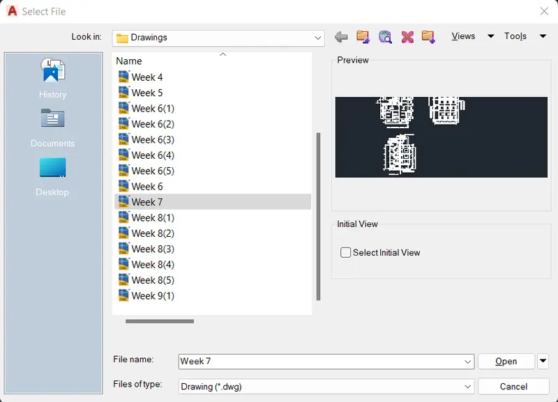
Open the AutoCAD Application and click 'Open files' and select 'Week 7' since reference is taken from week 7 challenges.
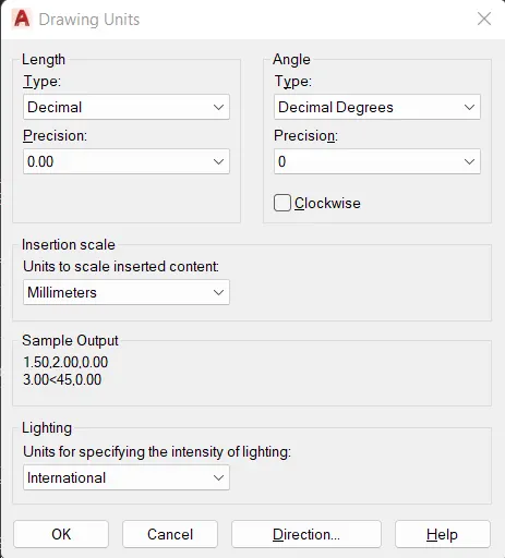
Set the length type in 'Decimal' and precision (0.00), insertion scale to 'Millimeters' in the Drawing Units and press OK. Set limits and zoom all.
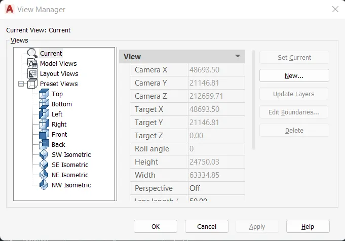
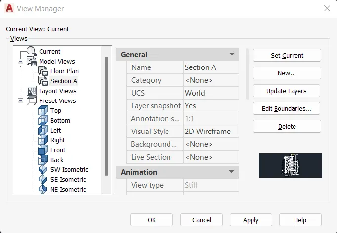
1. Create view of floor plan
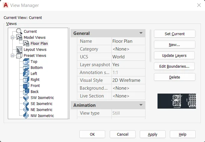
- Type 'V' in the command line and enter to get view manager
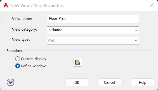
- Click "New" to open new view / shot properties
- View name: "Floor Plan"
- Boundary: Define FLOOR PLAN on screen
- Click OK
- Click OK
- Click "New" to open new view / shot properties
2. Create view of floor plan
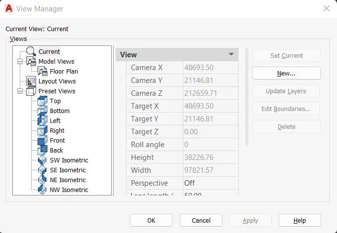
- Type 'V' in the command line and enter to get view manager
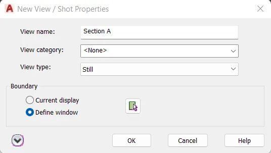
- Click "New" to open new view / shot properties
- View name: "Section A"
- Boundary: Define SECTION A on screen
- Click OK
- Click OK
- Click "New" to open new view / shot properties
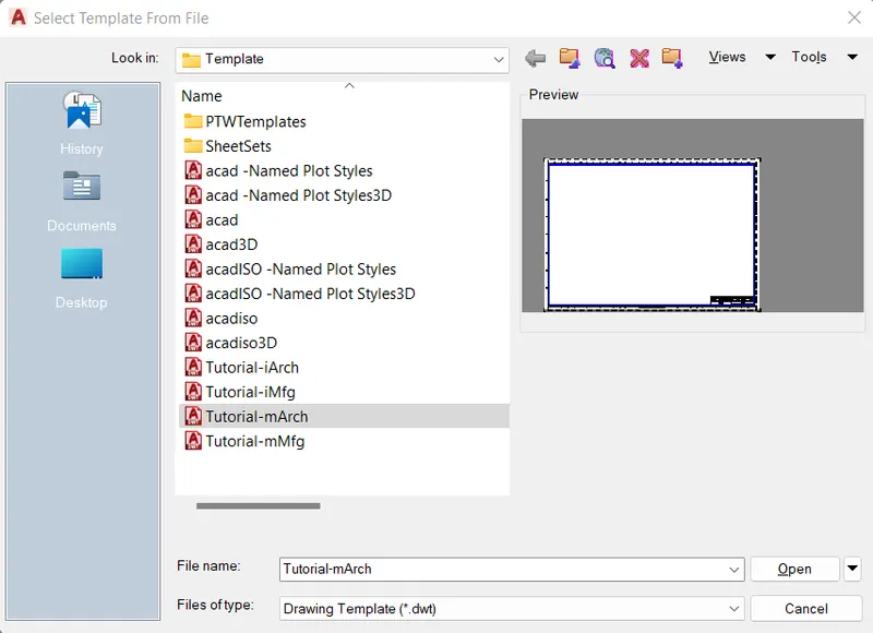
3. Create a new layout with Tutorial-mArch.dwt
- Right click on the layout and select "From Template..."
- Select "Tutorial-mArch" and click Open
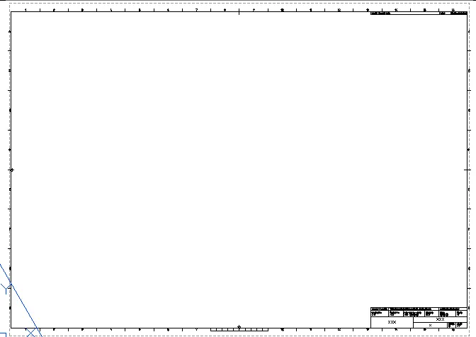
4. Open the views in the layout
- Type "MV" in the command line and enter to get mview
- Type "NA" and enter
- Type "Floor Plan" and enter
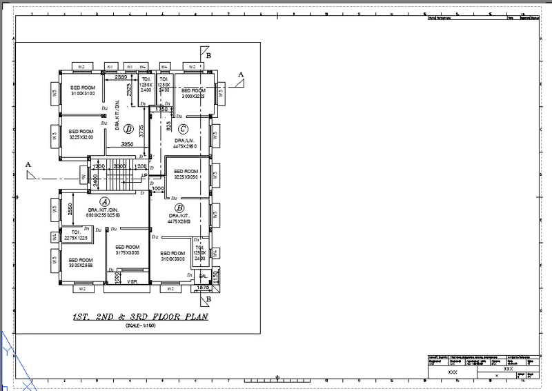
- Place the "Floor Plan" view on the layout
- Adjust the size and scale
- Type 'MS' to adjust the scale
- Type 'PS' to adjust the size
- Size: 400x445
- Scale: 1:50
- Type "MV" in the command line and enter to get mviewType "NA" and enter
- Type "Section A" and enter
- Place the "Section A" view on the layout
- Adjust the size and scale
- Type 'MS' to adjust the scale
- Type 'PS' to adjust the size
- Size: 375x445
- Scale: 1:50
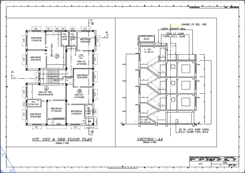
5. Insert dimensions in the layout
- Type 'DIMSTY' in the command line and enter to get dimension style settings
- Dimension Style is created as New
- In Lines, Fixed length extension lines is given as 10mm.
- In Symbols and Arrows, Arrow size is given as 10mm.
- In Text, Text height is given as 10mm
- In Fit, Overall scale is given as 1
- Type 'DIM' in the command line and enter to get dimension line
- Mark all necessary dimensions
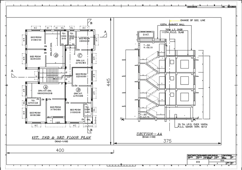
6. Insert texts in the layout
- Type 'DTEXT' in command line and enter to get text tool
- Type necessary details as required
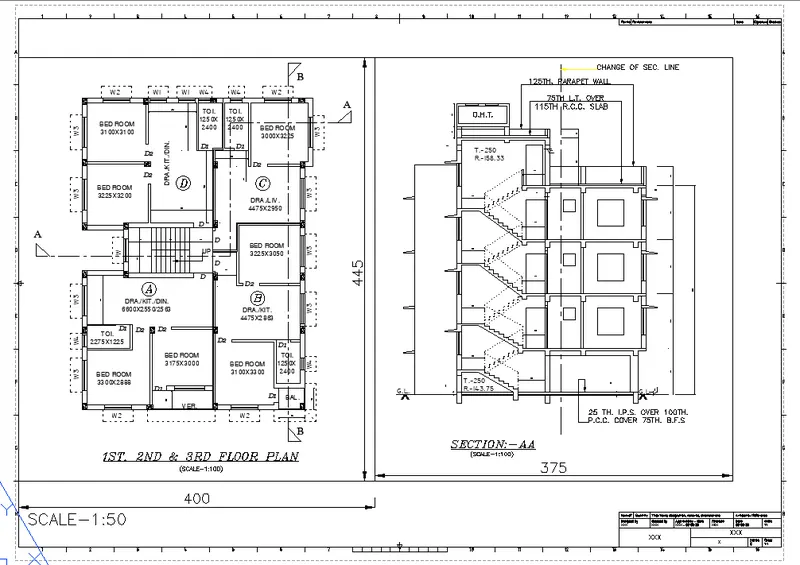
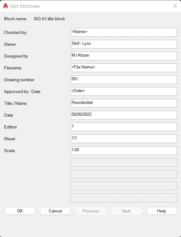
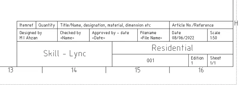
7. Edit the information in the title block
- Type "ATTEDIT" in the command line and enter to get attribute edit
- Select the title block
- Edit the information
8. Take the plot
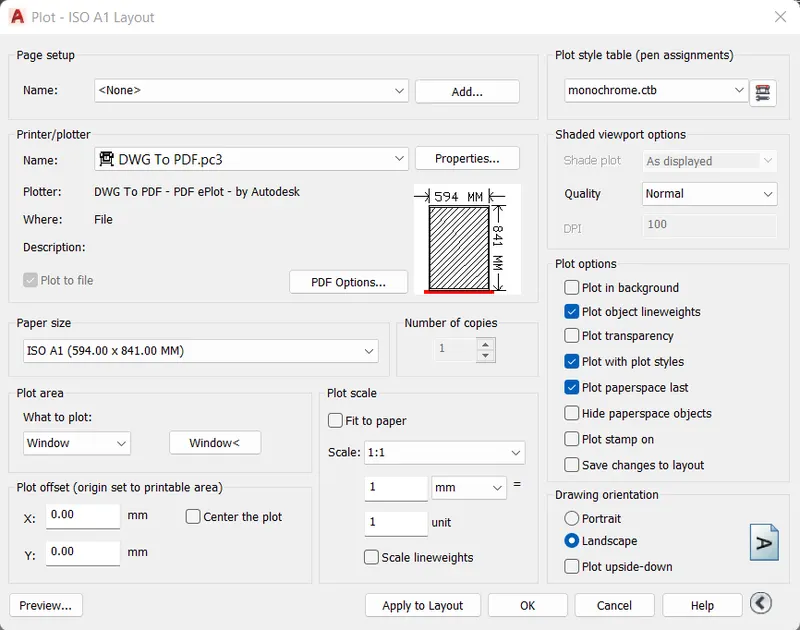
- Right click on the layout tab and click "Plot..." to open plot
- Name: DWG To PDF.pc3
- Paper size: ISO A1 (594.00 x 841.00 MM)
- Plot style table: monochrome.ctb
- Click "Preview" to check
- Click "OK"
RESULT
A layout of the Plan and Section A of the project in Challenges 7 is created using the template Tutorial-mArch.dwt in a scale of 1:50 and taken the plot.
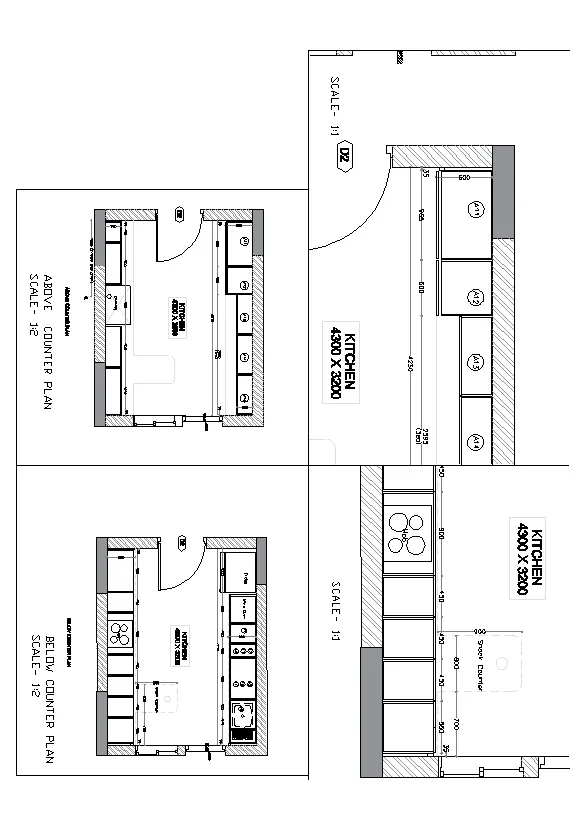
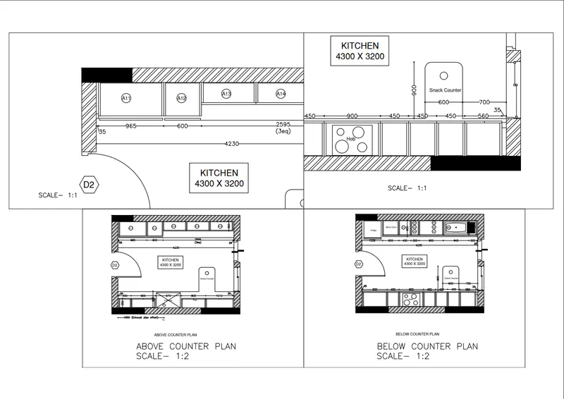
2. Create a layout of the Kitchen drawn in Challenge 9 as shown in Figure. Use the scale as shown in the Figure. Use A4 Size page for the layout. Take a plot.
AIM
To create a layout of the Kitchen drawn in Challenge 9 and scale as shown in Figure.
INTRODUCTION
A layout is a 2D working environment for creating drawing sheets. The area within a layout is called paper space, where you can add a title block, display scaled views of model space within layout viewports, and create tables, schedules, notes, and dimensions for your drawing.
Viewports allow you to create different views of the objects in your model space and display them on the printed page from different angles and at different scales.
PROCEDURE
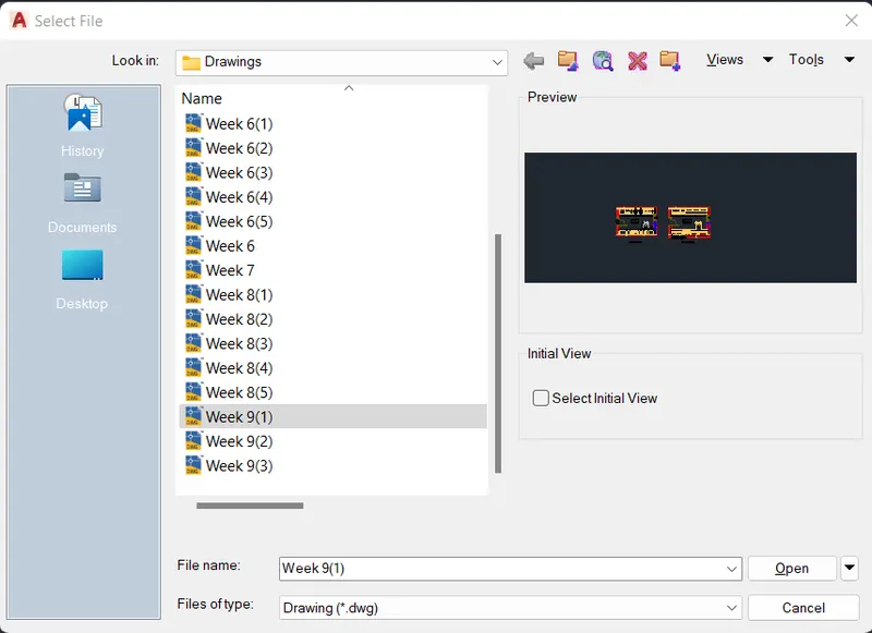
Open the AutoCAD Application and click 'Open files' and select 'Week 9(1)' since reference is taken from week 9 challenges.
Set the length type in 'Decimal' and precision (0.00), insertion scale to 'Millimeters' in the Drawing Units and press OK. Set limits and zoom all.
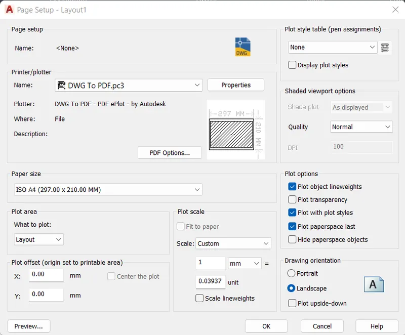
1. Page setup
- Right click on the layout tab and click "Plot..." to open plot
- Paper size: ISO A4 (297.00 x 210.00 MM)
- Click "Preview" to check
- Click "OK"
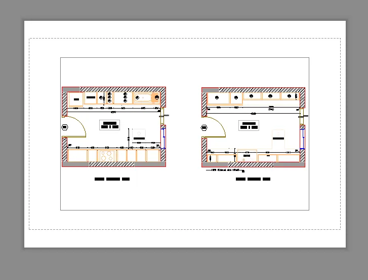
2. Create view inside the layout
- Type 'MS' in the command line and enter to control the mspace
- Adjust the space inside the view port as per the given figure
- Scale: 1:1
- Type 'PS' in the command line and enter to control the pspace
- Adjust the space outside the view port as per the given figure
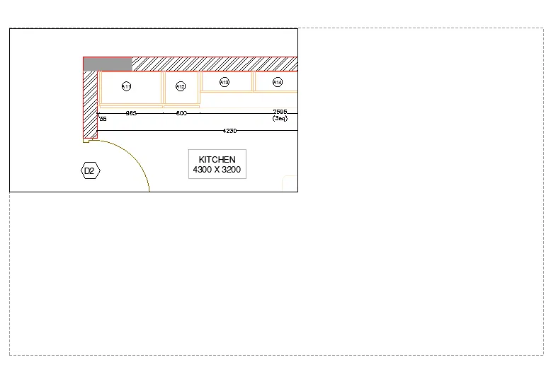
- Type 'MV' in the command line and enter to get the mview
- Type 'P' and enter to get the polygonal
- Draw lines to create a view port as shown in figure.
- Type 'P' and enter to get the polygonal
- Adjust the size scale
- Type 'MS' to adjust the scale
- Type 'PS' to adjust the size
- Scale: 1:1
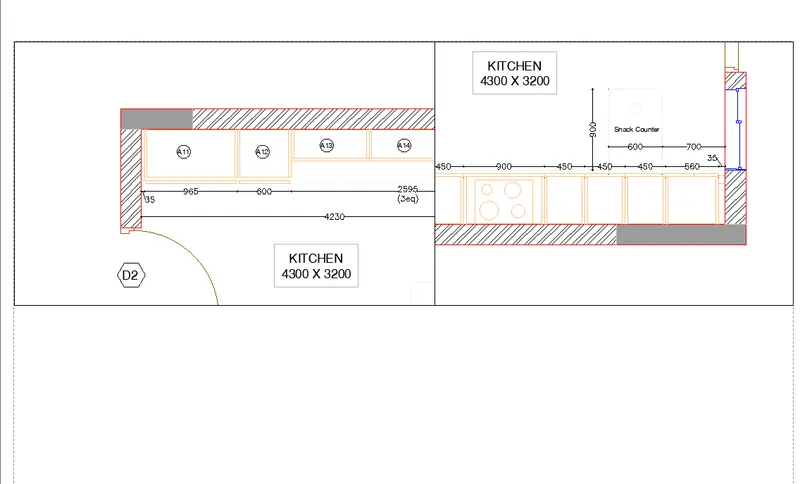
- Type 'MV' in the command line and enter to get the mview
- Type 'P' and enter to get the polygonal
- Draw lines to create a view port as shown in figure.
- Type 'P' and enter to get the polygonal
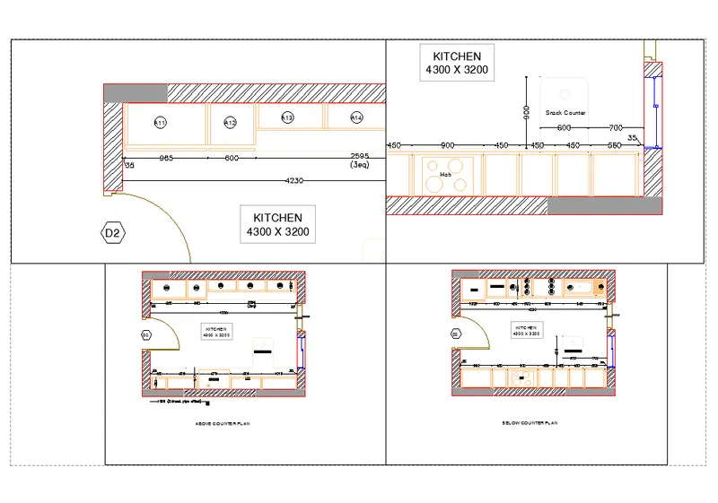
- Adjust the size scale
- Type 'MS' to adjust the scale
- Type 'PS' to adjust the size
- Scale: 1:2
- Repeat the above steps to place another view port
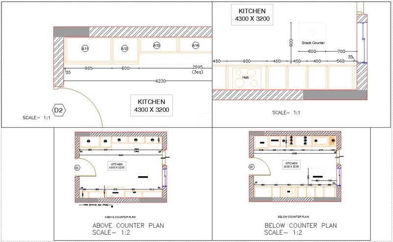
3. Insert texts in the layout
- Type 'DTEXT' in command line and enter to get text tool
- Type necessary details as required
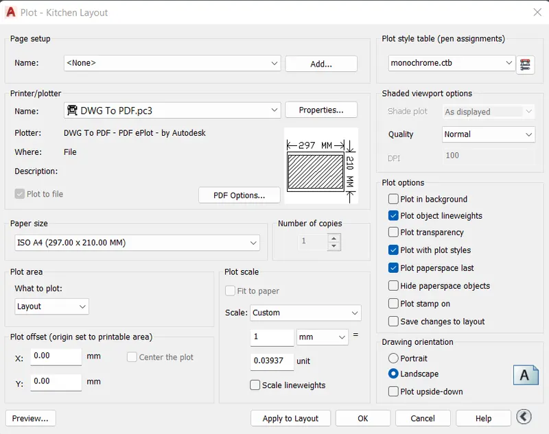
4. Take the plot
- Right click on the layout tab and click "Plot..." to open plot
- Name: DWG To PDF.pc3
- Paper size: ISO A4 (297.00 x 210.00 MM)
- Plot style table: monochrome.ctb
- Click "Preview" to check
- Click "OK"
RESULT
The layout of the Kitchen drawn in Challenge 9 is scaled and created as shown in Figure.
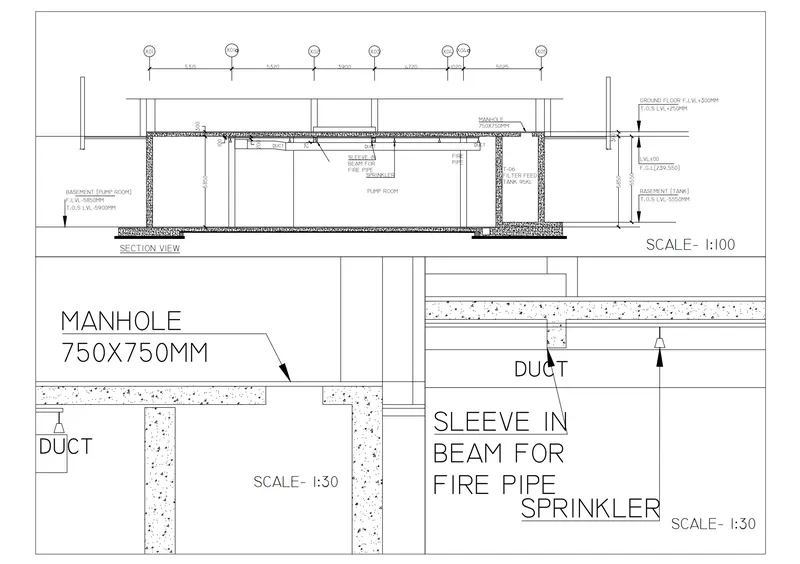
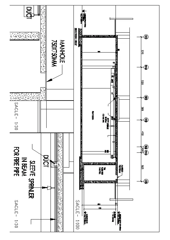
3. Create a layout of the section created in Challenges 9. Use scale as mentioned in the Figure. Use MV command create multiple viewports. Take a plot.
AIM
To create a layout of the section created in Challenges 9 and scale as shown in Figure.
INTRODUCTION
A layout is a 2D working environment for creating drawing sheets. The area within a layout is called paper space, where you can add a title block, display scaled views of model space within layout viewports, and create tables, schedules, notes, and dimensions for your drawing.
Viewports allow you to create different views of the objects in your model space and display them on the printed page from different angles and at different scales.
PROCEDURE
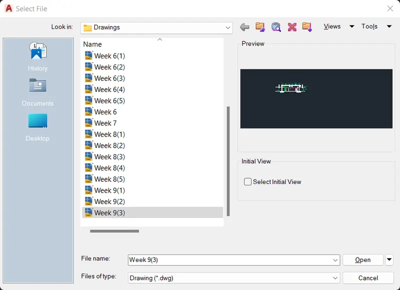
Open the AutoCAD Application and click 'Open files' and select 'Week 9(3)' since reference is taken from week 9 challenges.
Set the length type in 'Decimal' and precision (0.00), insertion scale to 'Millimeters' in the Drawing Units and press OK. Set limits and zoom all.
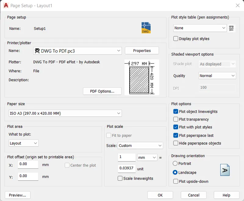
1. Page setup
- Right click on the layout tab and click "Plot..." to open plot
- Paper size: ISO A3 (297.00 x 420.00 MM)
- Click "Preview" to check
- Click "OK"
2. Create view inside the layout
- Type 'MS' in the command line and enter to control the mspace
- Adjust the space inside the view port as per the given figure
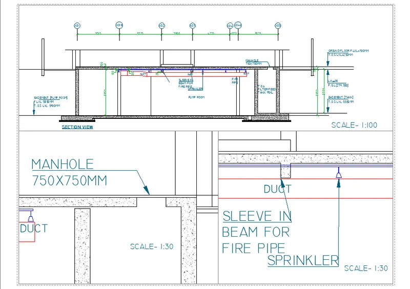
- Scale: 1:100
- Type 'PS' in the command line and enter to control the pspace
- Adjust the space outside the view port as per the given figure
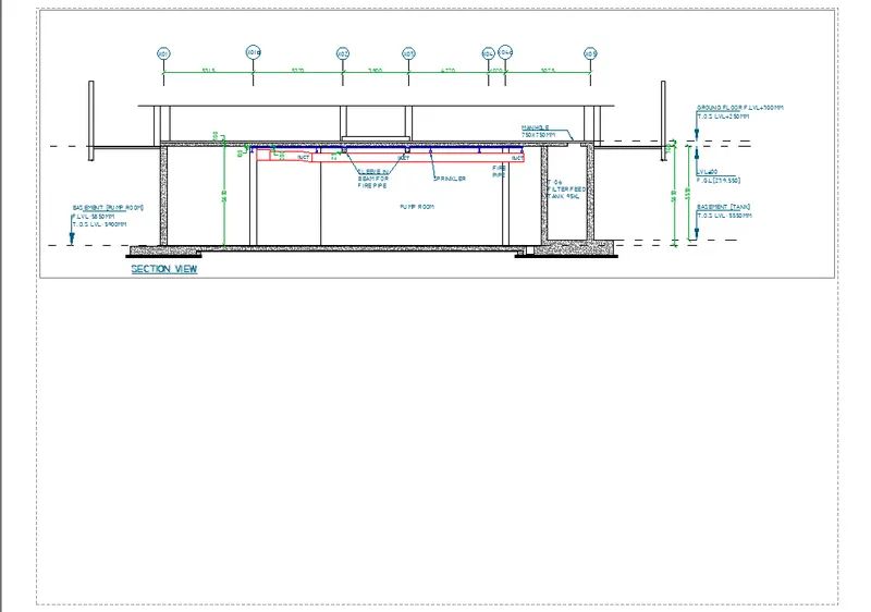
- Type 'MV' in the command line and enter to get the mview
- Type 'P' and enter to get the polygonal
- Draw lines to create a view port as shown in figure.
- Type 'P' and enter to get the polygonal
- Adjust the size scale
- Type 'MS' to adjust the scale
- Type 'PS' to adjust the size
- Scale: 1:30
- Repeat the above steps to place another view port
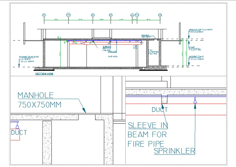
3. Insert texts in the layout
- Type 'DTEXT' in command line and enter to get text tool
- Type necessary details as required
4. Take the plot
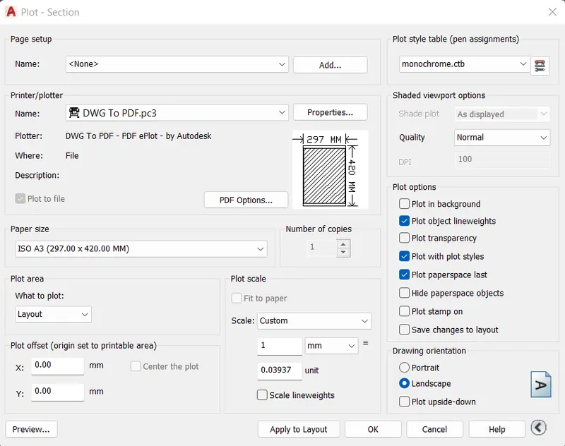
- Right click on the layout tab and click "Plot..." to open plot
- Name: DWG To PDF.pc3
- Paper size: ISO A3 (297.00 x 420.00 MM)
- Plot style table: monochrome.ctb
- Click "Preview" to check
- Click "OK"
RESULT
The layout of the sectionn drawn in Challenge 9 is scaled and created as shown in Figure.