Creation of Multiple viewports, Scaling the drawing and setting in Template in AutoCad
ANS.1.
AIM:-
To create a layout of the plan and section of the project in challenge 7 using the template tutorial march.dwd and also take a plot.
INTRODUCTION :-
Creating the given layout using the commands such as
1.View
2.Pan
3.Plot
4.Xref
5.Layout
6.Viewport
7.Multiple view
8.Model space
9.Paper space
10.Scale
11.Lock
12.Edit
PROCEDURE :-
1. The first step involves to open the AutoCAD and type LIMMAX and enter value 100,100.
2. Then type XREF in the command prompt and their open the dialogue box through which attach the dwg file.
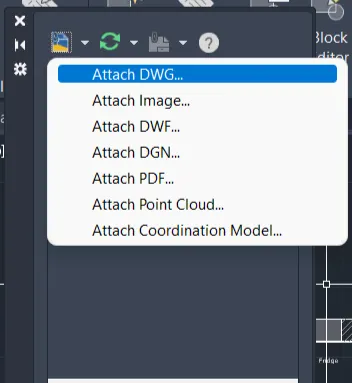
After that rename the layout as layout of plan and section and enter.
Then use the command layout and select a template from that select the tutorial March template which is mentioned in the question.
After that type MS or click on the model space option to view in the model space.
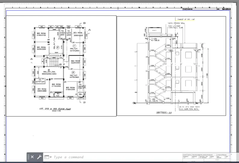
Now to create the viewport As given in the question
Draw rectangle of dimension 400x455 and 375x445 to create the viewport section.
Then enter command MB for multiple view and select the object option then click on the rectangles that are drone and adjust the viewport as per the given scale.
After that log the scale so that the viewport should be logged in the given scale of 1:50
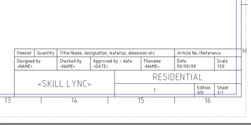
Then to edit the attributes type ATTEDIT in the command prompt and then select the attribute and this type of dialogue box opens.
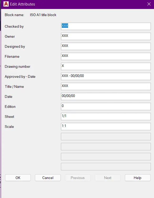
Give proper name to the attribute as per the given figure and then enter.
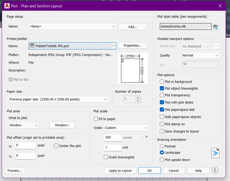
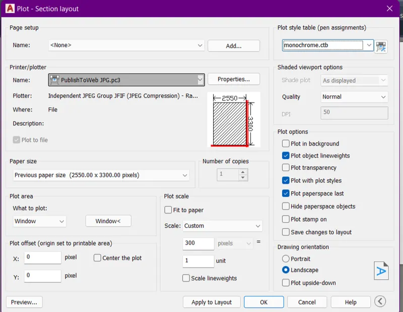
Now to plot the created layout click on the plot option available on the menu bar and then select the JPG option
Also select a proper paper size and plot area that is which area has need to be bloated and Plot style in monochrome.
Plot the drawn layout.
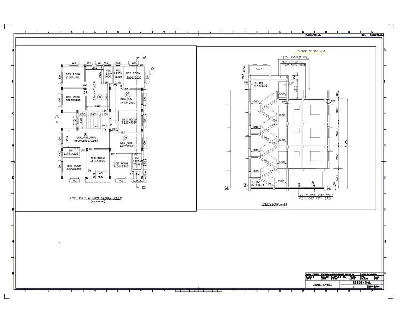
RESULT :
Created Layout of Plan and section is attached below :-
ANS.2.
AIM :-
To create a layout of the kitchen as drawn in the challenge 9 and also to use the scale in the given figure and also use A4 size paper for layout and to take plot.
INTRODUCTION :-
Creating the given layout using the commands such as
1.View
2.Pan
3.Plot
4.Xref
5.Layout
6.Viewport
7.Multiple view
8.Model space
9.Paper space
10.Scale
11.Lock
12.Edit
PROCEDURE :-
1. The first step involves to open the AutoCAD and type LIMMAX and enter value 100,100.
2. Then type XREF in the command prompt and their open the dialogue box through which attach the dwg file.
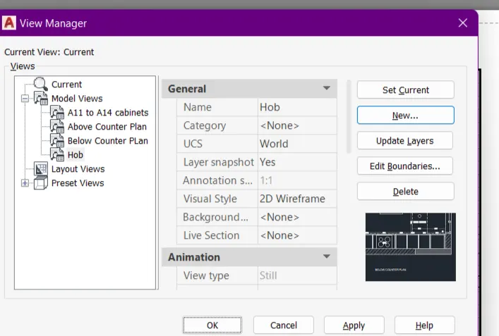
After attaching the file to draw the different views in the layout, open the drawing and use the command View to create different views.
A view manager dialogue box open in which give the give name and select the boundaries and then press ok.
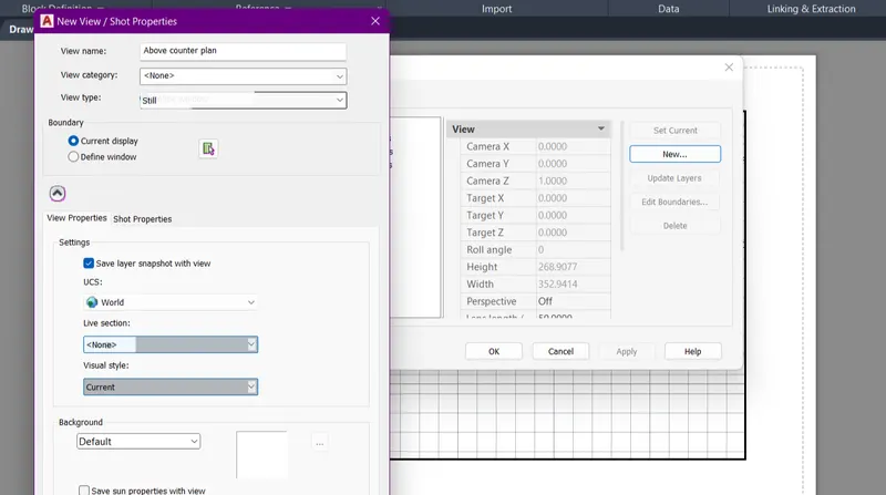
Do the same for the other four views that is
1. Above counter plan
2. Below counter plan
3.Hob
4.A11 to A14 cabinets.
Save them as describe in the above procedure.
Then create the layout with four view ports in A4 sheet
After that open the layout tab and rename it as kitchen layout.
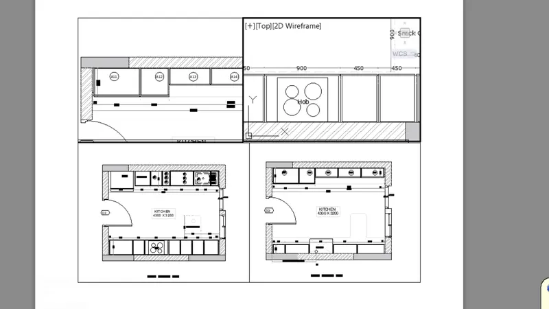
Now type command view in the layout tab and select the required view and lock each viewports .
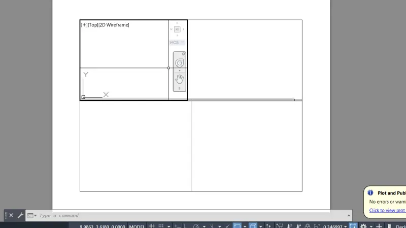 similarly do it for other three viewports also and then write the text has mentioned in the figure using the M text command.
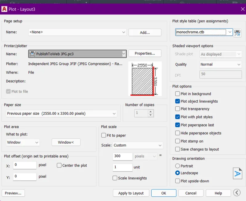
Now to plot the created layout click on the plot option available on the menu bar and then select the JPG option
Also select a proper paper size and plot area that is which area has need to be bloated and Plot style in monochrome.
Plot the drawn layout.
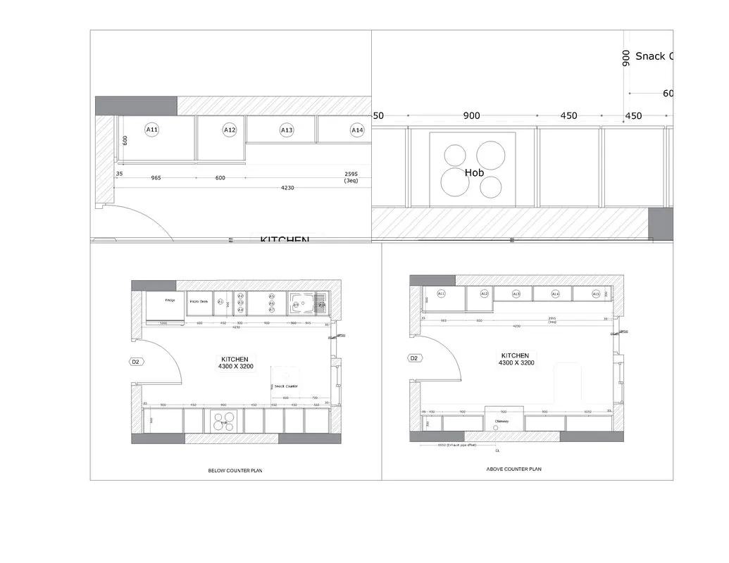
RESULT :-
Created Kitchen layout is attached below :-
ANS.3
AIM:-
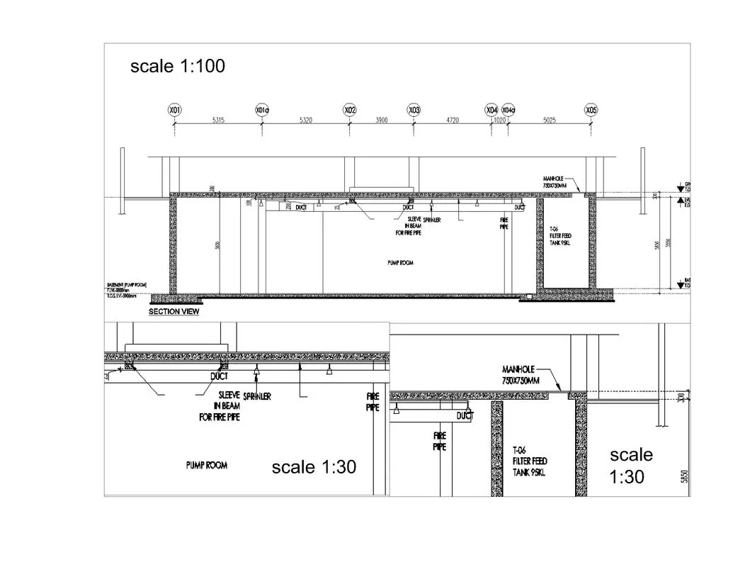
To create the layout of the section that is given the challenge 9 and also to take a plot.
INTRODUCTION :-
Creating the given layout using the commands such as
1.View
2.Pan
3.Plot
4.Xref
5.Layout
6.Viewport
7.Multiple view
8.Model space
9.Paper space
10.Scale
11.Lock
12.Edit
PROCEDURE :-
1. The first step involves to open the AutoCAD and type LIMMAX and enter value 100,100.
2. Then type XREF in the command prompt and their open the dialogue box through which attach the dwg file.
After attaching the file to draw the different views in the layout, open the drawing and use the command View to create different views.
A view manager dialogue box open in which give the give name and select the boundaries and then press ok.
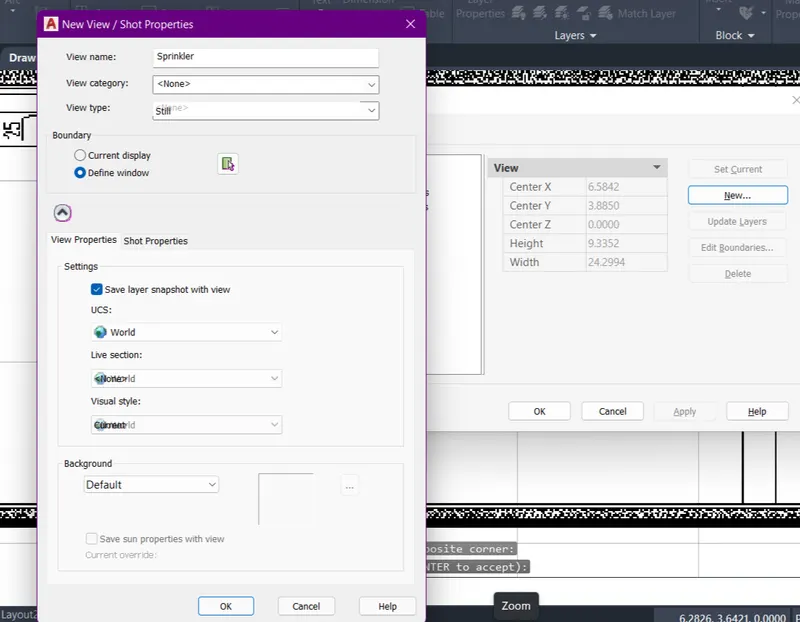
Create two other views that is one is manhole and other is sprinkler view.
Save them by clicking ok.
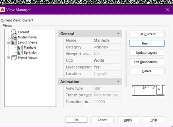
Then use MV Command to create total three viewports as per the given figure
Then use the command MS for model space click on the first view port
Set the scale to one is 1:100 from the toolbar
Then use the pan tool to fit the drawing inside the viewport as per the requirement
To write the text use the M text with height of 10 and then lock the view ports of the writing the text.
Now to plot the created layout click on the plot option available on the menu bar and then select the JPG option
Also select a proper paper size and plot area that is which area has need to be bloated and Plot style in monochrome.
Plot the drawn layout
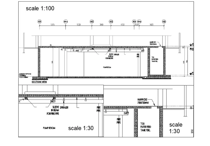
RESULT :-
Created Layout is attached below