Creation of Multiple viewports, Scaling the drawing and setting in Template in AutoCad
Creation of Multiple viewports, Scaling the drawing and setting in Template in AutoCad
1.Create a layout of the Plan and Section A of the project in Challenges 7, using the template Tutorial-mArch.dwt in a scale as given in the Figure. Use the MV command to create the viewport of the size as shown in Figure. Also, use ATTEDIT command to edit the information in the title block. Use A1 size for the layout. Take a plot.
AIM:
To draw the Plan and Section -A layout of challenge 7 as shown in figure using AutoCAD software and explain the procedure step by step to obtain the result.
INTRODUCTION:
AutoCAD is a computer aided design software and drafting software application.
In this project, i have used important commands like,
* Layout - to create new layouts and template. Here, Tutorial mArch- template is used.
* MV - to create multiple Viewports and new viewports.
* ATTEDIT - to edit the attributes in the template block.
* MS,PS - model space and paper space commands to zoom the former and latter separately.
* Scale icon - to scale the viewport as required.
* Page setup manager - to setup the working space as per requirements.
* Plot - To extract the layout as needed and save it in the desktop.
In the next step, the procedure is explained perfectly.
PROCEDURE:
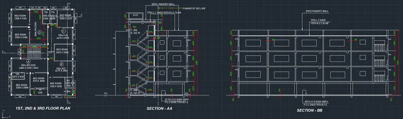
- Open the previously completed drawing of Plan and Section A of the challenge 7.
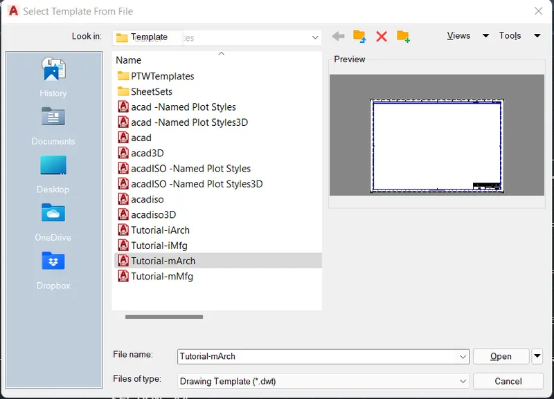
- Using Layout command, select template and choose the Tutorial-mArch template to open.
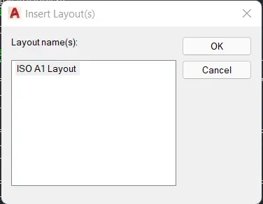
- Select ISO A1 layout and click OK to open.
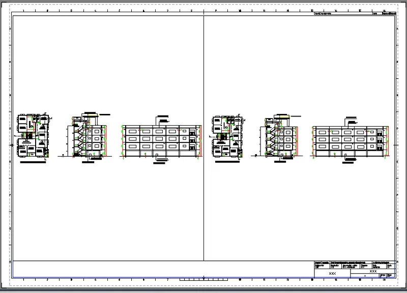
- Now, Using MV command, choose 2 viewports and enter.
- The following image shows the layout with 2 viewports of the model in Tutorial-mArch template.
- Using ATTEDIT command, enter the required data in the space.
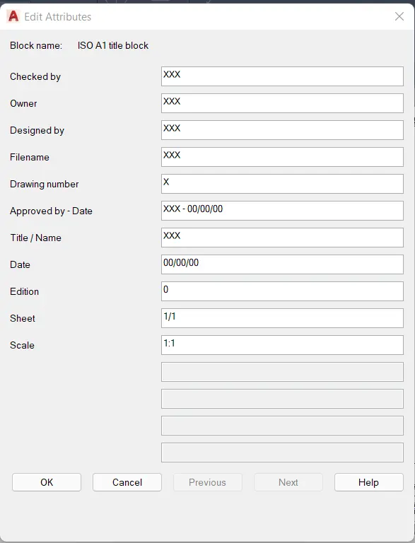
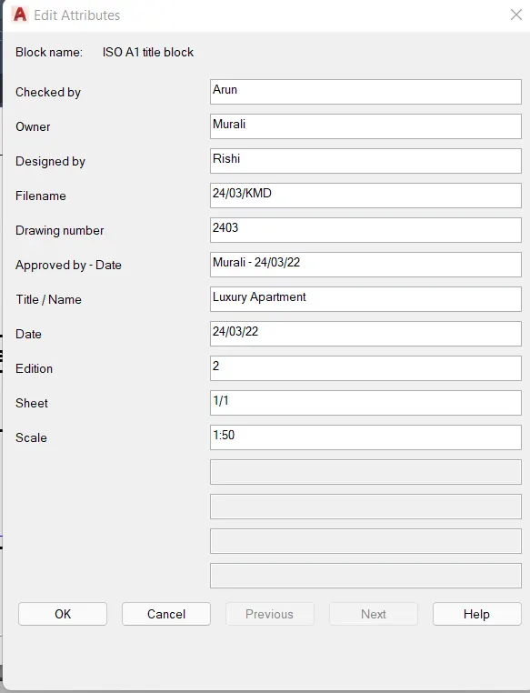
- The following image shows the edited data in the Titleblock present in the tutorial-mArch template.
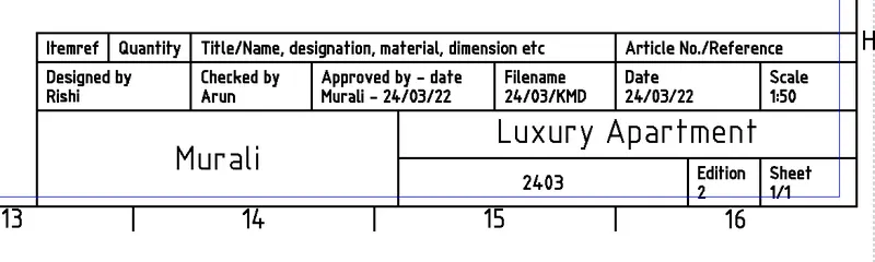
- Using MS command, zoom the viewports to the best possible view.
- Set the paper scale to 1:50
- Using DText & DIM command, enter texts and dimensions.
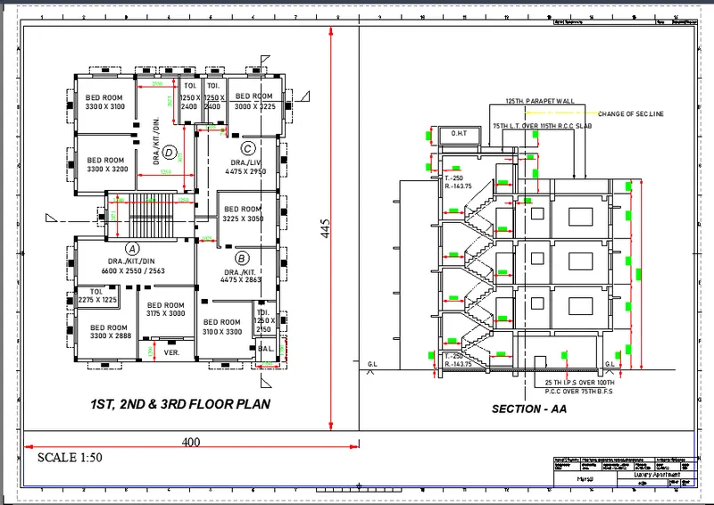
- Using Page setup manager, Set the plot style to monochrome for better viewing.
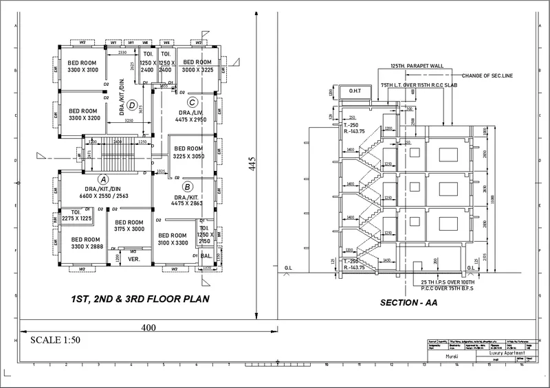
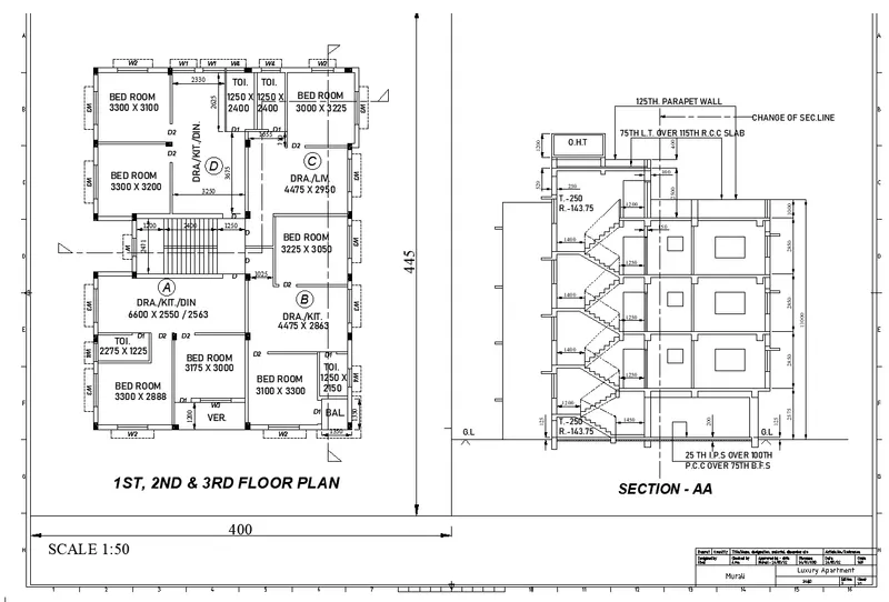
- The following image is the enlarged view of previous image.
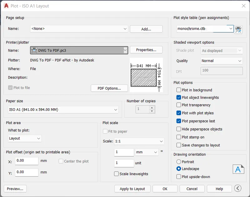
- Using PLOT option, Change the drawing to pdf, choose ISO A1 landscape, Plot style Monochrome and apply and ok.
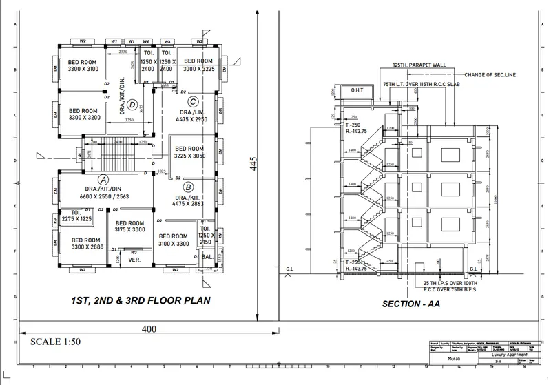
- The following image is the saved Pdf of the layout created in tutorial-mArch template.
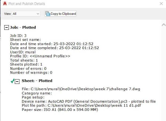
- Upcoming image shows the Plot and publish details.
RESULT:
2. Create a layout of the Kitchen drawn in Challenge 9 as shown in Figure. Use the scale as shown in the Figure. Use A4 Size page for the layout. Take a plot.
AIM:
To draw the Kitchen layout of challenge 9 as shown in figure using AutoCAD software and explain the procedure step by step to obtain the result.
INTRODUCTION:
AutoCAD is a computer aided design software and drafting software application.
In this project, i have used important commands like,
* Layout - to create new layouts and template. Here, Tutorial mArch- template is used.
* MV - to create multiple Viewports and new viewports.
* ATTEDIT - to edit the attributes in the template block.
* MS,PS - model space and paper space commands to zoom the former and latter separately.
* Scale icon - to scale the viewport as required.
* Page setup manager - to setup the working space as per requirements.
* Plot - To extract the layout as needed and save it in the desktop.
In the next step, the procedure is explained perfectly.
PROCEDURE:
- Open the previously completed drawing of Kitchen plan from challenge 9.
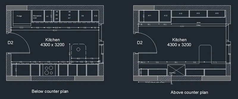
- Set paper size as A4 from the page setup manager.
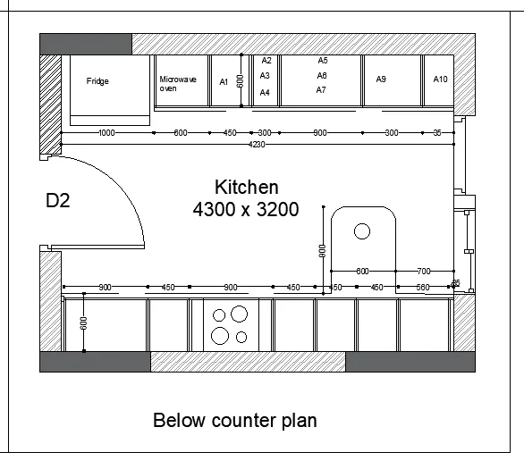
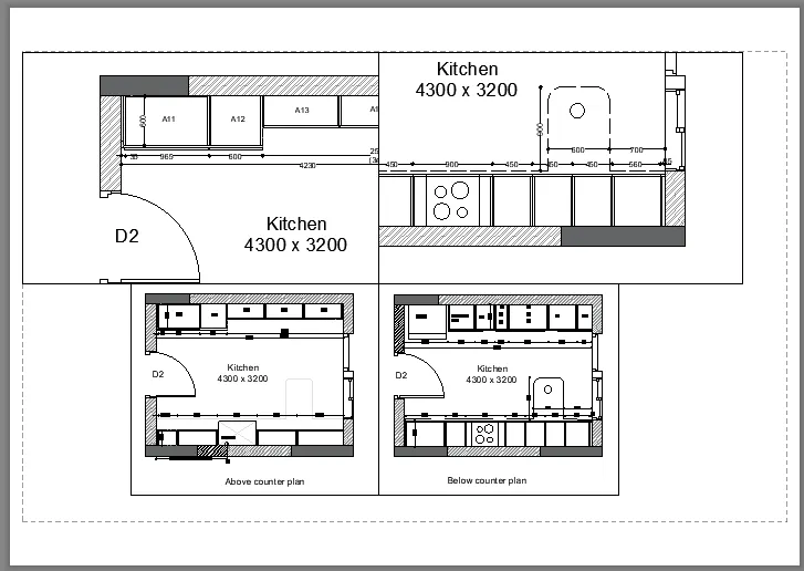
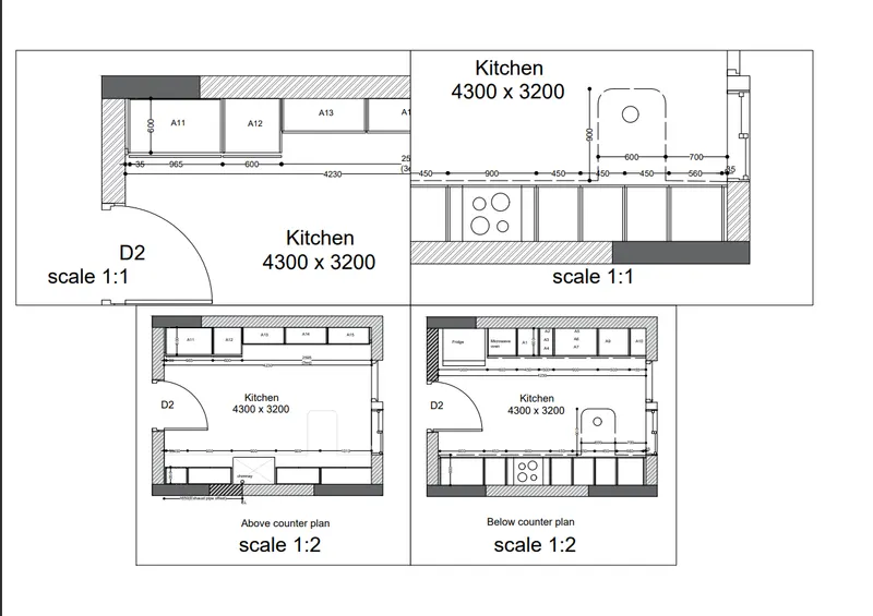
- Using MV command, Choose NEW view and mark the view which is needed from the Above counter plan and enter it in the layout.
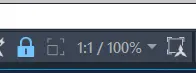
- Using MS command, choose the viewport and set the scale to 1:1 and lock the view port.
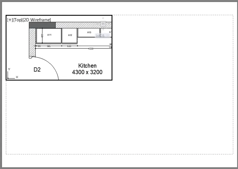
- Again, Using MV command, Choose NEW view and mark the view which is needed from the below counter plan and enter it in the layout.
- Using MS command, choose the viewport and set the scale to 1:1 and lock the view port.
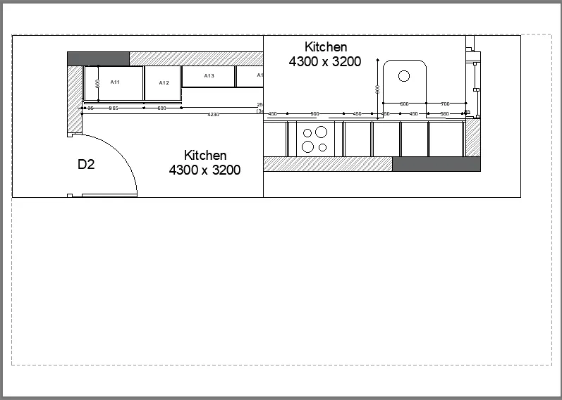
- Using MV command, Choose NEW view and mark the whole Above counter plan and enter it in the layout.
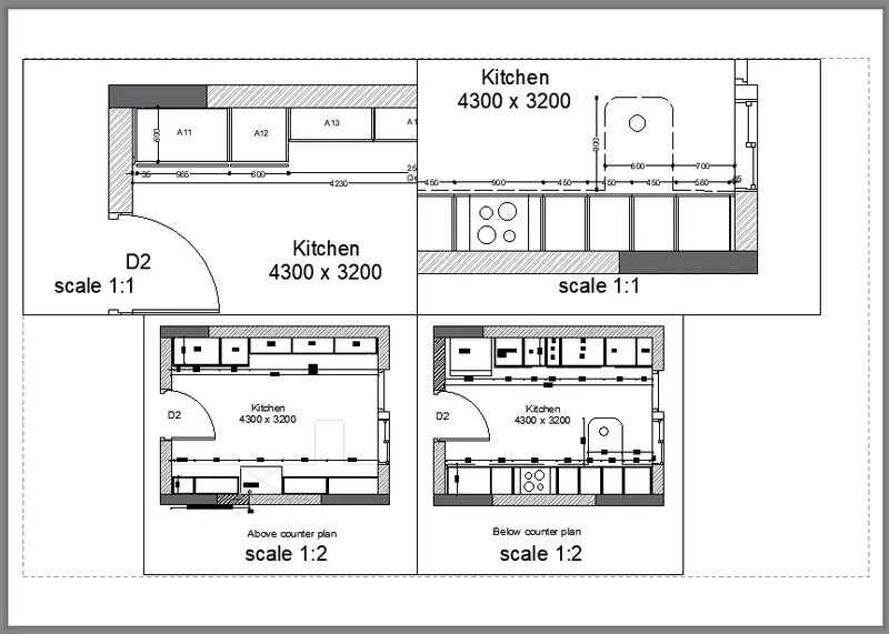
- Using MS command, choose the viewport and set the scale to 1:2 and lock the view port.
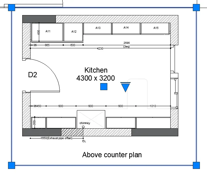
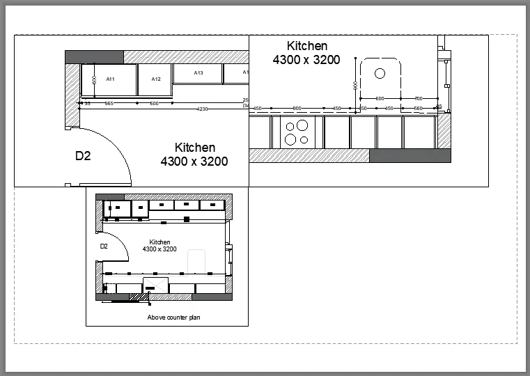
- Using MV command, Choose NEW view and mark the whole Below counter plan and enter it in the layout.
- Using MS command, choose the viewport and set the scale to 1:2 and lock the view port.
- Using DText command, enter the texts at required places.
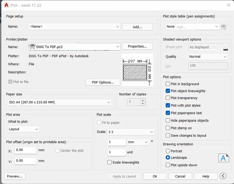
- Using PLOT option, change the drawing to Pdf, choose A4 paper size and enter and save it in the desktop.
- The following image shows the pdf format of the layout created saved in the desktop.
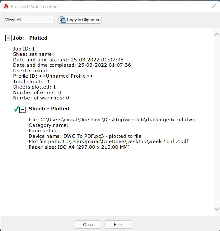
- The PLOT and Publish details are shown here.
RESULT:
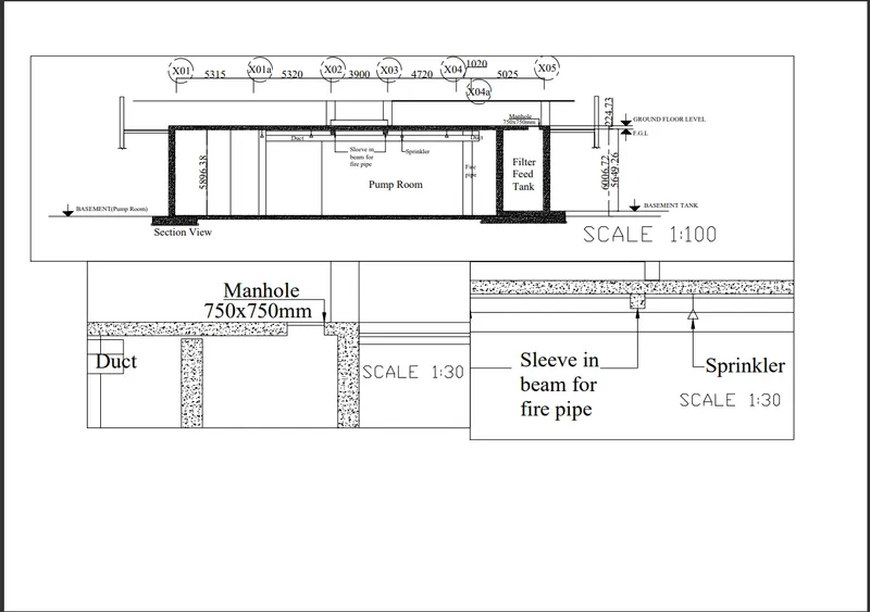
3. Create a layout of the section created in Challenges 9.
Use scale as mentioned in the Figure. Use MV command create multiple viewports. Take a plot.
AIM:
To draw the Industrial section layout of challenge 9 as shown in figure using AutoCAD software and explain the procedure step by step to obtain the result.
INTRODUCTION:
AutoCAD is a computer aided design software and drafting software application.
In this project, i have used important commands like,
* Layout - to create new layouts and template. Here, Tutorial mArch- template is used.
* MV - to create multiple Viewports and new viewports.
* ATTEDIT - to edit the attributes in the template block.
* MS,PS - model space and paper space commands to zoom the former and latter separately.
* Scale icon - to scale the viewport as required.
* Page setup manager - to setup the working space as per requirements.
* Plot - To extract the layout as needed and save it in the desktop.
In the next step, the procedure is explained perfectly.
PROCEDURE:
- Open the previously completed drawing of Industrial Layout from challenge 10.
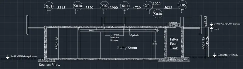
- Set paper size as A2 landscape from the page setup manager.
- Using MV command, Choose NEW view and mark the whole industrial section and enter it in the layout.
- Using MS command, choose the viewport and set the scale to 1:100 and lock the view port.
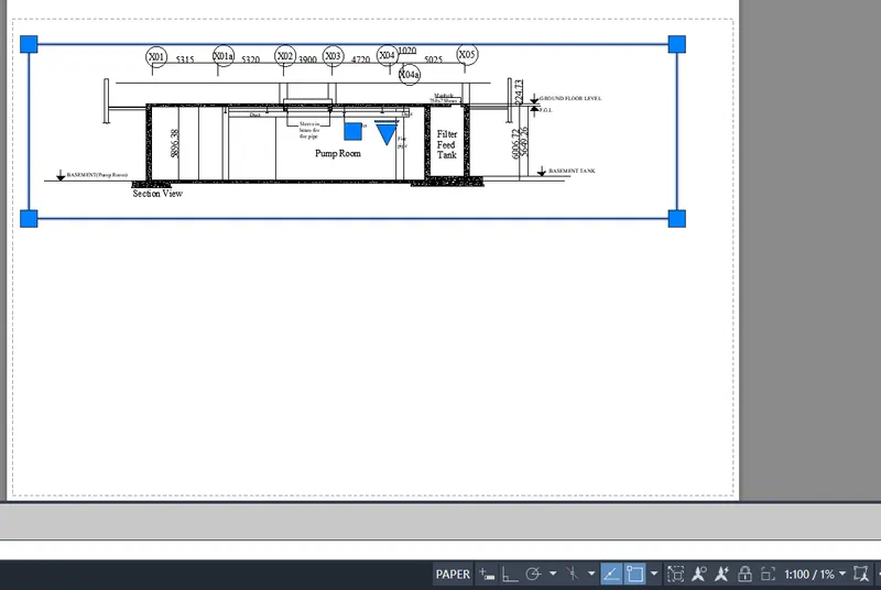
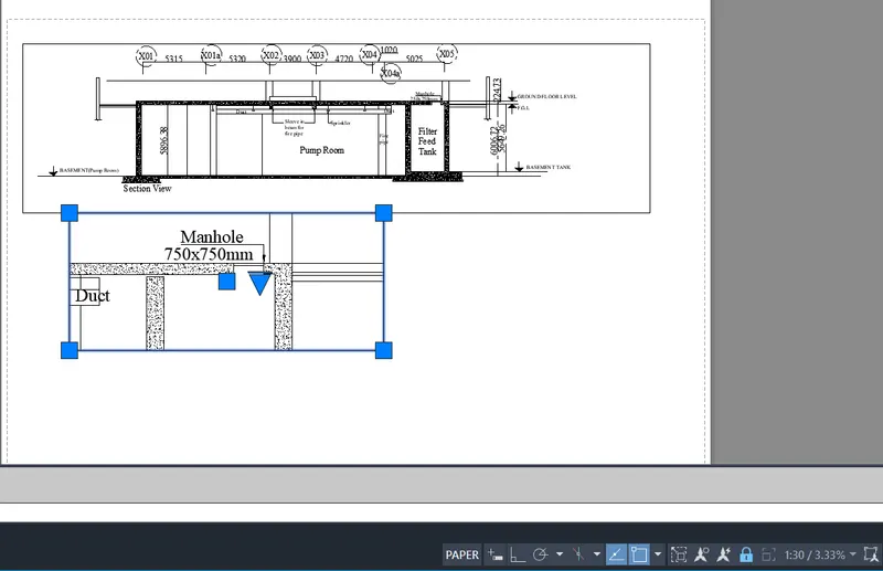
- Using MV command, Choose NEW view and mark the Manhole cover and enter it in the layout.
- Using MS command, choose the viewport and set the scale to 1:30 and lock the view port.
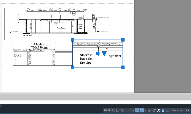
- Using MV command, Choose NEW view and mark the Sleeve in Beam and Sprinkler and enter it in the layout.
- Using MS command, choose the viewport and set the scale to 1:30 and lock the view port.
- using DText command, mention the scales at each viewports.
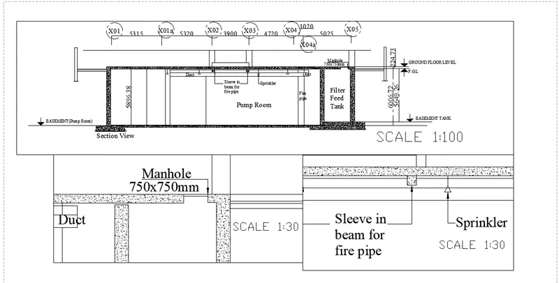
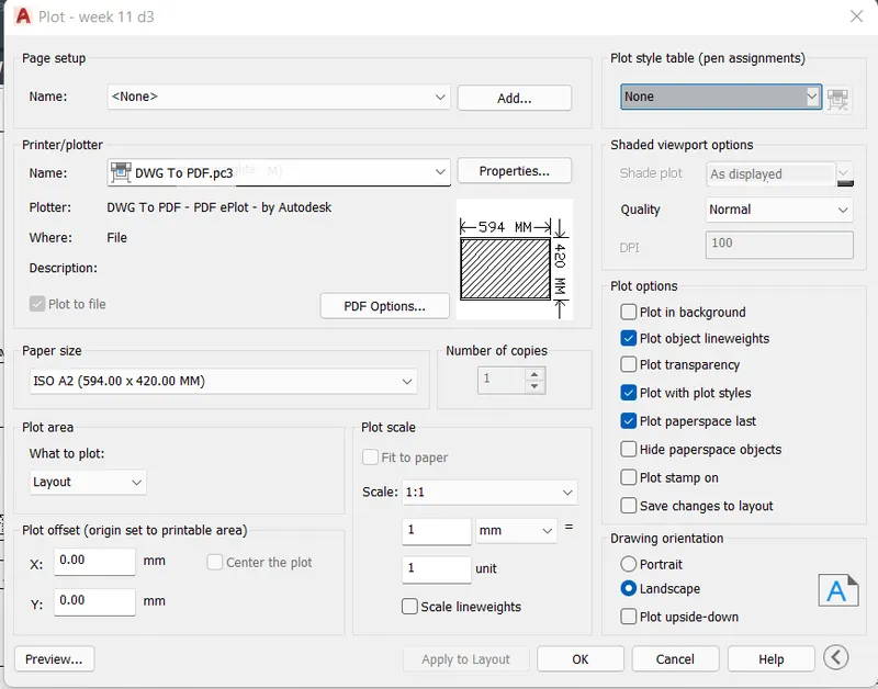
- Using PLOT option, change the drawing to Pdf, choose A2 paper size and enter and save it in the desktop.
- The following image shows the pdf format of the layout created saved in the desktop.
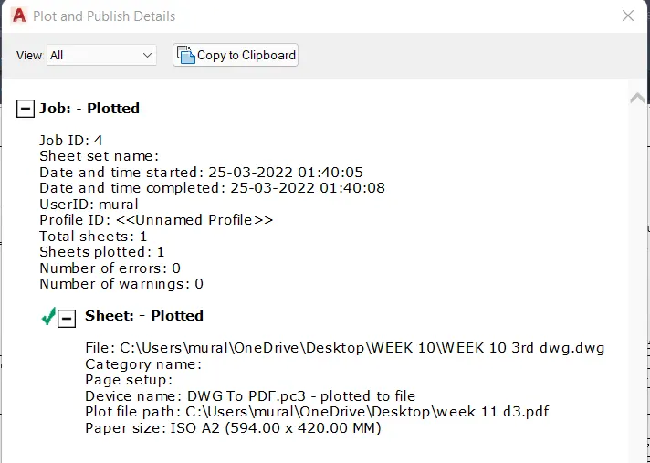
- The PLOT and Publish details are shown here.
RESULT: