Creation of Multiple viewports, Scaling the drawing and setting in Template in AutoCad
Ans 1.
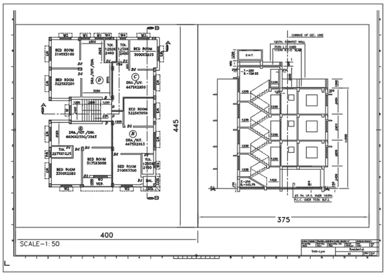
Aim :- Create a layout of the Plan and Section A of the project in Challenges 7, using the template Tutorial-mArch.dwt in a scale as given in Figure in AutoCAD.
Introduction :- Create a layout of the Plan and Section A of the project in Challenges 7, using the template Tutorial-mArch.dwt in a scale as given in the Figure. Use the MV command to create the viewport of the size as shown in Figure. Also, use ATTEDIT command to edit the information in the title block. Use A1 size for the layout. Take a plot.
Procedure :-
- Open the drawing of plan and section which is already drawn in the challenge 7
- In the left corner of an AutoCAD, there is the tab named model, in right side of model there is tab naming layout
- Left click on layout and create new layout from the option from FROM TEMPLATES and select M-arch template select ISO A1 layout
- Then open the new layout to be created
- Rename the layout as plan and section
- Now enter command page setup manager
- A new command page setup will open
- Modify the layout
- Select printer as DWG to pdf
- Select paper size as A1 and then click ok
- Now enter the command as MS in command box and draw rectangle of 440X445 and 375X445
- Now enetr command MV and selct both the rectangles
- Set the scale to 1:50 of the selceted drawing
Result :-
Ans 2.
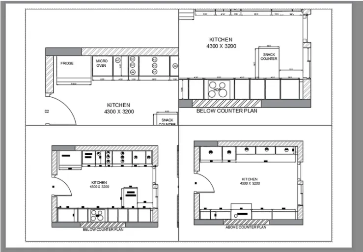
Aim :- Create a layout of the Kitchen drawn in Challenge 9 as shown in Figure AutoCAD.
Introduction :- Create a layout of the Kitchen drawn in Challenge 9 as shown in Figure. Use the scale as shown in the Figure. Use A4 Size page for the layout. Take a plot.
Procedure :-
- Open the drawing of kitchen which is already drawn in challenge 9
- In the left corner of an AutoCAD, there is the tab named model, in right side of model there is tab naming layout
- Left click on layout and create new layout
- Then open the new layout to be created
- Rename the layout as Kitchen layout
- Now enter command page setup manager
- A new command page setup will open
- Modify the layout
- Select printer as DWG to pdf
- Select paper size as A4 and then click ok
- Enter the command VIEWPORTS
- A window will appear on the screen
- Select the viewport type as four equal and enter Ok
- Then specify the first corner point at the left top of the page and drag to another corner point in the right bottom of the page
- Use MS command zoom the view as desired of the below and above counter plan
Result :-
Ans 3.
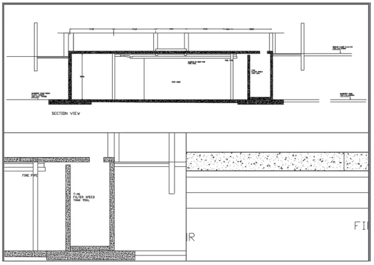
Aim :- Create a Layout of the section drawn in Challenge 9 as shown in Figure AutoCAD.
Introduction :- Create a layout of the section created in Challenges 9.Use scale as mentioned in the Figure. Use MV command create multiple viewports. Take a plot.
Procedure :-
- Open the drawing of INDUSTRIAL SECTION which is already drawn in challenge 9
- In the left corner of an AutoCAD, there is the tab named model, in right side of model there is tab naming layout
- Left click on layout and create new layout
- Then open the new layout to be created
- Rename the layout as section layout
- Now enter command page setup manager
- A new command page setup will open
- Modify the layout
- Select printer as DWG to pdf
- Select paper size as A4 and then click ok
- Enter the command VIEWPORTS
- A window will appear on the screen
- Select the viewport type as three; above and enter Ok
- Then specify the first corner point at the left top of the page and drag to another corner point in the right bottom of the page
- Use MS command zoom the view as desired of the below and above counter plan
Result :-