Creation of Multiple viewports, Scaling the drawing and setting in Template in AutoCad
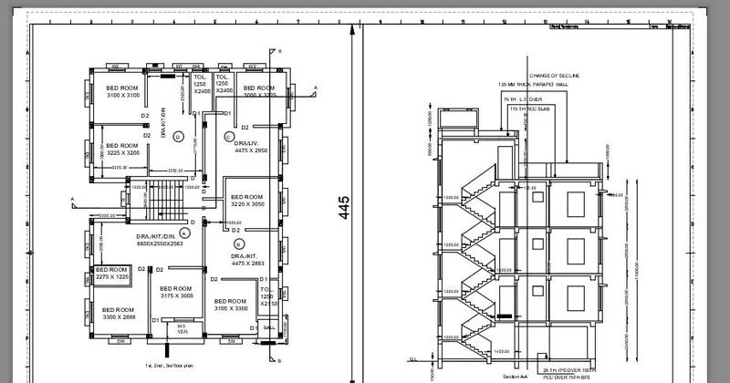
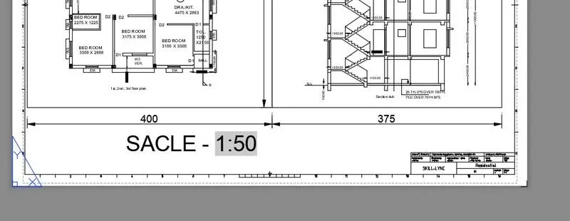
1.Create a layout of the Plan and Section A of the project in Challenges 7, using the template Tutorial-mArch.dwt in a scale as given in the Figure. Use the MV command to create the viewport of the size as shown in Figure. Also, use ATTEDIT command to edit the information in the title block. Use A1 size for the layout. Take a plot.
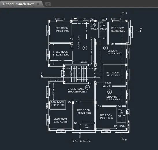
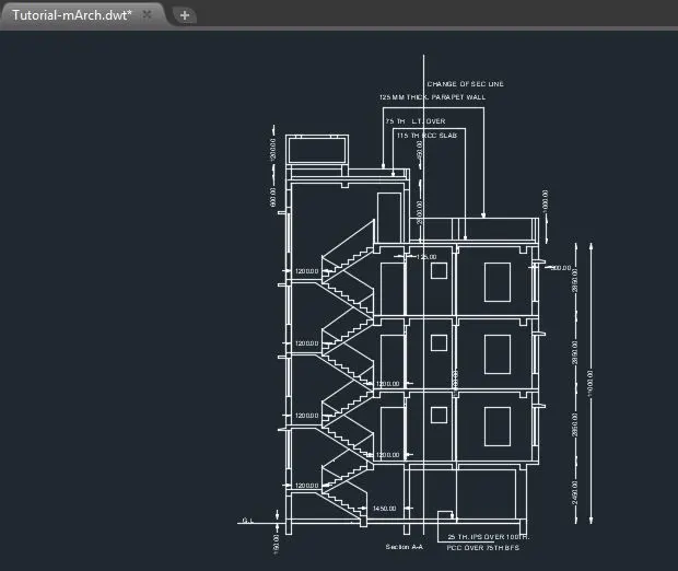
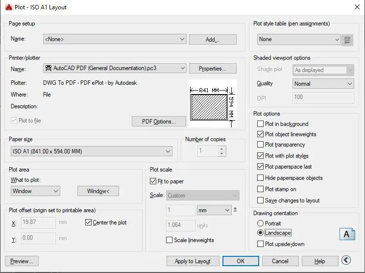
.open autocad and open drawing-file type .dwt and select Tutorial M-arch.dwt file.
.unit command and set decimal and precision 0.00 and unit millimeter.
.d(dimension style manager) command and set decimal and precision 0.00
.using line command , dimension command , copy command,trim command,fillet command,oofset command, multiline text command, block attribute command etc we drawings have been drawn as shown in image.
.go to layout and using MV command , with the help of dimension command we draw two viewports of 400 x 445mm and 375 x 445 mm
.we adust the drawing as shown in viewport at scale of 1:50.
.field command and seclect viewport as object and set custom scale in viewport as given in image.
.to edit the information double click on them and we write as per given in drawing
.for plot press CTRL+P and select single plot
.give Printer name
.select paper size ISO A1(841 MM X 594 MM) and plot area windows and select the required window in layout
.now click on center the paper and fit to paper and in landscape
.click ok for plotting
2.Create a layout of the Kitchen drawn in Challenge 9 as shown in Figure. Use the scale as shown in theFigure. Use A4 Size page for the layout. Take a plot.
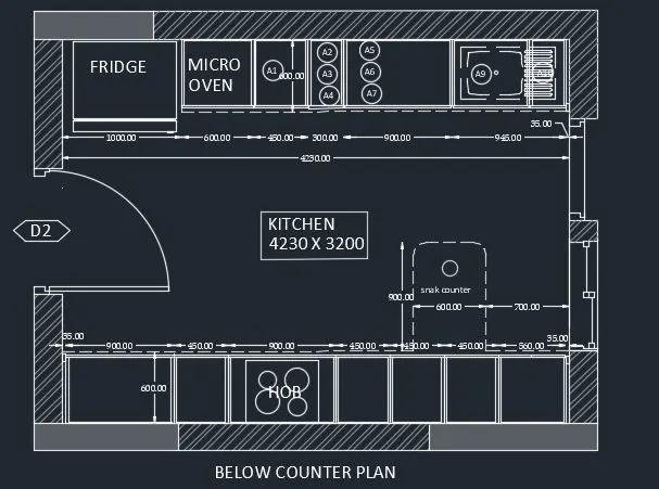
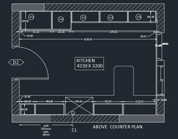
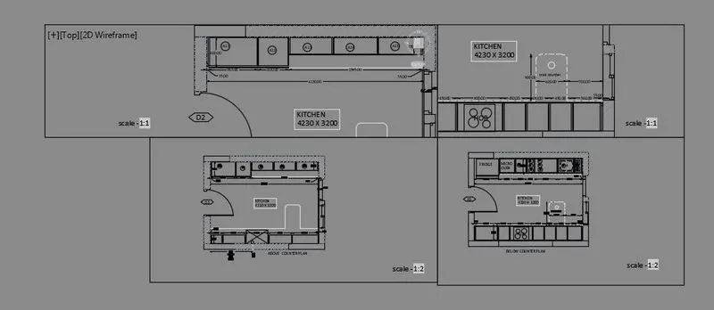
.open auto cad,open new file.
.unit command , type decimal, precision 0.00, and set unit in millimeter.
.command d fot dimension style , in primary set format decimal and precision 0.00.
.using line command, circle command , multiline command, offset command, trim command, we draw kitchen layout as per gievn drawings.
.now go to layout and command MV and draw 4 viewport
.adjust the drawing as dhown in image at scale of 1:1 and 1:2
.command field and select object and custom scale and set scale in viewport as shown.
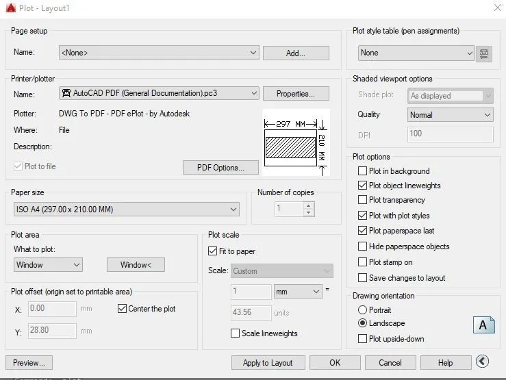
.for plot press CTRL+P and select single plot
.give Printer name
.select paper size ISO A4(297MMX210MM) and plot area windows and select the required window in layout
.now click on center the paper and fit to paper and in landscape
.click ok for plotting
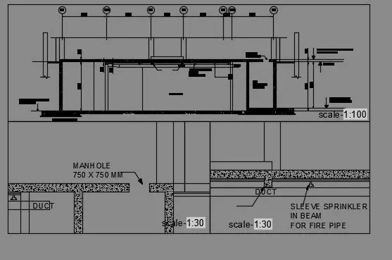
3.Create a layout of the section created in Challenges 9.
Use scale as mentioned in the Figure. Use MV command create multiple viewports. Take a plot.
.open autocad and open new file
.unit command and set decimal and precision 0.00 and unit millimeter.
.d(dimension style manager) command and set precision decimal and 0.00
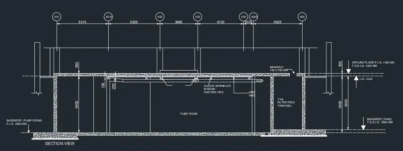
.using line command, circle command and attribute command we draw vertical grid at given dimension
.using line command, offset command, dimension command, trim command, hatch command , mirror command, multiline text command we draw section view as shown in image.
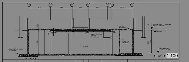
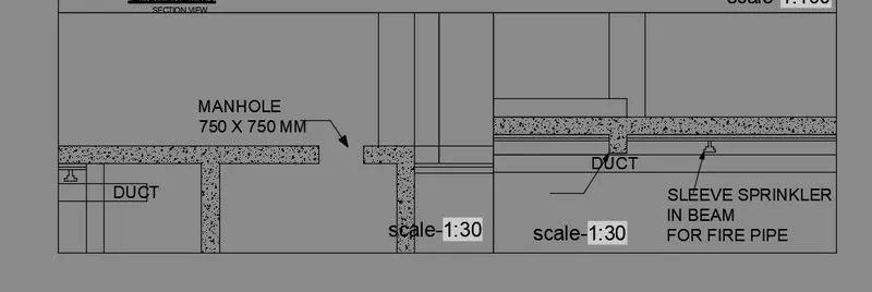
.now go to layout and command MV and draw 3 viewport
.adjust the drawing as dhown in image at scale of 1:100 and 1:30
.command field and select object and custom scale and set scale in viewport as shown.
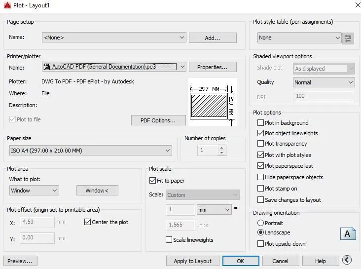
.for plot press CTRL+P and select single plot
.give Printer name
.select paper size ISO A4(297MMX210MM) and plot area windows and select the required window in layout
.now click on center the paper and fit to paper and in landscape
.click ok for plotting