Creation of geometries by Coordinate system methods using AutoCad
1. P1
a) AIM
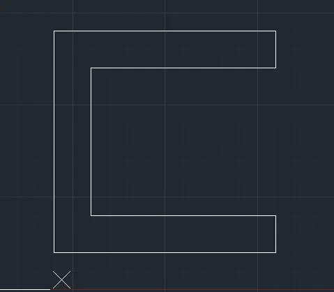
To draw the assignment P1 using all Geometries
b) Tools used
1) Line
c) Procedure
1) Open AutoCad App
2) Click Application toolbar, Click New, Select New template dialog box will Popup, File name "acad", File type "Drawing template ("dwt)".
3) Click Open
4)Click Application Menu, Click save. Save drawing as dialog box Pop up.
5) Name file name as "Challange 1", File type as Autocad 2018 drawing ("dwg").
6) Click save.
7) Go to Menu bar and click "Format", and Units. Set Length type as Architecural, Precision as 0' - 0 1/16"
8) Insertion scale, Units to scale to inserted content as "feet"
9) Lighting, Units for specifying intensity of lighting as " International"
10) Angle type as "Decimal degrees"
11) Click "OK"
12) Go to "formats" and click "Drawing limits"
13) Command Line - LIMITS Lower left corner or [ON/OFF]: Type 0' -0", 0' -0", Press "Enter"
14) Upper right corner <1' -0", 0' -9"> Type: 20'0",20'0"
15) Zoom All
16) Click Line command from "Ribbon"
17) The following Geometries are used for drawing the assignment
a) Absolute coordinate system 2,1
b) Relative coordinate system
c) Distance angle
d) distance by limiting the cursor using ORTHO
e) The points entered at command line are 1) 2,1 2) @6,0 3) @0,1 4) @-5,0 5) ORTHO, enter 4 5)@5,0 6) @ 0,1 7) @-6,0 8) 0,-6