Creating a Residence Layout, Seating plan, Toilet and Utility room plan using AutoCad
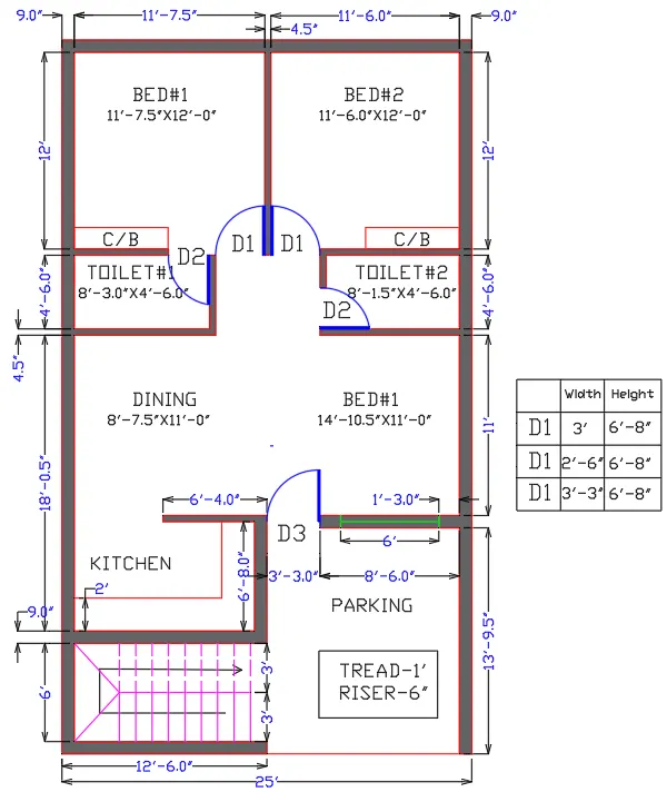
AIM: - To Sketch the layout of a residence using AutoCad.
INTRODUCTION: - The given plan is created using various tools in Autocad like rectangle, polylines, and circle arc modification tools like copy, move, offset, mirror, trim, and fillet, etc.
PROCEDURE: -
Before we start the drawings we need to set up the drawing as Imperial Template and the units into Engineering Units.
Following are the steps in order to set up the drawing as Imperial Template and the units into Engineering Units.
- Go to Application Menu or click CTRL + N (New)
- Click on New from the Application Menu
- A popup menu appears, click on the first tab known as Start from Scratch > Select Imperial
- Now click on the third tab known as Use a Wizard > Go to Advance setup > A Dialog box appears > Select the unit of measurement as Engineering > Press Next > select Angle as Decimal Degrees > Press Next > Select Angle Measure > Press Next > Select Angle Direction > Press Next > Select Area > Click Finish
- Set the page limit by entering Limits in the command tab. The lower left corner is specified as 0'-0.0" and the upper right corner is specified as 100',100'.
- In the Drawing Units dialog box, select 'Engineering' in Type; ' 0'-0.0" ' in Precision; and 'Inches' in Insertion scale.
- Click OK
- Now we are all set to go.
Now,
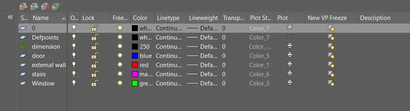
- Click on 'Layer Properties' in the Layer panel on the Ribbon.
- Click on 'New Layer' to create the following layers - Doors, External Wall, Window, Stairs, Dimension, etc.
- Specify different colors for the different layers and then close the Layer Properties Manager dialog box.
Now,
- To begin drawing, select the Ext Wall layer as the default layer in the Layer panel.
- Select the Construction Line tool by entering ‘XLINE’ command in the command tab.
- Draw two lines, one vertical and the other horizontal, both intersecting at a point.
- Press Esc to cancel the XLINE.
- Select the Trim tool by entering ‘TR’ command in the command tab.
- Press ENTER.
- Select Edge option; and click on No Extend.
- Select the extruted lines.
- Press ‘Esc’ to cancel the TRIM command.
Now,
- Select the Offset tool by entering ‘OFFSET’ command in the command tab.
- As thickness of external wall is 9", enter 9.0" as offset distance in the command line.
- Select both the vertical and horizontal lines of the above drawing.
- Specify the next point on the desired side to offset.
- The vertical outer line is offsetted to a distance of 25', which is then offsetted to a distance of 9" as is the thickness of the wall.
- The horizontal outer line is offsetted to a distance of 43'6.5", which is then offsetted to a distance of 9" as is the thickness of the wall.
- Press ‘Esc’ to cancel the OFFSET command.
- The unwanted lines are trimmed off using the TRIM command.
Now,
- Next Offset command is repeated to create all other external walls according to the dimensions given in the plan.
- The bottom inner horizontal line is offsetted to a distance of 6', and the line formed is again offseted to a distace of 9" as is the thickness of the external wall.
- The bottom outer horizontal line is offsetted to a distance of 13'9.5", and the line formed is again offseted to a distace of 9" as is the thickness of the external wall.
- The left ourter vertical line is offsetted to a distance of 12'6", and the line formed is again offseted to a distace of 9" as is the thickness of the external wall
- Then the lines are Trimmed, Erased, Extended and/or Joined to edit the drawing as per requirement.
- Once all the external wall have been created, next the internal wall are drawn.
- Select the Int Wall layer as the default layer in the Layer panel.
- Select the Offset tool by entering ‘OFFSET’ command in the command tab.
- Specify the offset distance, Select the line to offset and click on the direction we need the line in.
- While offsetting, the thickness of the internal walls is specified to be 4.5".
- Press ‘Esc’ to cancel the OFFSET command.
- The new lines drawn are selected and assigned to the Int Wall layer.
- Then the lines are Trimmed, Erased, Extended and/or Joined to edit the drawing as per requirement.
Now,
- For stair case drawing, select the Stairs layer as the default layer in the Layer panel.
- Select the Line tool by entering ‘LINE’ command in the command tab.
- Draw a line of length 6' at a distance of 2'9" from the bottom left inner corner of the plan.
- Press Esc to cancel the LINE command.
- Select the Offset tool by entering ‘OFFSET’ command in the command tab.
- Specify an offset distance of 1', then click on the desired side.
- Next keep selcting and offsetting the lines for 8 more times to form the stairs.
- Press Esc to cancel the OFFSET command.
- Select the Line tool by entering ‘LINE’ command in the command tab.
- Draw a line through the mid-point of the 6' long lines created previously to divide the stairs.
- Press Esc to cancel the LINE command.
- Again select the Line tool by entering ‘LINE’ command in the command tab.
- Draw a line showing the direction of the stairs.
- Press Esc to cancel the LINE command.
- Select the Trim tool by entering ‘TR’ command in the command tab.
- Press ENTER.
- Select Edge option; and click on No Extend.
- Select the unwanted lines.
- Press ‘Esc’ to cancel the TRIM command.
Now,
- To draw doors, select the Doors layer as the default layer in the Layer panel.
- Select the Line tool by entering ‘LINE’ command in the command tab.
- Draw doors at the specified positions.
- Door D3 is created at the entrance with a width of 3'3".
- Press Esc to cancel the LINE command.
- Selet the Arc tool from the ribbon, choose the Start, End, Direction option, then draw an arc to represent the swing of the door by specifying the start, end and direction of the arc as suitable.
- Select the Line tool by entering ‘LINE’ command in the command tab.
- Door D1 is created at the entry of each bedroom with a width of 3'.
- Press Esc to cancel the LINE command.
- Selet the Arc tool from the ribbon, choose the Start, End, Direction option, then draw an arc to represent the swing of the door by specifying the start, end and direction of the arc as suitable.
- Select the Line tool by entering ‘LINE’ command in the command tab.
- Door D2 is created at the entry of each bedroom with a width of 2'6".
- Press Esc to cancel the LINE command.
- Selet the Arc tool from the ribbon, choose the Start, End, Direction option, then draw an arc to represent the swing of the door by specifying the start, end and direction of the arc as suitable.
Now,
- To draw the kitchen slab, select the Kitchen slab layer as the default layer in the Layer panel.
- Select the Offset tool by entering ‘Offset’ command in the command tab.
- Specify the Offset distance as 2'.
- Select the vertical and horizontal inner lines of the kitchen wall.
- Specify the point on side to offset.
- Press Esc to cancel the Offset command.
- Select the Trim tool by entering ‘TR’ command in the command tab.
- Press ENTER.
- Select Edge option; and click on No Extend.
- Select the unwanted lines.
- Press ‘Esc’ to cancel the TRIM command.
- Next, to draw the window, select the Window layer as the default layer in the Layer panel.
- Select the Line tool by entering ‘LINE’ command in the command tab.
- Draw a line of 9" at the inner edge of the bottom living room wall.
- Press Esc to cancel the LINE command.
- Select the Offset tool by entering ‘Offset’ command in the command tab.
- Specify the Offset distance as 1'3".
- Select the vertical line of 9" lenght.
- Specify the point on side to offset.
- Again offset the new line to a distance of 6'.
- Select the vertical line of 9" lenght.
- Specify the point on side to offset.
- Press Esc to cancel the Offset command.
- Erase the first line created.
- Select the Line tool by entering ‘LINE’ command in the command tab.
- Draw a line joining the midpoint of the last two lines to form the window.
- Press Esc to cancel the LINE command.
Now,
- To draw the Cupboards, select the Cupboard layer as the default layer in the Layer panel.
- Select the Rectangle tool by entering ‘REC’ command in the command tab.
- Specify the first corner as the bottom left corner of Bedroom 1, drag the cursor and specify the second point at a distance equal to the length of the common wall between Toilet 1 and Bedroom 1 .
- Select the Offset tool by entering ‘OFFSET’ command in the command tab.
- Specify an offset distance of 1".
- Select the rectangle created earlier, and then click on the inside of the previous rectangle.
- Press Esc to cancel the OFFSET command.
- Select the Copy tool by entering ‘COPY’ command in the command tab.
- Select the rectangles created earlier, press ENTER.
- Specify the base point as the bottom right corner of the rectangle created previously.
- Specif thw second base point as the bottom right corner of Bedroom 2.
- Press Esc to cancel the Copy command
Now, its time for Dimension
- Select the Dimension and Text layer as the default layer in the Layer panel.
- Enter ‘DST’ command in the command tab to open the Dimension Style Manager dialog box.
- Click on the Modify tab.
- Under the Lines option change the colour of the dimension and extension lines.
- Under the Symbols and Arrows option change the Arrow size to 1'.
- Under the Text option change the Text height to 1'.
- Click OK. Then click on Set Current and Close the dialog box.
- Select the Dimension tool by entering 'DIM' in the command line.
- Select the first point and second point of the object to be measured, then drag the dimension line to the desired location. Repeat for all the objects to be measured.
- Enter 'TEXT' command in the command line.
- Specify the start point of text as required.
- Specify height of text as 1'.
- Specify angle of rotation of text as 0.
- Copy the text box to wherever necessary, and then enter the desired data into it.
- Click Enter and press Esc.
- Save the drawing.
RESULT: -
------------------------------------------------------------------------------------------------------------------------------------
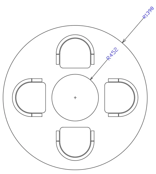
AIM: - To Sketch the seating plan for an outdoor canopy using AutoCad.
INTRODUCTION: - The given plan is created using various tools in Autocad like Line, Circle and Arc tools, etc.
PROCEDURE: -
Before we start the drawings we need to set up the drawing as Metric Template and the units into Decimal Units.
Following are the steps in order to set up the drawing as Metric Template and the units into Decimal Units.
- Go to Application Menu or click CTRL + N (New)
- Click on New from the Application Menu
- A popup menu appears, click on the first tab known as Start from Scratch > Select Metric
- Now click on the third tab known as Use a Wizard > Go to Advance setup > A Dialog box appears > Select the unit of measurement as Decimal > Press Next > select Angle as Decimal Degrees > Press Next > Select Angle Measure > Press Next > Select Angle Direction > Press Next > Select Area > Click Finish
- Set the page limit by entering Limits in the command tab. The lower left corner is specified as 0'-0.0" and the upper right corner is specified as 5000,5000.
- In the Drawing Units dialog box, select 'Metric' in Type; ' 0'-0.0" ' in Precision; and 'mm' in Insertion scale.
- Click OK
- Now we are all set to go.
Now,
- Click on the Circle tool in the Ribbon.
- Select the Centre, Radius option from the drop down list.
- Specify the centre point of circle as 0,0 in the command line.
- Specify Radius of circle as 452.
- Again, click on the Circle tool in the Ribbon.
- Select the Centre, Radius option from the drop down list.
- Specify the centre point of circle as 0,0 in the command line.
- Specify Radius of circle as 1398.
- Select the Line tool.
- Draw one horizontal line and one vertical line to divide the circles into four equal parts
- Press Esc to cancel the Line command.
Now,
- To draw the chair, first select the Rectangle tool by entering ‘RECTANG’ command in the command tab.
- Specify the first point of the rectangle.
- Select Dimensions option in the command line.
- Specify length of rectangle as 350 in the command line.
- Specify width of rectangle as 150 in the command line.
- Move the cursor towards the upward and click ENTER.
- Select the Fillet tool, by entering 'F' in the command tab.
- Selct the Radius option in the command line, and specify a radius of 50.
- Then select the lines to fillet the bottom two corners of the rectangle.
- Click on the Arc tool in the ribbon and select the Start, End, Angle option from the drop down list.
- Draw an arc by specifying the Start and End of the arc as the top corners of the rectangle created previously, and specify the angle as 90.
- Select the Offset tool by entering ‘OFFSET’ command in the command tab.
- Specify an offset distance of 50.
- Select the arc created earlier, and then click on the outside of the arc and repeat again to create the chair handel.
- Press Esc to cancel the OFFSET command.
- Select the Line tool and draw lines to close the ends of the arcs.
- To draw the chair arms, select the Rectangle tool and draw rectangles of length 20 and width 50 at the location of the arm rests
Now,
- Select the chair created in step 3 and Move it to the desired location outside to the edge of the circle of radius 452.
- Click on the Array tool in the Modify panel, then selct the Polar array option.
- Select the chair created as the object to be copied and press ENTER.
- Specify the base point as the centre of the circles.
- Select the Items option in the command line.
- Specify the number of items as 4, and ipress ENTER.
Now, its time for Dimension
- Enter ‘DIMSTY’ command in the command tab to open the Dimension Style Manager dialog box.
- Click on the Modify tab.
- Under the Lines option change the colour of the dimension and extension lines.
- Under the Symbols and Arrows option change the Arrow size to 100.
- Under the Text option change the Text height to 100.
- Click OK. Then click on Set Current and Close the dialog box.
- Select the Dimension tool by entering 'DIMRAD' in the command line.
- Select the object to be measured, then drag the dimension line to the desired location. Repeat for all the objects to be measured.
- Press Esc to cancel the Dimension tool.
- Enter 'TEXT' command in the command line.
- Specify the start point of text as required.
- Specify height of text as 100.
- Specify angle of rotation of text as 0.00.
- Enter the name of the drawing.
- Click Enter and press Esc.
RESULT: -
-----------------------------------------------------------------------------------------------------------------------------------
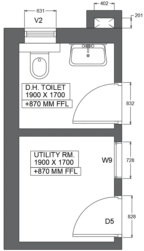
AIM: - To sketch the part plan for the toilets and utilities room using AutoCad.
INTRODUCTION: - The given plan is created using various tools in Autocad like Line, Circle and Arc tools, etc.
PROCEDURE: -
Before we start the drawings we need to set up the drawing as Metric Template and the units into Decimal Units.
Following are the steps in order to set up the drawing as Metric Template and the units into Decimal Units.
- Go to Application Menu or click CTRL + N (New)
- Click on New from the Application Menu
- A popup menu appears, click on the first tab known as Start from Scratch > Select Metric
- Now click on the third tab known as Use a Wizard > Go to Advance setup > A Dialog box appears > Select the unit of measurement as Decimal > Press Next > select Angle as Decimal Degrees > Press Next > Select Angle Measure > Press Next > Select Angle Direction > Press Next > Select Area > Click Finish
- Set the page limit by entering Limits in the command tab. The lower left corner is specified as 0'-0.0" and the upper right corner is specified as 5000,5000.
- In the Drawing Units dialog box, select 'Metric' in Type; ' 0'-0.0" ' in Precision; and 'mm' in Insertion scale.
- Click OK
- Now we are all set to go.
Now,
- To Draw the External Wall select the Construction Line tool by entering ‘XLINE’ command in the command tab.
- Draw two lines, one vertical and the other horizontal, both intersecting at a point.
- Press Esc to cancel the XLINE.
- Select the Offset tool by entering ‘OFFSET’ command in the command tab.
- As thickness of external wall is 300 mm, enter 300 as offset distance in the command line.
- Select both the vertical and horizontal lines of the above drawing.
- Specify the next point on the desired side to offset.
- Next offset the inner horizontal line to a distance of 4250.
- Offset the line again at a distance of 300 to provide the thickness of the wall.
- Press ‘Esc’ to cancel the OFFSET command.
- Select the Trim tool by entering ‘TR’ command in the command tab.
- Press ENTER.
- Select Edge option; and click on No Extend.
- Select the wanted lines.
- Press ‘Esc’ to cancel the TRIM command.
Now,
- To Draw the Internal Wall select the Construction Line tool by entering ‘XLINE’ command in the command tab.
- Draw two lines, one vertical and the other horizontal, both intersecting at a point.
- Press Esc to cancel the XLINE.
- Select the Offset tool by entering ‘OFFSET’ command in the command tab.
- As thickness of external wall is 150 mm, enter 150 as offset distance in the command line ans selct the horizontal internal wall outer line.
- Specify the next point on the desired side to offset.
- Next offset the inner horizontal line to a distance of 2100.
- Then offset the previous line to a distance of 150.
- Offset the Veritcal line again at a distance of 1900.
- Then offset the new line to a distance of 150.
- Press ‘Esc’ to cancel the OFFSET command.
- Select the Trim tool by entering ‘TR’ command in the command tab.
- Press ENTER.
- Select Edge option; and click on No Extend.
- Select the wanted lines.
- Press ‘Esc’ to cancel the TRIM command.
Now,
- To draw doors, select the Line tool by entering ‘LINE’ command in the command tab.
- Draw doors at the specified positions.
- Door D5 is created at the entry location of the Utility Room with a width of 828.
- Press Esc to cancel the LINE command.
- Selet the Arc tool from the ribbon, choose the Start, End, Direction option, then draw an arc to represent the swing of the door by specifying the start, end and direction of the arc as suitable.
- Again select the Line tool by entering ‘LINE’ command in the command tab.
- Draw doors at the specified positions.
- The toilet door is created at the entry location of the Toilet with a width of 832.
- Press Esc to cancel the LINE command.
- Selet the Arc tool from the ribbon, choose the Start, End, Direction option, then draw an arc to represent the swing of the door by specifying the start, end and direction of the arc as suitable.
Now,
- To draw the window, select the Line tool by entering ‘LINE’ command in the command tab.
- Position the window in the utility room as shown in the given diagram.
- Press Esc to cancel the LINE command.
- Select the Offset tool by entering ‘Offset’ command in the command tab.
- Specify the Offset distance as 728 (width of the window).
- Specify the point on side to offset.
- Press Esc to cancel the Offset command.
- Select the Line tool by entering ‘LINE’ command in the command tab.
- Draw a line joining the last two lines to form the window.
- Press Esc to cancel the LINE command.
- Next to draw the ventilator, select the Ventilator layer as the default layer in the Layer panel.
- Select the Line tool by entering ‘LINE’ command in the command tab.
- Position the Ventilator in the toilet as shown in the given diagram.
- Press Esc to cancel the LINE command.
- Select the Offset tool by entering ‘Offset’ command in the command tab.
- Specify the Offset distance as 631 (width of the ventilator).
- Specify the point on side to offset.
- Press Esc to cancel the Offset command.
- Select the Line tool by entering ‘LINE’ command in the command tab.
- Draw lines joining the last two lines to form the section of the ventilator.
- Press Esc to cancel the LINE command.
Now,
- To draw the duct, select the Rectangle tool by entering ‘REC’ command in the command tab.
- Specify the first point as the top right outer corner of the Toilet.
- Select Dimensions option in the command line.
- Specify length of rectangle as 402 in the command line.
- Specify width of rectangle as 401 in the command line.
- Move the cursor towards the left and click ENTER.
- Select the Offset tool by entering ‘OFFSET’ command in the command tab.
- Specify an offset distance of 150.
- Select the rectangle drawn earlier.
- Specify the point on side to offset.
- Press Esc to cancel the Offset command.
Now,
- To draw the Toilet and the Basin.
- Open Design Center by typing DS or by selecting directly from the ribbon tab.
- Find the required fixtures and bring it to the working area by clicking and draging it.
- Now to draw it asp er the drawing we need to do some modifications,
- This is done by using various tools like Line, Circle, etc.
Now, its time for Dimension
- Enter 'DST command in the command tab to open the Dimension Style Manager dialog box.
- Click on Standard
- Click on the Modify tab.
- Select the arrow size as Arrow size to 100. and the Text height to 150.
- Type Dimlinear in the command box for linear dimensions
- Type Dimaligned in the command box for aligned dimensions
- Rest leave everything as it is.
RESULT: -