Creation of geometries by Coordinate system methods using AutoCad
AIM: To create Geometries using cartesian system methods, using line and circle tool.
There are mainly 4 types of cartesian methods
- Absolute Coordinates
- Relative Rectangular Coordinates
- Relative Polar Coordinates
- Direct Distance Entry
P1
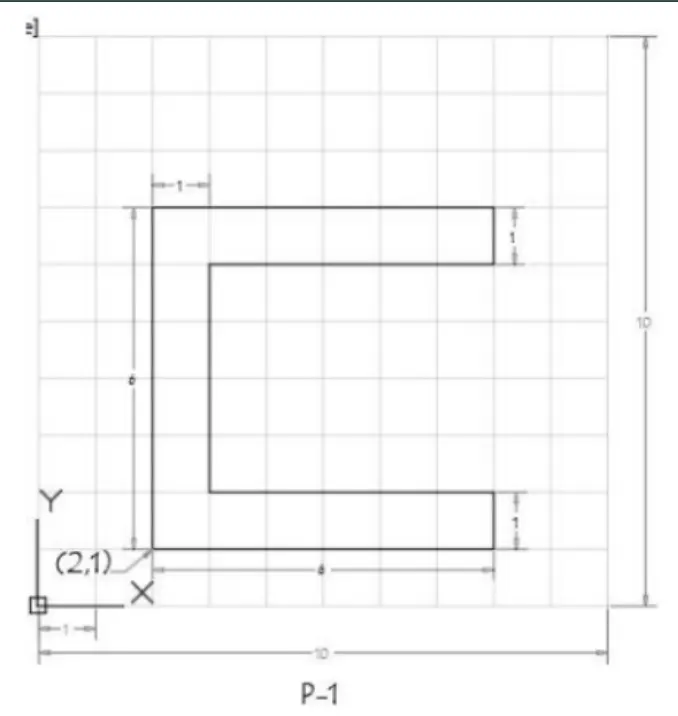
Procedure:
Absolute coordinates system:
- Click on the AutoCad application to run the application
- Type QNEW in the command bar and enter
- Select default setting as Imperial (feet and inches)
- In the default setting, click on use a wizard, and in that advance setting, set the unit as decimal and precision as 0 and press next
- Set angle as decimal degree and precision as 0 then click next
- Set angle measure as east and next step
- Angle direction to be set in Counter-Clockwise direction
- Area to be given as length 10 and width 10
- Finish, then the new workspace appears
- In Command box type LINE, asks to specify the first point
- First point to be given is 2,1. It asks to specify next point simultaneously after each next point entered
- Second point to be given is 8,1
- Third point to be given is 8,2
- Fourth point to given is 8,2
- Fifth point is 3,2
- Sixth point is 3,6
- Seventh point is 8,6
- Eighth point is 8,7
- Ninth point is 2,7
- Type CLOSE or 2,1 in specify next point to complete the geometry.
Relative Rectangular Coordinates:
- Click on AutoCad application to run the application.
- Type QNEW in command bar and enter
- Select default setting as Imperial (feet or inches)
- In the default setting, click on use a wizard, and in that advance setting, set the unit as decimal and precision as 0 and press next
- Set angle as decimal degree and precision as 0 then click next
- Set angle measure as east and next step
- Angle direction to be set in Counter-Clockwise direction
- Area to be given as length 10 and width 10
- Finish, then the new workspace appears
- In Command box type LINE, asks to specify the first point
- First point to be given is 2,1. It asks to specify next point simultaneously after each next point entered
- Type @6,0 (Dx=6, Dy=0)
- Next, type @0,1 (Dx=0, Dy=1)
- Next, type @-5,0 (Dx=5, Dy=0)
- Next, type @0,4 (Dx=0, Dy=4)
- Next, type @5,0 (Dx=5, Dy=0)
- Next, type @0,1 (Dx=0, Dy=1)
- Next, type @-6,0 (Dx=-6, Dy=0)
- Next, type CLOSE or @0,-6 (Dx=0, Dy=-6)
- The Geometry is done.
Relative Polar Coordinates:
- Click on AutoCad application to run the application.
- Type QNEW in command bar and enter
- Select default setting as Imperial (feet or inches)
- In the default setting, click on use a wizard, and in that advance setting, set the unit as decimal and precision as 0 and press next
- Set angle as decimal degree and precision as 0 then click next
- Set angle measure as east and next step
- Angle direction to be set in Counter-Clockwise direction
- Area to be given as length 10 and width 10
- Finish, then the new workspace appears
- In Command box type LINE, asks to specify the first point
- First point to be given is 2,1. It asks to specify next point simultaneously after each next point entered
- Type @6<0 (towards east)
- Next, type @1<90 (towards north)
- Next, type @5<180 (towards west)
- Next, type @4<90 (towards north)
- Next, type @5<0 (towards east)
- Next, type @1<90 (towards north)
- Next, type @6<180 (towards west)
- Next, type CLOSE or @6<270 (towards south)
- The Geometry is completed.
Direct Distance Entry:
- Click on AutoCad application to run the application.
- Type QNEW in command bar and enter
- Select default setting as Imperial (feet or inches)
- In the default setting, click on use a wizard, and in that advance setting, set the unit as decimal and precision as 0 and press next
- Set angle as decimal degree and precision as 0 then click next
- Set angle measure as east and next step
- Angle direction to be set in Counter-Clockwise direction
- Area to be given as length 10 and width 10
- Finish, then the new workspace appears
- In Command box type LINE, asks to specify the first point
- First point to be given is 2,1. It asks to specify next point simultaneously after each next point entered
- Press 6 and keep cursor towards east
- Press 1 and keep cursor towards north
- Press 5 and keep cursor towards west
- Press 4 and keep cursor towards north
- Press 5 and keep cursor towards east
- Press 1 and keep cursor towards north
- Press 6 and keep cursor towards west
- Type CLOSE or press 6 and keep cursor towards south
- The required Geometry is completed.
Result:
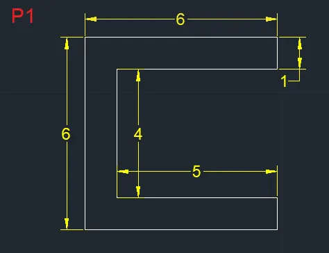
P2
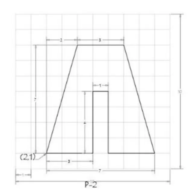
Procedure:
Absolute Coordinates system:
- Click on AutoCad application to run the application.
- Type QNEW in command bar and enter
- Select default setting as Imperial (feet or inches)
- In the default setting, click on use a wizard, and in that advance setting, set the unit as decimal and precision as 0 and press next
- Set angle as decimal degree and precision as 0 then click next
- Set angle measure as east and next step
- Angle direction to be set in Counter-Clockwise direction
- Area to be given as length 10 and width 10
- Finish, then the new workspace appears
- In Command box type LINE, asks to specify the first point
- First point to be given is 2,1. It asks to specify next point simultaneously after each next point entered
- Second point to be given is 5,1
- Third point to be given is 5,5
- Fourth point to be given is 6,5
- Fifth point to be given is 6,1
- Sixth point to be given is 9,1
- Seventh point to be given is 7,8
- Eighth point to be given is 4,8
- Now type CLOSE or give ninth point as 2,1 to get the given geometry.
Relative Rectangular Coordinates:
- Click on AutoCad application to run the application.
- Type QNEW in command bar and enter
- Select default setting as Imperial (feet or inches)
- In the default setting, click on use a wizard, and in that advance setting, set the unit as decimal and precision as 0 and press next
- Set angle as decimal degree and precision as 0 then click next
- Set angle measure as east and next step
- Angle direction to be set in Counter-Clockwise direction
- Area to be given as length 10 and width 10
- Finish, then the new workspace appears
- In Command box type LINE, asks to specify the first point
- First point to be given is 2,1. It asks to specify next point simultaneously after each next point entered
- Next, type @3,0 (Dx=3, Dy=0)
- Next, type @0,4 (Dx=0, Dy=4)
- Next, type @1,0 (Dx=1, Dy=0)
- Next, type @0,-4 (Dx=0, Dy=-4)
- Next, type @3,0 (Dx=3, Dy=0)
- Next, type @-2,7 (Dx=-2, Dy=7)
- Next, type @-3,0 (Dx=3, Dy=0)
- Next, type CLOSE or @-2,-7 (Dx=2, Dy=7) to complete the Geometry.
Relative Polar Coordinates:
- Click on AutoCad application to run the application.
- Type QNEW in command bar and enter
- Select default setting as Imperial (feet or inches)
- In the default setting, click on use a wizard, and in that advance setting, set the unit as decimal and precision as 0 and press next
- Set angle as decimal degree and precision as 0 then click next
- Set angle measure as east and next step
- Angle direction to be set in Counter-Clockwise direction
- Area to be given as length 10 and width 10
- Finish, then the new workspace appears
- In Command box type LINE, asks to specify the first point
- First point to be given is 2,1. It asks to specify next point simultaneously after each next point entered
- Type @3<0 (towards east)
- Next, type @4<90 (towards north)
- Next, type @1<0 (towards east)
- Next, type @4<270 ( towards south)
- Next, type @3<0 (towards east)
- Next, type @7<90 (towards north)
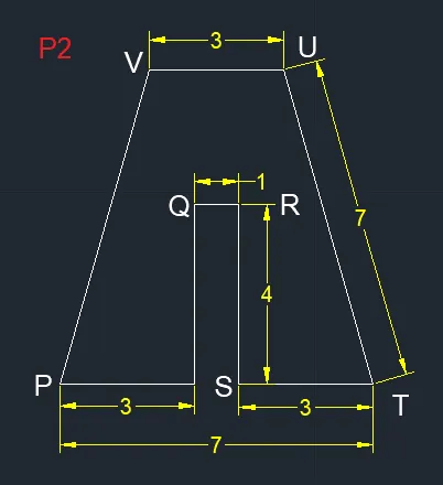
- Next, type @2<180 (join point U and point V through line and erase line UA and line AV)
- After erasing, again take line command and take start point as V.
- Next, type @3<180 ( towards west)
- From W to P close the geometry through line and the required geometry is done.
Direct Distance Entry:
- Click on AutoCad application to run the application.
- Type QNEW in command bar and enter
- Select default setting as Imperial (feet or inches)
- In the default setting, click on use a wizard, and in that advance setting, set the unit as decimal and precision as 0 and press next
- Set angle as decimal degree and precision as 0 then click next
- Set angle measure as east and next step
- Angle direction to be set in Counter-Clockwise direction
- Area to be given as length 10 and width 10
- Finish, then the new workspace appears
- In Command box type LINE, asks to specify the first point
- First point to be given is 2,1. It asks to specify the next point simultaneously after each next point entered
- Press 3 and keep the cursor towards east
- Press 4 and keep the cursor towards north
- Press 1 and keep the cursor towards east
- Press 4 and keep the cursor towards north
- Press 3 and keep the cursor towards east
- Press 7 and keep the cursor towards north
- Press 2 and keep the cursor towards west
- join point U and point V through line and erase line UA and line VA
- Again take line command and start through point V
- Press 3 and keep the cursor towards west
- The required geometry is available.
Result:
P3
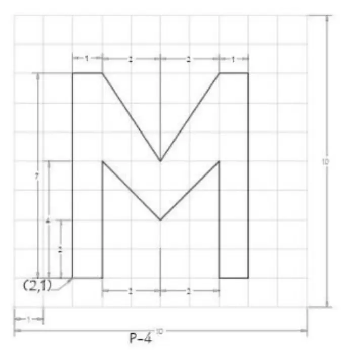
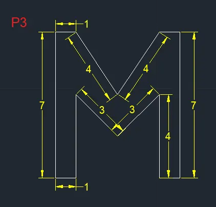
Absolute Coordinate System
Procedure:
- Click on AutoCad application to run the application.
- Type QNEW in command bar and enter
- Select default setting as Imperial (feet or inches)
- In the default setting, click on use a wizard, and in that advance setting, set the unit as decimal and precision as 0 and press next
- Set angle as decimal degree and precision as 0 then click next
- Set angle measure as east and next step
- Angle direction to be set in Counter-Clockwise direction
- Area to be given as length 10 and width 10
- Finish, then the new workspace appears
- In Command box type LINE, asks to specify the first point
- First point to be given is 2,1. It asks to specify the next point simultaneously after each next point entered
- Next point is 3,1
- Next point is 3,5
- Next point is 5,3
- Next point is 7,5
- Next point is 7,1
- Next point is 8,1
- Next point is 8,8
- Next point is 7,8
- Next point is 5,5
- Next point is 3,8
- Next point is 2,8
- Type CLOSE or 2,1 to complete the geometry.
Result:
P4
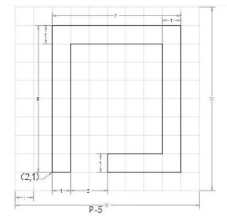
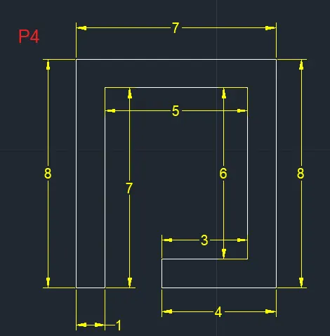
Relative Polar Coordinate System
Procedure:
- Click on AutoCad application to run the application.
- Type QNEW in command bar and enter
- Select default setting as Imperial (feet or inches)
- In the default setting, click on use a wizard, and in that advance setting, set the unit as decimal and precision as 0 and press next
- Set angle as decimal degree and precision as 0 then click next
- Set angle measure as east and next step
- Angle direction to be set in Counter-Clockwise direction
- Area to be given as length 10 and width 10
- Finish, then the new workspace appears
- In Command box type LINE, asks to specify the first point
- First point to be given is 2,1. It asks to specify the next point simultaneously after each next point entered
- Type @8<90
- Next type @7<0
- Next type @8<270
- Next type @4<180
- Next type @1<90
- Next type @3<0
- Next type @6<90
- Next type @5<180
- Next type @7<270
- Type CLOSE or @1<180 to complete the Geometry.
Result:
P5
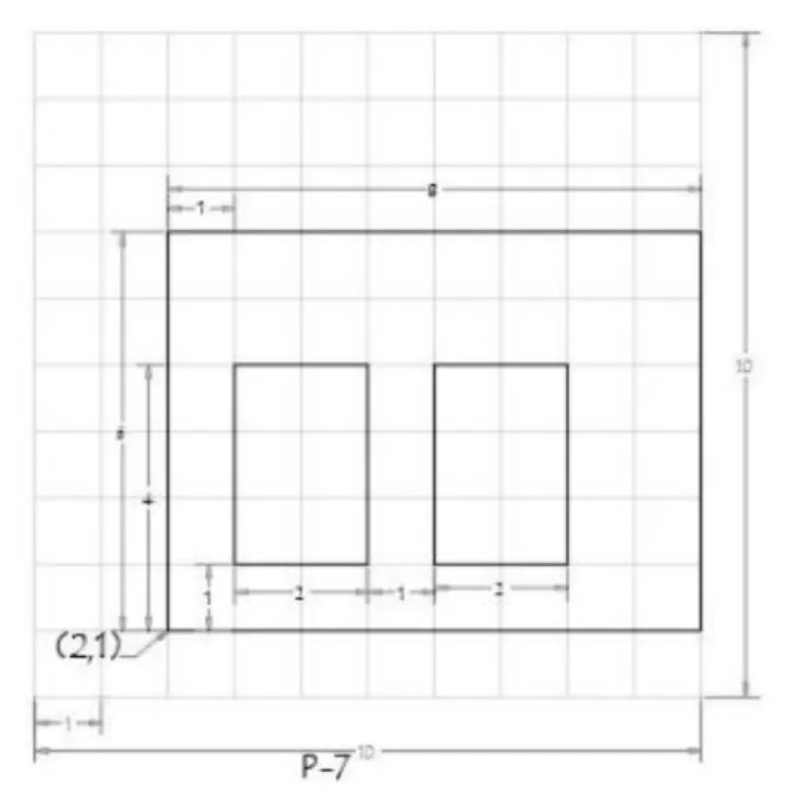
Relative Polar Coordinate System
Procedure:
- Click on AutoCad application to run the application.
- Type QNEW in command bar and enter
- Select default setting as Imperial (feet or inches)
- In the default setting, click on use a wizard, and in that advance setting, set the unit as decimal and precision as 0 and press next
- Set angle as decimal degree and precision as 0 then click next
- Set angle measure as east and next step
- Angle direction to be set in Counter-Clockwise direction
- Area to be given as length 10 and width 10
- Finish, then the new workspace appears
- In Command box type LINE, asks to specify the first point
- First point to be given is 2,1. It asks to specify the next point simultaneously after each next point entered
- Type @8<0
- Next type @6<90
- Next type @8<180
- Type CLOSE
- In Command box type LINE, asks to specify the first point
- Specify first point 3,2
- Next type @2<0
- Next type @3<90
- Next type @2<180
- Type CLOSE
- In Command box type LINE, asks to specify the first point
- Specify first point 6,2
- Next type @2<0
- Next type @3<90
- Next type @2<180
- Type CLOSE to get the desired Geometry.
Result:
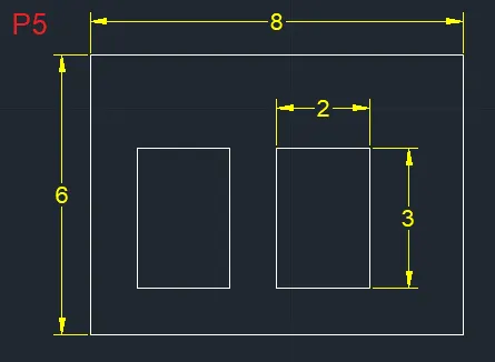
P6
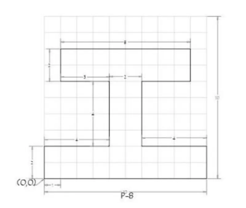
Relative Polar Coordinate System
Procedure:
- Click on AutoCad application to run the application.
- Type QNEW in command bar and enter
- Select default setting as Imperial (feet or inches)
- In the default setting, click on use a wizard, and in that advance setting, set the unit as decimal and precision as 0 and press next
- Set angle as decimal degree and precision as 0 then click next
- Set angle measure as east and next step
- Angle direction to be set in Counter-Clockwise direction
- Area to be given as length 10 and width 10
- Finish, then the new workspace appears
- In Command box type LINE, asks to specify the first point
- First point to be given is 0,0. It asks to specify the next point simultaneously after each next point entered
- Type @2<90
- Next type @4<0
- Next type @4<90
- Next type @3<180
- Next type @2<90
- Next type @6<0
- Next type @2<270
- Next type @3<180
- Next type @4<270
- Next type @4<0
- Next type @2<270
- Type CLOSE or @10<180 to complete the Geometry given.
Result:
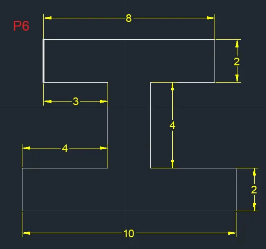
P7
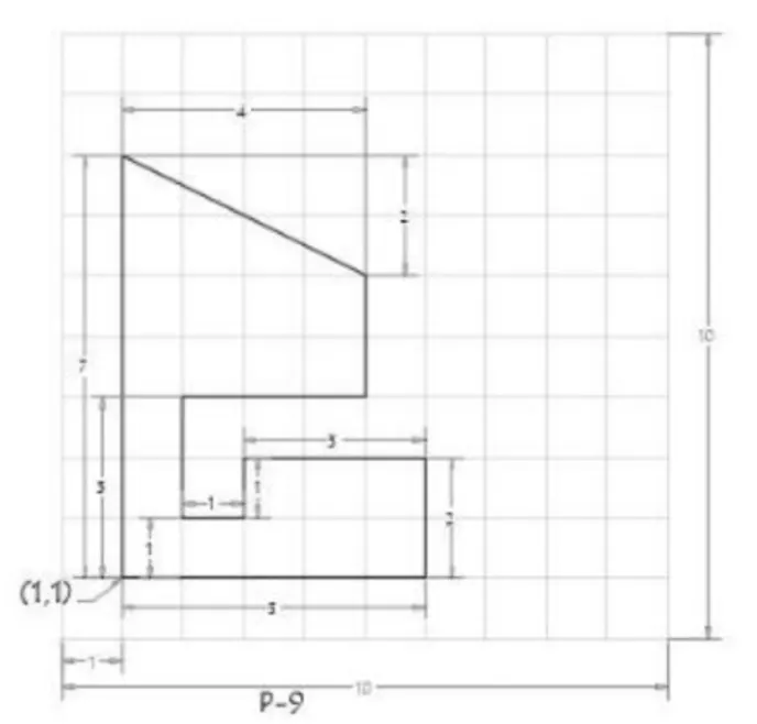
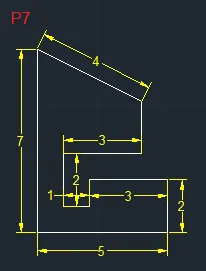
Absolute Coordinate system
Procedure:
- Click on AutoCad application to run the application.
- Type QNEW in command bar and enter
- Select default setting as Imperial (feet or inches)
- In the default setting, click on use a wizard, and in that advance setting, set the unit as decimal and precision as 0 and press next
- Set angle as decimal degree and precision as 0 then click next
- Set angle measure as east and next step
- Angle direction to be set in Counter-Clockwise direction
- Area to be given as length 10 and width 10
- Finish, then the new workspace appears
- In Command box type LINE, asks to specify the first point
- First point to be given is 1,1. It asks to specify next point simultaneously after each next point entered
- Specify point 6,1
- Next, specify point 6,3
- Next, specify point 3,3
- Next, specify point 3,2
- Next, specify point 2,2
- Next, specify point 2,4
- Next, specify point 5,4
- Next, specify point 5,6
- Next, specify point 1,8
- Now type CLOSE or specify point 1,1 to complete the given Geometry.
Result:
P8
Relative Polar Coordinate System
Procedure:
- Click on AutoCad application to run the application.
- Type QNEW in command bar and enter
- Select default setting as Imperial (feet or inches)
- In the default setting, click on use a wizard, and in that advance setting, set the unit as decimal and precision as 0 and press next
- Set angle as decimal degree and precision as 0 then click next
- Set angle measure as east and next step
- Angle direction to be set in Counter-Clockwise direction
- Area to be given as length 10 and width 10
- Finish, then the new workspace appears
- In Command box type LINE, asks to specify the first point
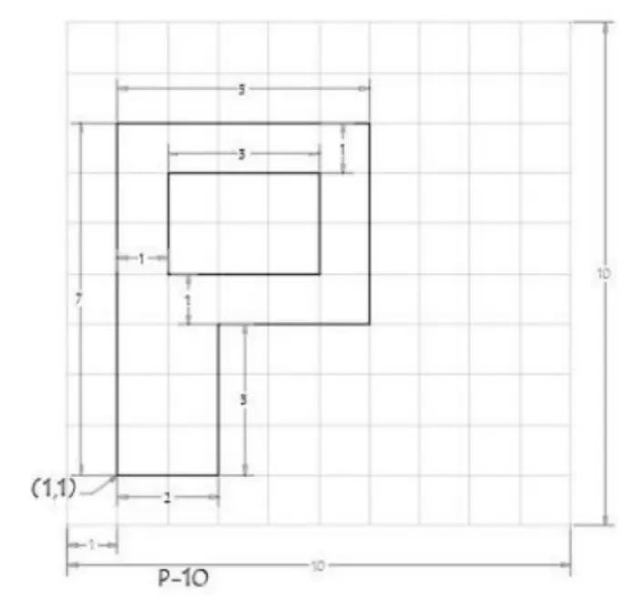
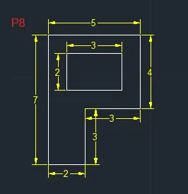
- First point to be given is 1,1. It asks to specify the next point simultaneously after each next point entered
- Type @7<90
- Next type @5<0
- Next type @4<270
- Next type @3<180
- Next type @3<270
- Next type @2<180 or CLOSE
- In Command box type LINE, asks to specify the first point
- First point to be given is 2,5. It asks to specify the next point simultaneously after each next point entered
- Type @2<90
- Next type @3<0
- Next type @2<270
- Next type @3<180 or CLOSE to get the give Geometry.
Result:
P9 Profile Wood
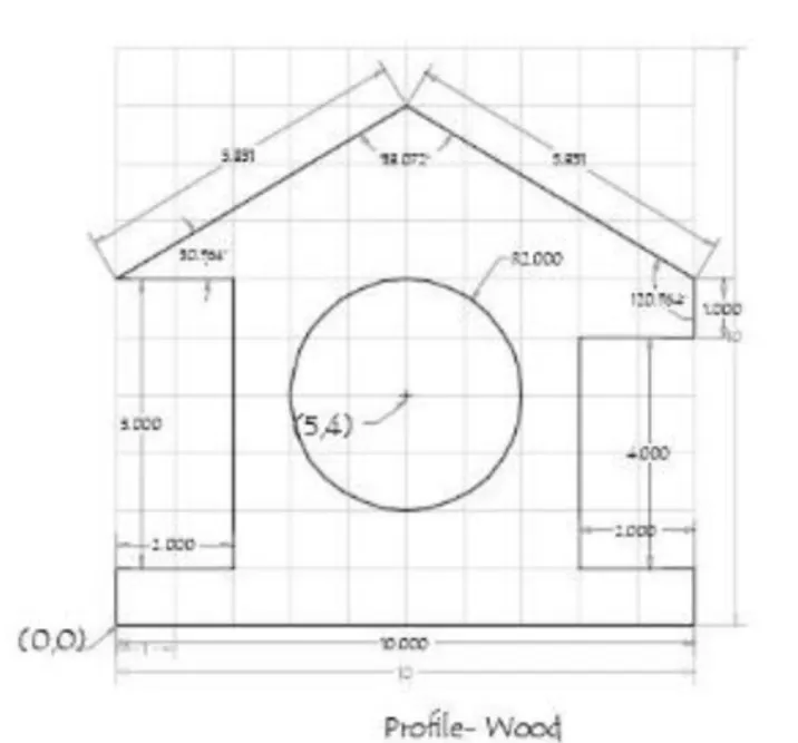
Absolute Coordinate system
Procedure:
- Click on AutoCad application to run the application.
- Type QNEW in command bar and enter
- Select default setting as Imperial (feet or inches)
- In the default setting, click on use a wizard, and in that advance setting, set the unit as decimal and precision as 0 and press next
- Set angle as decimal degree and precision as 0 then click next
- Set angle measure as east and next step
- Angle direction to be set in Counter-Clockwise direction
- Area to be given as length 10 and width 10
- Finish, then the new workspace appears
- In Command box type LINE, asks to specify the first point
- First point to be given is 0,0. It asks to specify next point simultaneously after each next point entered
- Specify point 10,0
- Specify point 10,1
- Specify point 8,1
- Specify point 8,5
- Specify point 10,5
- Specify point 10,6
- Specify point 5,9
- Specify point 0,6
- Specify point 2,6
- Specify point 2,1
- Specify point 0,1
- Type CLOSE
- In home tab click on Circle (centre and radius)
- Then command bar asks to specify centre point of circle
- Type 5,4
- Command bar asks to specify radius of circle
- Type 2 and the desired Geometry is done.
Result:

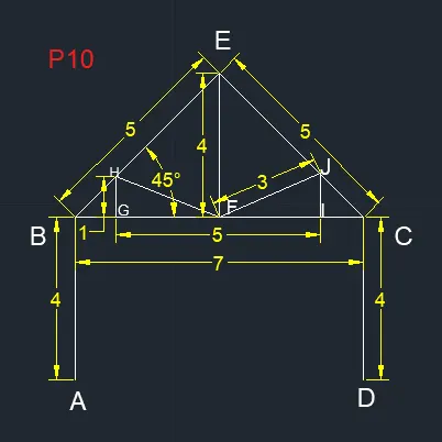
P10 Queen Post Truss:
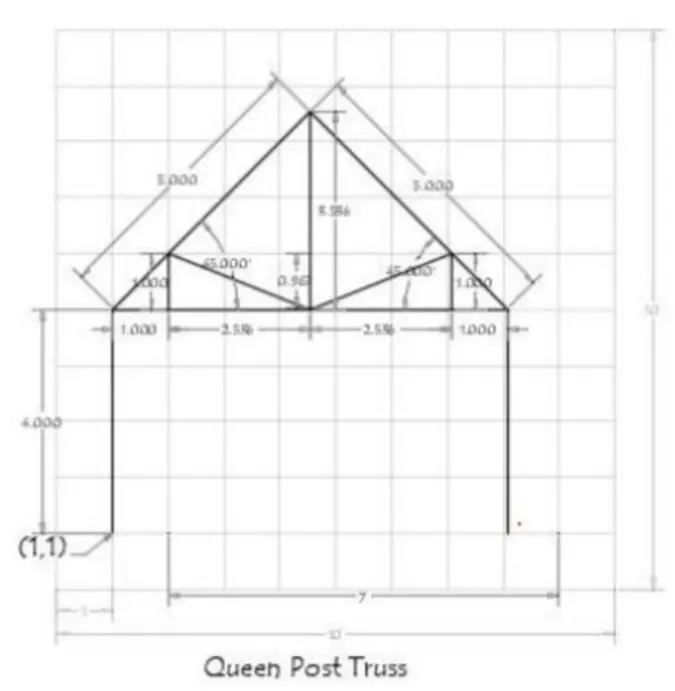
Relative Polar Coordinate System
Procedure:
- Click on AutoCad application to run the application.
- Type QNEW in command bar and enter
- Select default setting as Imperial (feet or inches)
- In the default setting, click on use a wizard, and in that advance setting, set the unit as decimal and precision as 0 and press next
- Set angle as decimal degree and precision as 0 then click next
- Set angle measure as east and next step
- Angle direction to be set in Counter-Clockwise direction
- Area to be given as length 10 and width 10
- Finish, then the new workspace appears
- In Command box type LINE, asks to specify the first point
- First point to be given is 1,1. It asks to specify the next point simultaneously after each next point entered
- Type @4<90
- Next type @7<0
- Next type @4<270
- Press enter
- Again take line command
- Specify first point as 1,5
- type @5<45
- Press Enter
- Again take line command
- Specify point 8,5
- type @5<135
- Next type @3.5<270
- Press Enter
- Again take line command
- Specify first point as 1,5
- Then type @1<0
- Next type @1<90
- Join line HF
- Press Enter
- Again take line command
- Specify first point as 8,5
- Then type @1<180
- Next type @1<90
- Join line JF and the required Geometry is done.
Result:
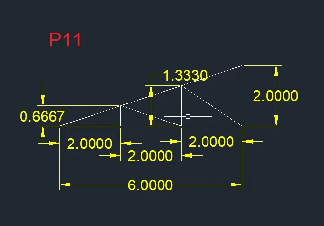
P11 Mono Pitch
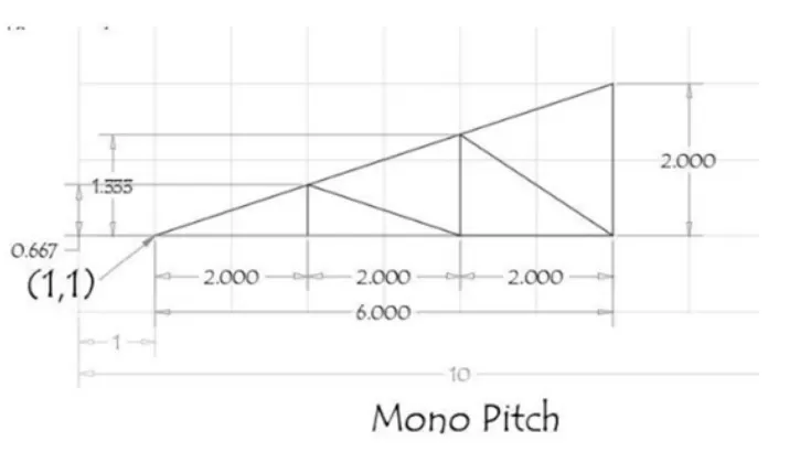
Absolute Coordinate system
Procedure:
- Click on AutoCad application to run the application.
- Type QNEW in command bar and enter
- Select default setting as Imperial (feet or inches)
- In the default setting, click on use a wizard, and in that advance setting, set the unit as decimal and precision as 0 and press next
- Set angle as decimal degree and precision as 0 then click next
- Set angle measure as east and next step
- Angle direction to be set in Counter-Clockwise direction
- Area to be given as length 10 and width 10
- Finish, then the new workspace appears
- In Command box type LINE, asks to specify the first point
- First point to be given is 1,1. It asks to specify next point simultaneously after each next point entered
- Specify point 3,1
- Specify point 5,1
- Specify point 7,1
- Specify point 7,3
- Type CLOSE
- Select LINE option from home tab.
- Command bar asks to specify first point
- Specify point 3,1
- Specify point 3, 1.667
- Specify point 5,1
- Specify point 5, 2.333
- Specify point 7,1
- The required Geometry is done.
Result:
THANK YOU.