Creating a Floor plan, Footing detail and Isometric view using AutoCad
Creating a Floor plan, Footing detail and Isometric view using AutoCad
C1
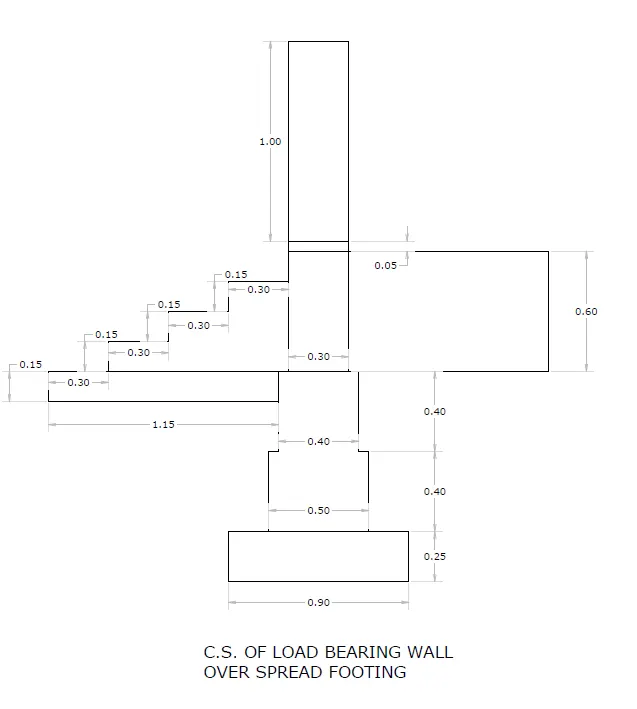
AIM: To draw the cross-section of Load bearing wall over spread footing.
PROCEDURE:
- Click on the AutoCad application to open the application
- Type QNEW in the command bar and press enter
- Default setting to Imperial (feet and inches)
- Unit to be set as decimal and precision as 0.00 and press next
- Angle to be set as decimal degree and precision as 0
- Angle direction as Counter Clockwise and press next
- Angle measure is EAST, Angle direction is Counter Clockwise
- The area provided is 5 by 5 and press Finish
- Keep snap and grid setting off
- From the Home tab click on the rectangle in the draw panel
- In command bar it asks to specify first corner point (2,1)
- In front of specify second corner select dimension and take length as 0.9 and width as 0.25 and enter
- Again take rectangle command and specify first point as 2.2, 1.25
- Specify second point corner select dimension and take length as 0.9 and width as 0.25 and enter
- Take rectangle command and specify first corner point as 2.25, 1.65
- Specify second point corner select dimension and take length as 0.40 and width as 0.40 and enter
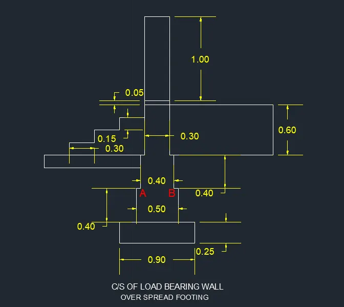
- Trim line AB
- Take rectangle command and specify first corner point as 2.30, 2.65
- Specify second point corner select dimension and take length as 0.30 and width as 0.60 and enter
- Take rectangle command and specify first corner point as 2.30 and 2.65
- Specify second point corner select dimension and take length as 0.30 and width as 0.05 and enter
- Take rectangle command and specify first corner point as 2.30, 2.70
- Specify second point corner select dimension and take length as 0.30 and width as 1.00 and enter
- Take rectangle command and specify first corner point as 2.25, 1.90
- Specify second point corner select dimension and take length as 1.15 and width as 0.15 and enter
- Take line command and specify first point as 1.10, 1.90
- Specify next point as @0.30<0
- Specify next point as @0.15<90
- Specify next point as @0.30<0
- Specify next point as @0.15<0
- Specify next point as @0.30<0
- Specify next point as @0.15<90
- Specify next point as @0.30<0
- Press enter
- Give dimensions to the respected rectangle and lines by using dimension command from the annotation tab
- The C.S of load bearing wall over spread footing is done.
RESULT:
C2
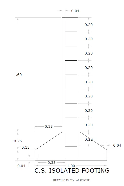
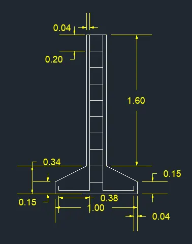
AIM: To draw c.s of isolated footing.
PROCEDURE:
- Click on the AutoCad application to open the application
- Type QNEW in the command bar and press enter
- Default setting to Imperial (feet and inches)
- Unit to be set as decimal and precision as 0.00 and press next
- Angle to be set as decimal degree and precision as 0
- Angle direction as Counter Clockwise and press next
- Angle measure is EAST, Angle direction is Counter Clockwise
- The area provided is 5 by 5 and press Finish
- Keep snap and grid setting off
- From the Home tab click on the rectangle in the draw panel
- In the command bar, it asks to specify first corner point (1,1)
- In front of specify the first point, specify 1,1
- In the specify second point select dimension and take the length as 1 and width as 0.40 and enter.
- Take a chamfer option from the modified tab
- Command bar will ask to select line or to trim, distance, und0, angle etc.
- In chamfer select trim setting as trim and click on distance
- Specify first chamfer distance as 0.25
- Specify second chamfer distance as 0.38 and enter
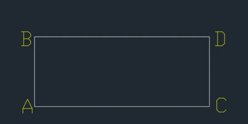
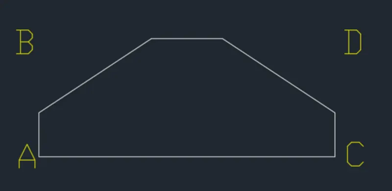
- Select line AB and then select BD
- Select chamfer option from the modified tab
- Command bar will ask to select line or to trim, distance, undo, angle etc.
- In chamfer select trim setting as trim and click on distance
- Specify first chamfer distance as 0.25
- Specify second chamfer distance as 0.38 and enter
- Now firstly select line CD and then select line CB
- It forms as shown below
- Trim above BD line using Trim command
- Measure coordinates of the point B by using coordinates command from the command bar
- We get coordinates of B as 1.38,1.40
- Take line command and specify first point as 1.38,1.40
- Specify next point as @1.60<90
- Specify next point as @0.24<0
- Specify next point as @1.60<270 and press Enter
- Measure the coordinates of the point P by using coordinates command from the command bar
- We ger coordinates of P as 1.38,3
- Take a line command and specify first point as 1.38,3
- Specify next point as @0.04<0, we get point Q
- Measure the coordinates of the point Q using coordinates command we get coordinates of Q as 1.42,3
- Take rectangle command and specify first corner points 1.42,3
- Select dimensions as length 01.16 and width as 0.20 and enter
- Take copy command from command bar and select rectangle as a object from cursor and enter
- Take base point of rectangle as bottom left corner with the help of cursor
- Click on array, edit number of items on the array as 9 and press enter, click on Fit
- Specify second point as @1.6<270
- Select line command and specify first point as 1.04,1.04 (point S)
- Specify second point as @0.92,0 (point R)
- Measure the coordinates of point R, it is 1.96,1.04
- Use the fillet command by setting fillet radius 0 and join.
- Select line command and specify point as 1.04,1.04 (Point S)
- Specify second point as @0.38,0
- Use the fillet command by setting fillet radius ) and join
- Give the dimensions as per the drawing and CS of isolated footing is done.
RESULT:
C3
Line Diagram of a Two Bedroom Building
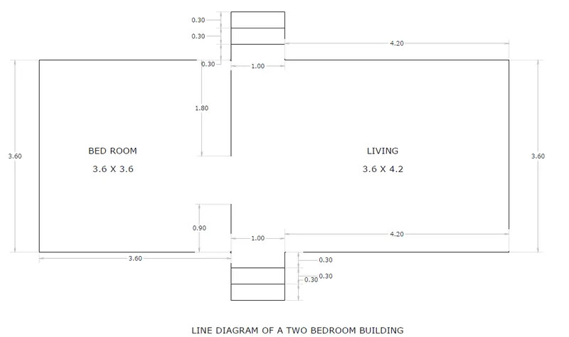
AIM: To draw line diagram of a two bedroom building
PROCEDURE:
- Click on AutoCad application to open the application
- Type QNEW in command bar and press enter
- Default setting to metric
- Unit to be set as decimal and precision as 0.00 and press next
- Angle to be set as decimal degree and precision as 0
- Angle direction as Counter Clockwise and press next
- Angle measure is EAST, Angle direction is Counter Clockwise
- Area provided is 5 by 5 and press Finish
- Keep snap and grid setting off
- Select line command and specify first point as 1,1
- Specify next point as @3.60<0
- Specify next point as @0.90<270
- Specify next point as @1.00<0
- Specify next point as @0.90<90
- Specify next point as @4.20<180
- Specify next point as @3.60<90
- Specify next point as @4.20<180
- Specify next point as @0.90<90
- Specify next point as @1.00<180
- Specify next point as @0.90<270
- Specify next point as @3.60<180
- Specify next point as @3.60<270
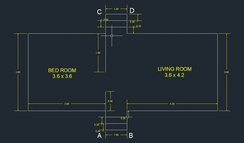
- By using offset command from the command bar, give 2 offset to the line AB and line CD at a distance of 0.3 and 0.6
- The points A,B,C,D are given just for reference
- From Home tab click on line
- Then command bar ask us to specify first point
- In front specify first point press 4.60,1.00
- In front specify next @0.90<90
- Take line command bar and specify first point as 4.60,4.60
- Specify next point @1.80<270
- Give dimensions and line diagram of two bedroom building is done.
RESULT:
C4
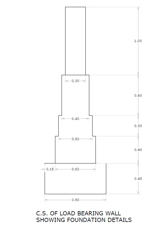
CS of load bearing wall showing foundation details:
AIM: To draw CS of load bearing wall showing foundation details
PROCEDURE:
- Click on the AutoCad application to open the application
- Type QNEW in the command bar and press enter
- Default setting to Imperial (feet and inches)
- Unit to be set as decimal and precision as 0.00 and press next
- Angle to be set as decimal degree and precision as 0
- Angle direction as Counter Clockwise and press next
- Angle measure is EAST, Angle direction is Counter Clockwise
- The area provided is 5 by 5 and press Finish
- Keep snap and grid setting off
- Take rectangle command and specify first corner point as 1,,1
- specify second corner point select dimension and take length as 0.90 and width as 0.45
- Again take rectangle command and specify first corner point as 1.15,1.45
- specify second corner and dimensions are length 0.60 and width 0.40
- Take rectangle command and specify first corner point as 1.20,1.85
- Specify second corner select dimension and length as 0.50 and width as 0.30
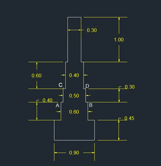
- Turn the line AB and line CD by using trim command from the command bar
- Take rectangle command and specify first corner point as 1.25,2.15
- Specify second corner select dimension length as 0.40 and width as 0.60
- Again take rectangle command and specify first corner point as 1.30,2.75
- Specify second corner select dimension and length is 0.30 and width is 1.00
- Mark the dimensions and CS of load bearing wall is completed.
RESULT:
C5
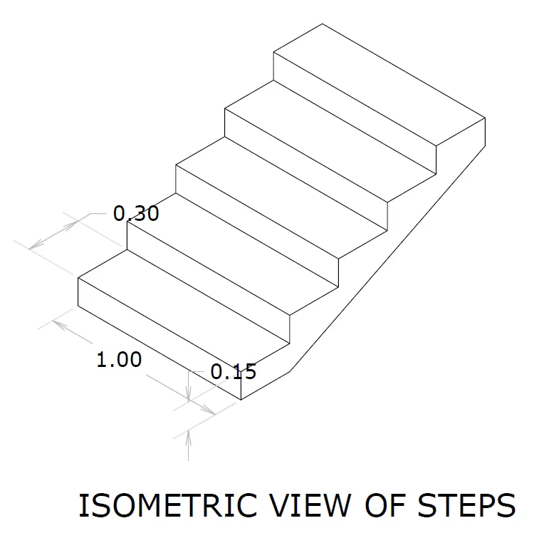
AIM: To draw isometric view of steps
PROCEDURE:
- Click on the AutoCad application to open the application
- Type QNEW in the command bar and press enter
- Default setting to Imperial (feet and inches)
- Unit to be set as decimal and precision as 0.00 and press next
- Angle to be set as decimal degree and precision as 0
- Angle direction as Counter Clockwise and press next
- Angle measure is EAST, Angle direction is Counter Clockwise
- The area provided is 5 by 5 and press Finish
- Keep snap and grid setting off
- Select snap type as isometric snap and take ortho from status bar
- Take line command and specify a point
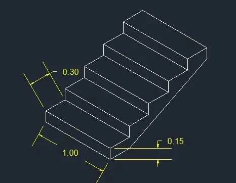
- Type distance as 1 and prsee F5 to get the next line in desired direction
- In the command prompt type 0.15 as distance
- Press F5 to get the desired direction and specify distance as 0.30
- Press F5 to get line in desired direction
- Continue these steps until all the steps are formed.
RESULT:
C6
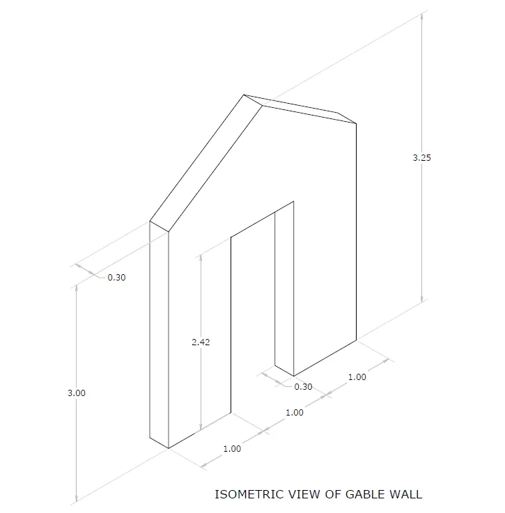
AIM: To draw isometric view of Gable Wall.
PROCEDURE:
- Click on the AutoCad application to open the application
- Type QNEW in the command bar and press enter
- Default setting to Imperial (feet and inches)
- Unit to be set as decimal and precision as 0.00 and press next
- Angle to be set as decimal degree and precision as 0
- Angle direction as Counter Clockwise and press next
- Angle measure is EAST, Angle direction is Counter Clockwise
- The area provided is 5 by 5 and press Finish
- Keep snap and grid setting off
- Select isomeetric snap and keep ortho on
- Take line command and select a first point
- Using F5 to get desired direction, plot all the lines along with their measurements as shown is the above figure.
RESULT:

THANK YOU.