Creation of geometries by Coordinate system methods using AutoCad
1)
Aim:
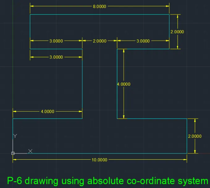
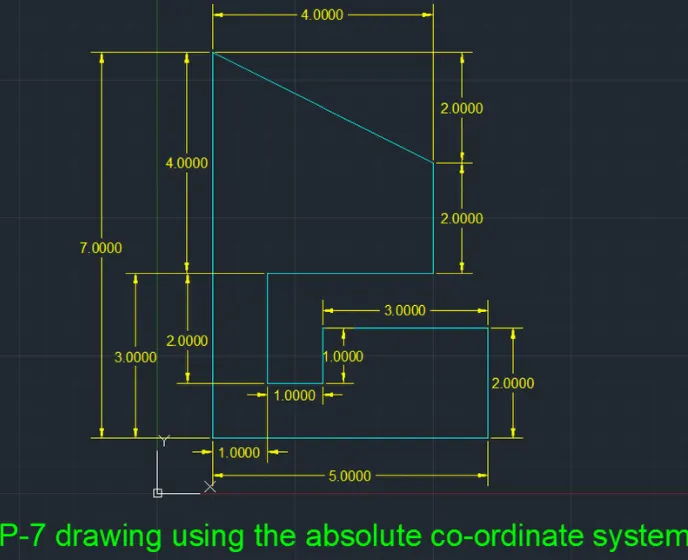
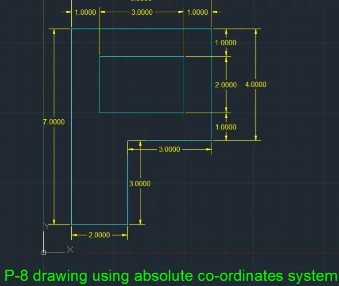
To draw the given geometries using absolute coordinate system.
Definition:
Absolute coordinate entry is the default. Absolute coordinate entry always counts from the origin. When drawing lines, AutoCAD is ready to place the next vertex wherever you tell it to go.
Commands used:
- Unit
- Line
- Dimlinear
- Text
- Cricle
Template used:
Imperial
Unit system:
Decimal
Procedure (with rough example):
Consider a line to be drawn of coordinated (4,6) and (5,3)
- Type L on the command line and press enter
- Type 4,6 on the command line and press enter
- Type 5,3 on the command line and press enter
- Press enter to finish the Line command
It made a segment between those two points. The first point is 4 to the right and 6 up from the origin. The second point is 5 to the right and 3 up from the origin. The line is the shortest distance between those two points.
Geometries:
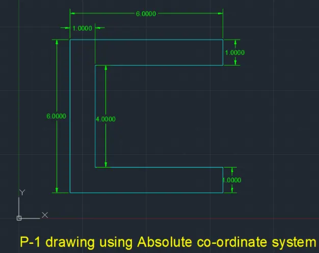
-P1
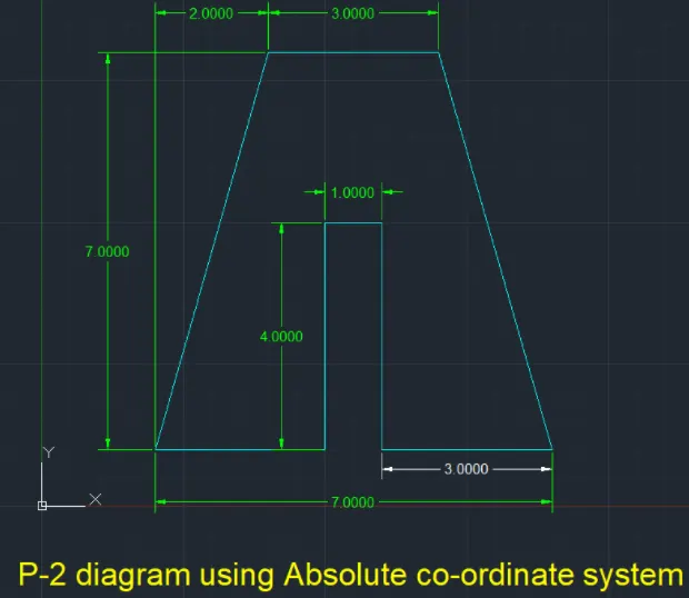
-P2
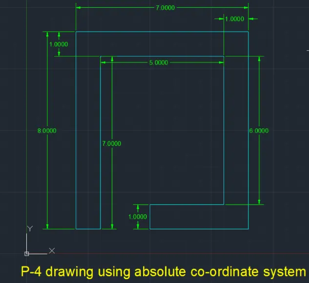
-P3
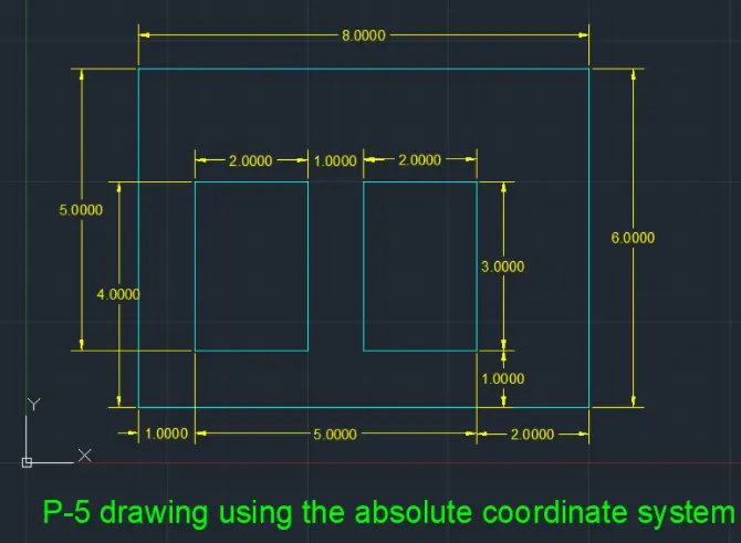
-P5
-P6
-P7
-P8
_________________________________________________________________________________________
2)
Aim:
To draw the given geometries using absolute relative coordinate system.
Definition:
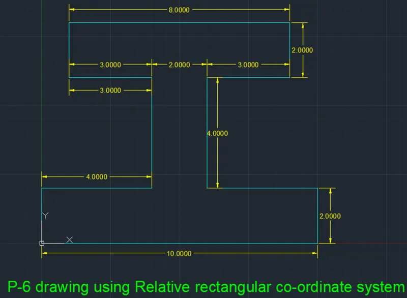
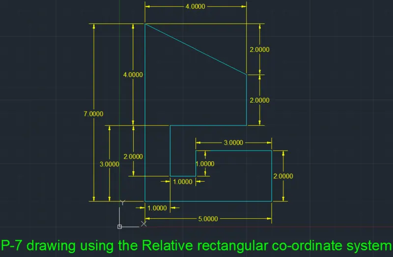
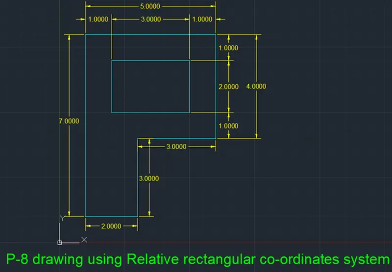
For relative coordinates, AutoCAD does not count from 0,0. Instead, the reference point is the previous point in the drawing. AutoCAD recognizes the @ symbol as instructions to count using relative coordinates.
Commands used:
- Unit
- Line
- Dimlinear
- Text
- Cricle
Template used:
Imperial
Unit system:
Decimal
Procedure (with rough example):
Consider a line to be drawn of coordinated (4,6) and (5,3)
- Type L on the command line and press enter
- Type 4,6 on the command line and press enter
- Type @5,3 on the command line and press enter
- Press enter to finish the line command
AutoCAD counted 5 over and 3 up from the first vertex, and made the line between those two locales.
Geometries:
-P1
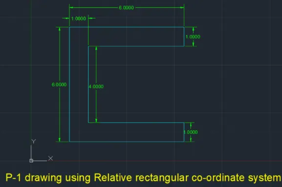
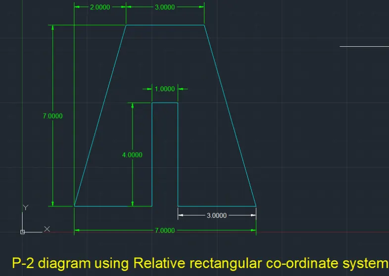
-P2
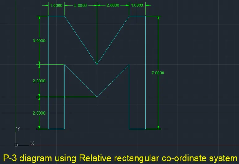
-P3
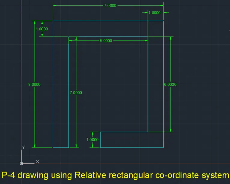
-P4
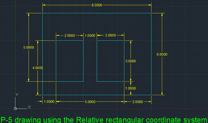
-P5
-P6
-P7
-P8
________________________________________________________________________________________________________
3)
Aim:
To draw the given geometries using relative polar coordinate system.
Definition:
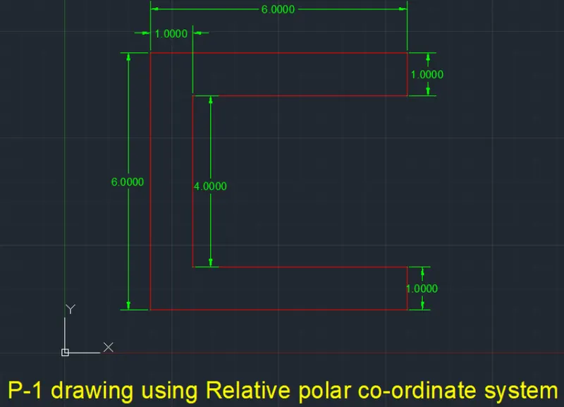
Polar coordinates are named for their “pole”; the reference point to start counting from, which is similar in concept to the origin. Polar coordinates employ one radial distance and one angle (by convention, the angle is measured counterclockwise from the x-axis). The angle signifies the direction, and the distance is how far to go in that direction from the pole.
Polar coordinates in AutoCAD are given as R<Degrees, where:
- “R” is the radial distance
- “<” is the less than sign (but in this case represents the angle)
- “Degrees” is the value of the angle in degrees
The analogue to ORTHO mode is POLAR tracking (F10). Polar tracking restricts cursor movement to specified angles. The user can specify the acceptable angle increments by right-clicking the icon
Commands used:
- Unit
- Line
- Dimlinear
- Text
- Cricle
Template used:
Imperial
Unit system:
Decimal
Procedure (with rough example):
Consider a line to be drawn of coordinated (4,6) and (5,3)
- Type L on the command line and press enter
- Type 4,6 on the command line and press enter
- Type @5<60 on the command line and press enter
- Press enter to finish the line command
We input the polar coordinates as @5<60, which means the length of the line is 5 and the angle counterclockwise from the x-axis is 60 degrees.
Geometries:
-P1
-P2
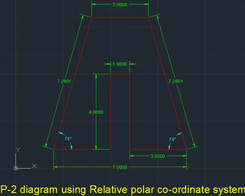
-P3
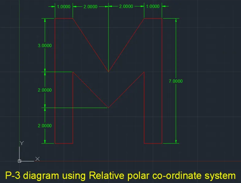
-P4
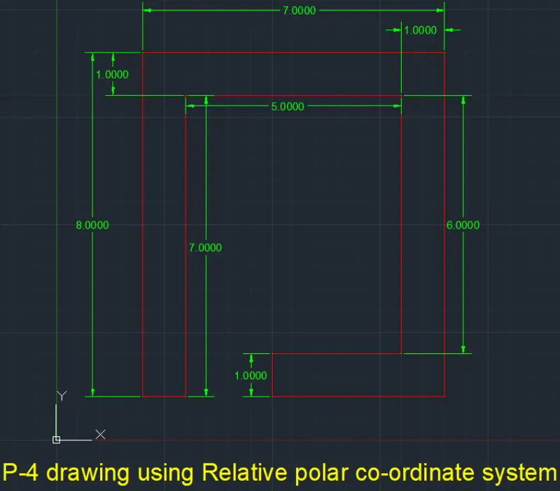
-P5
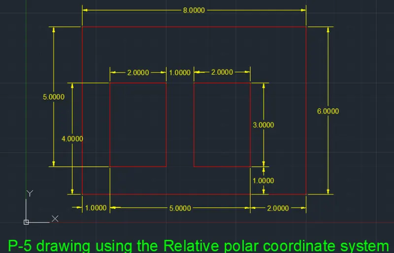
-P6
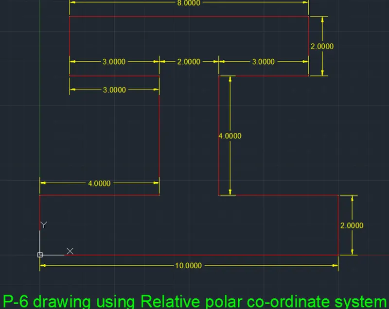
-P7
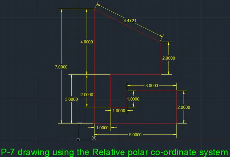
-P8
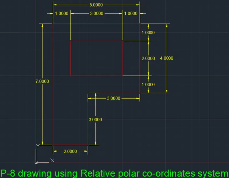
________________________________________________________________________________________________________
4)
Aim:
To draw the profile and the trusses using any coordinate system methods.
Definition:
Absolute coordinate entry is the default. Absolute coordinate entry always counts from the origin. When drawing lines, AutoCAD is ready to place the next vertex wherever you tell it to go.
Commands used:
- Unit
- Line
- Dimlinear
- Text
- Cricle
Template used:
Imperial
Unit system:
Decimal
Method used:
Absolute Coordinate system
Profiles:
-Profile Wood
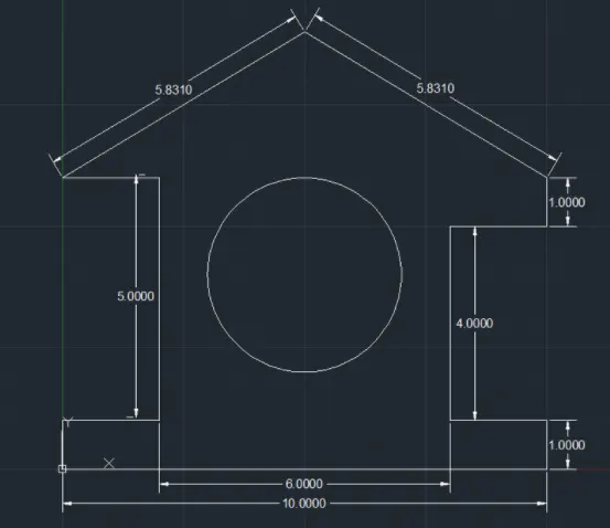
-QueenPost
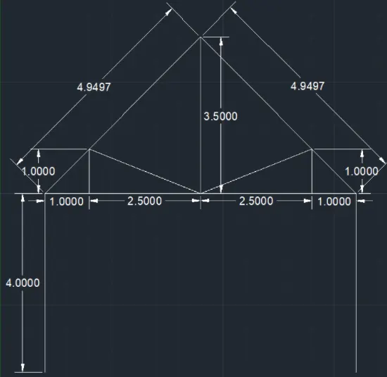
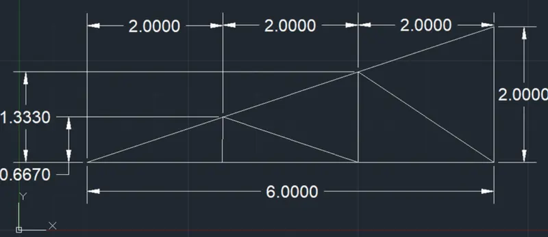
-MonoPitch
________________________________________________________________________________________________________