Creating a Floor plan, Footing detail and Isometric view using AutoCad
C1
AIM:
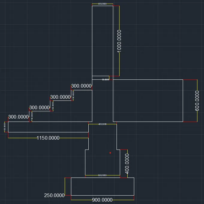
To draw the CS of load bearing wall over spread footing
Template:
Imperial
Unit:
Decimal (all dimensions are in mm)
Given Sketch:
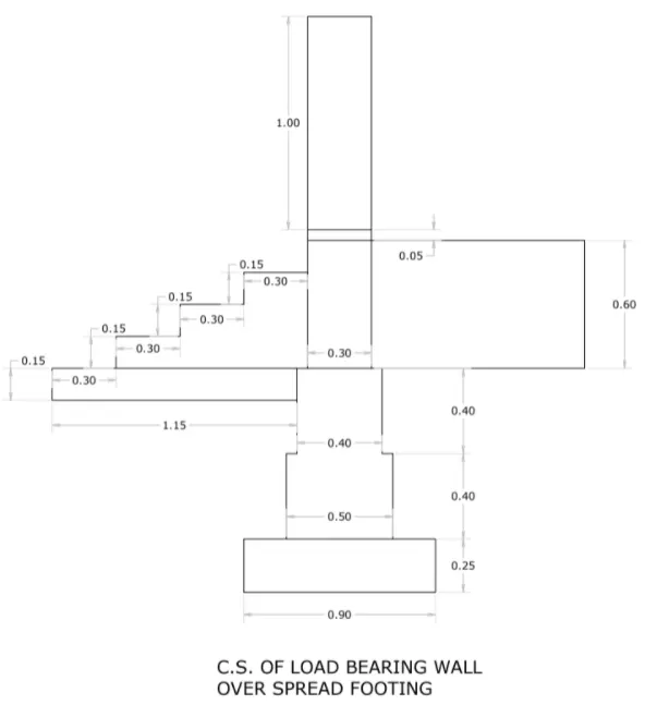
Method:
Direct dimension.
Before Starting up:
- Ortho mode ON
- Enabling Centre line, intersection in the ortho snap settings
Procedure:
- Type Rectangle or Rec in the command box.
- Enter D and provide dimension of 900 (length) and 250 (height).
- Bisect the rectangle using Line command with a rough length.
- Draw another rectangle of dimension of length 500 (length) and 400 (height), so that the mid point of this rectangle intersects the previous one.
- Draw another rectangle of dimension of length 400 (length) and 400 (height), so that the mid point of this rectangle intersects the previous one.
- Using the trim command, trim the inner edges.
- Using the offset, create an offset of dimension 50 over the top edge and join the openings using the extend command.
- Draw another rectangle of dimension of length 300 (length) and 1000 (height), so that the mid point of this rectangle intersects the previous one.
- By the above steps we should have achieved a sketch like the below;
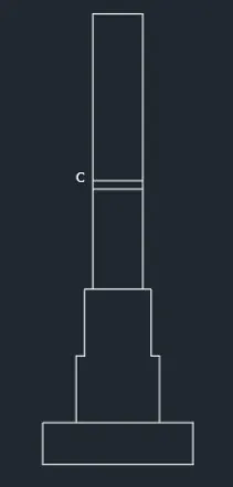
- From the C point, using the line command, draw line of dimension 150 towards the left, 300 downwards from the previous point, 150 towards the left from the previous point , 300 downwards from the previous point, 150 towards the left from the previous point , 300 downwards from the previous point, 150 towards the left from the previous point , and 300 downwards from the previous point and close the figure towards the edge.
- By the end we could get a sketch like this;
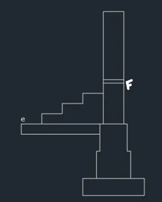
- From F, using REC command, draw a rectangle of dimension 1000 lenght and 600 height
- By the end we could achieve a sketch as below;
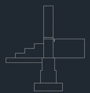
- Usind Dimension command give the dimensions.
Final Product:
________________________________________________________________________________________________________
C2
AIM:
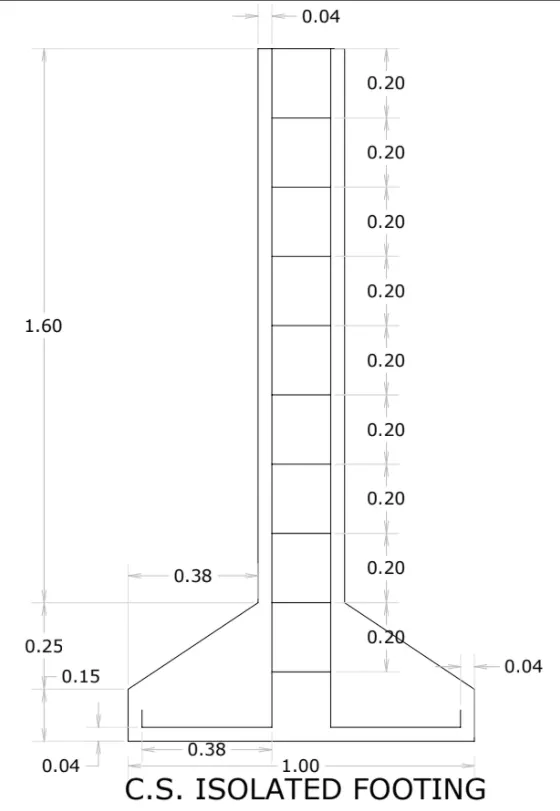
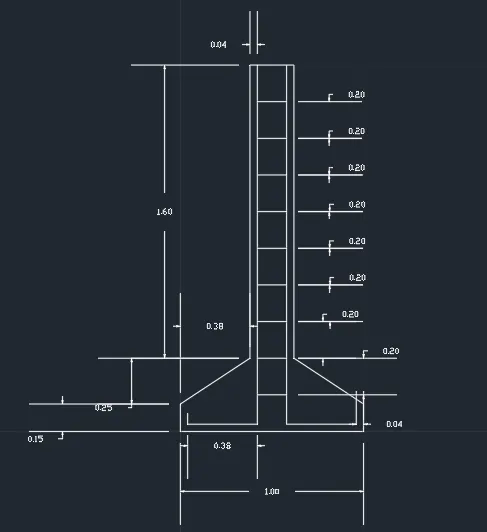
To draw the CS of isolated footing
Template:
Imperial
Unit:
Decimal (all dimensions are in inches)
Given Sketch:
Method:
Direct dimension.
Before Starting up:
- Ortho mode ON
- Enabling Centre line, intersection in the ortho snap settings
Procedure:
- Type Rectangle or Rec in the command box.
- Enter D and provide dimension of 0.50 (length) and 0.40 (height).
- Using Chamfer command, with distance selected, ( first distance as 0.25 and second one as 0.38, ) select the left two edge line to get an chamfer.
- Using Line command, draw two lines of length 1.60 perpendicular to the top corners of the rectangle.
- Offset all the left edges and the bottom edge of the given figure with an offset length of 0.40.
- Using line tool, connect the left and the right corner over the top.
- With ARRAY command, select the previous line and in path mode, select the right edge , and make the array of offset 0.20 and of 10 numbers.
- Select all, and using Mirror Command, mirror the whole sketch using right edge as the referene, and say no to erase the previous one.
- Delete the middle line.
- Using trim command, trim the unwanted intersected lines.
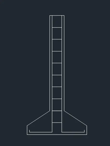
- Atlast we should have achieved a final sketch as below;
- Mark all the dimension using the dimension command.
Final Product:
________________________________________________________________________________________________________
C3
AIM:
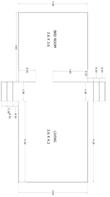
To draw line diagram of two bedroom Building
Template:
Imperial
Unit:
Decimal (all dimensions are in inches)
Given Sketch:
Method:
Direct dimension.
Before Starting up:
- Ortho mode ON
- Enabling Centre line, intersection in the ortho snap settings
Procedure:
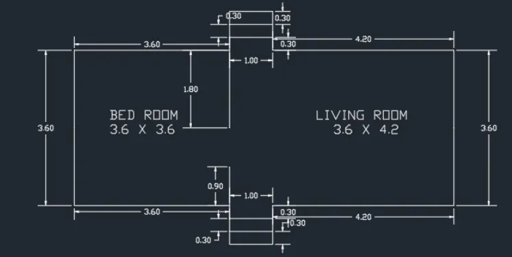
- Draw a rectangle of dimension 3.6 (lenght) and 3.6 (height) using REC command.
- Draw another rectangle of dimension 4.2 (lenght) and 3.6 (height) using REC command, so that it is attached to the right edge of the prevoius rectangle
- Draw three rectangles of dimension 1.0 (lenght) and 0.30 (height) attached over the other, from the points which connects the both rectangles, both up and down. This should be towards the bigger rectangle.
- Mark the dimension using Dimension command.
- Using MTEXT command name the two rooms along with their dimensions respectively.
Final product:
____________________________________________________________________________________________________
C4
AIM:
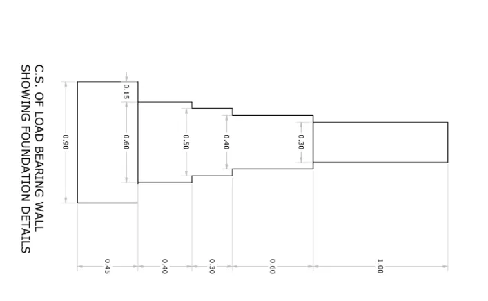
To draw line diagram of two bedroom Building
Template:
Imperial
Unit:
Decimal (all dimensions are in mm)
Given Sketch:
Method:
Direct dimension.
Before Starting up:
- Ortho mode ON
- Enabling Centre line, intersection in the ortho snap settings
Method:
Direct dimension.
Before Starting up:
- Ortho mode ON
- Enabling Centre line, intersection and isometric snap (ON) in the ortho snap settings
Procedure:
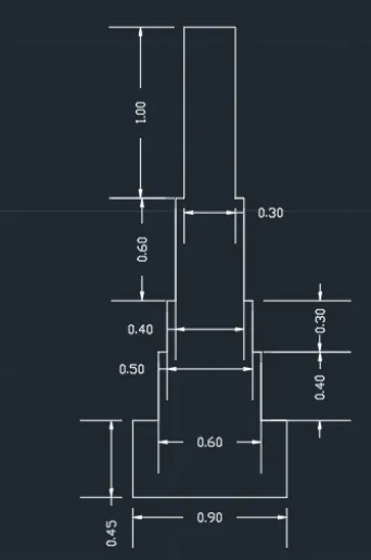
- Draw a rectangle of dimension 0.90 (length) and 0.45 (height), using REC command.
- Using REC command, draw a rectangle of dimension 0.60 (length) and 0.40 (height), and make sure that the mid point of top edge of previously drawn rectangle interesct the mid point of bottom edge of this rectangle.
- Using REC command, draw a rectangle of dimension 0.50 (length) and 0.30 (height), and make sure that the mid point of top edge of previously drawn rectangle interesct the mid point of bottom edge of this rectangle.
- Using REC command, draw a rectangle of dimension 0.40 (length) and 0.60 (height), and make sure that the mid point of top edge of previously drawn rectangle interesct the mid point of bottom edge of this rectangle.
- Using REC command, draw a rectangle of dimension 0.30 (length) and 1.00 (height), and make sure that the mid point of top edge of previously drawn rectangle interesct the mid point of bottom edge of this rectangle
- Mark all the dimensions using D command.
Final Product:
____________________________________________________________________________________________________
C5
AIM:
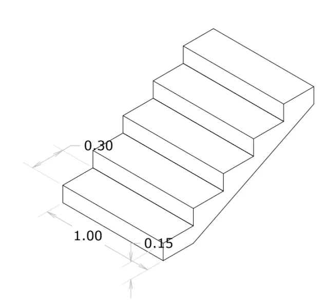
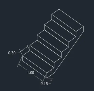
To draw Isometric view of steps
Template:
Imperial
Unit:
Decimal (all dimensions are in m)
Given Sketch:
Before Starting up:
- Ortho mode ON
- Enabling Centre line, intersection in the ortho snap settings
Method:
Direct dimension.
Before Starting up:
- Ortho mode ON
- Enabling Centre line, intersection and isometric snap (ON) in the ortho snap settings
Procedure:
- Type PL command and press enter, specify a start point (say a ).
- Take isoplane left, specify the next point at 1 (towards NW).
- Take isoplane right, specify next point .15 ( towards N).
- Specify next point at 1 ( towards SE ).
- Specify next point at .15 ( towards E ).
- Again, with the same PL command selected, select a corner from the front one.
- Take isoplane top.
- Specify next point at .30 ( towards NE )
- Specify next point at 1 ( towards NW)
- Specify next point at .30 (towards SW)
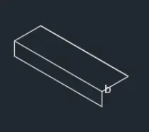
- Using CO command, select the complete step and press enter.
- Select b as the base point and place it 4 time over each other.
- draw a line of dimension .15 from the bottom right corner towards S, from there another line of dimension 0.30 towards NE, another one of dim .15 from the top right corner. Now connect the opening using a line.
Final Product:
____________________________________________________________________________________________________
C6
AIM:
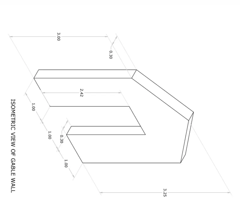
To draw isometric of gable wall
Template:
Imperial
Unit:
Decimal (all dimensions are in mm)
Given Sketch:
Before Starting up:
- Ortho mode ON
- Enabling Centre line, intersection in the ortho snap settings
Method:
Direct dimension.
Before Starting up:
- Ortho mode ON
- Enabling Centre line, intersection and isometric snap (ON) in the ortho snap settings
Procedure:
- Draw a rectangle of dimension 3.0 (length) and 3.25 (height) using REC command.
- Using Chamfer command, and select distance. specify the first distance as 0.25 and second as 1.5. Chamfer on both the sides like below.
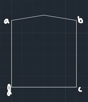
- Join the poins a and b using Line command.
- Select all, and type X in the command line and press enter.
- Off set the line a and d towards right, two times, with offset length 1.
- Offset the line dc upward with offset length 2.42.
- By the end we may get a sketch like this.
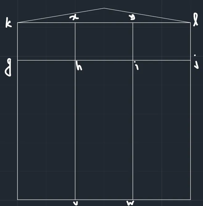
- Using trim command, erase lines kl, xh, yi, and vw.
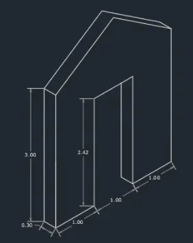
- Pan towatda a NE or NW so that it is a 3d view.
- Using Extrude command, select all the object and extrude to a distance of 0.30.
- Mark the dimensions usind D command.
Final Product:
________________________________________________________________________________________________________