Creation of geometries by Coordinate system methods using AutoCad
1)AIM:- To create geometry in Autocad using all the coordinates system methods.
Introduction of coordinates system:-
There are four coordinates system:-
.Absolute system
.Relative coordinates system
.Relative polar system
.Direct distance entry
.Absolute system:-
.In the absolute coordinates system, all inputs points specified in the drawing are with respect to origin(0,0)
.Relative coordinates system:-
.In the relative coordinates system, the first point is entered with respect to origin(0,0) & all next points can be entered by specifying the next coordinates with respect to the first point.
.The relative coordinates started with the symbol '@' .In relative rectangular coordinates, system points are entered by typing '@X, Y' & pressing enter.
.Polar coordinates:-
.Polar coordinates used when we need to draw the next points at a specified angle.
.Polar coordinates system system in Autocad specifies distance length at an angle.
.In relative polar coordinates system points are entered by typing '@distance<angle '& pressing enter.
.Direct distance entry:-
.It is the sampling method of drawing.
.Direct distance entry enables to draw an object by pointing in a pointing particular direction with the cursor & entering a distance at a command box.
.First point ids entered with entered respect to origin(0,0) & then the cursor is move in the particular direction & distance is entered at command box.
AIM:- To create geometry in Autocad using all the coordinates system methods.
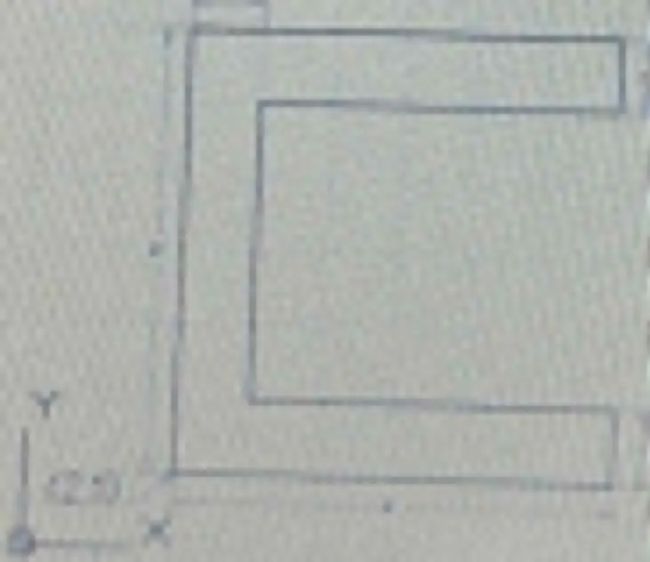
Procedure:-
Step1:-On the AutoCAD software set up the units to imperial template& decimal system 0.000
.STEP2:-Set the limits in the command by using 'LIM' before drafting.
.STEPS OF CREATING IN AUTO CAD SOFTWARE BY ABSOLUTE COORDINATES SYSTEM:-
.Type the command 'L' for the line & specify the coordinates for starting point 1(2,1)
.Type the next coordinates of the point 2(8,1) in the command box.
.Type the next coordinates of the point 3(8,2) in the command box.
.Type the next coordinates of the point 4(3,2) in the command box.
.Type the next coordinates of the point 5(3,6) in the command box.
.Type the next coordinates of the point 6(8,6) in the command box.
.Type the next coordinates of the point 7(8,7) in the command box.
.Type the next coordinates of the point 8(2,7) in the command box.
.Click close in the command box.
RESULT:-
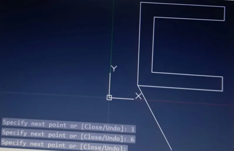
.STEPS OF CREATING IN AUTO CAD SOFTWARE BY RELATIVE RECTANGULAR COORDINATES SYSTEM:-
.Type the command 'L' for the line & specify the coordinates for starting point 1(2,1).
.Type the next coordinates of point 2@6,0 in the command box.
.Type the next coordinates of point 3@0,1 in the command box.
.Type the next coordinates of point 4@-5,0 in the command box.
.Type the next coordinates of point 5@0,4 in the command box.
.Type the next coordinates of point 6@5,0 in the command box.
.Type the next coordinates of point 7@0,1 in the command box.
.Type the next coordinates of point 8@-6,0 in the command box.
.Click close on the command box.
RESULT:-
.STEPS OF CREATING IN AUTO CAD SOFTWARE BY RELATIVE POLAR COORDINATES SYSTEM:-
.Type the command 'L' for the line & specify the coordinates for starting point 1(2,1).
.Type the next coordinates of point 2@6<0 in the command box.
.Type the next coordinates of point 3@1<90 in the command box.
.Type the next coordinates of point 4@5<180 in the command box.
.Type the next coordinates of point 5@4<90 in the command box.
.Type the next coordinates of point 6@5<0 in the command box.
.Type the next coordinates of point 7@0<90 in the command box.
.Type the next coordinates of point 8@6<180 in the command box.
.Click close on the command box.
RESULT:-
.STEPS OF CREATING IN AUTO CAD SOFTWARE BY DIRECT DISTANCE ENTRY SYSTEM:-
.Type the command 'L' for the line & specify the coordinates for starting point 1(2,1).
.Type the length 6 in the command box to +ve X axis for point 2.
.Type the length 1 in the command box to +ve Y axis for point 3.
.Type the length 5 in the command box to -ve X axis for point 4.
.Type the length 4 in the command box to +ve Y axis for point 5.
.Type the length 5 in the command box to +ve X axis for point 6.
.Type the length 1 in the command box to +ve Y axis for point 7.
.Type the length 6 in the command box to -ve X axis for point 8.
.Click close on the command box.
RESULT:-
AIM:- To create geometry in Autocad using all the coordinates system methods.
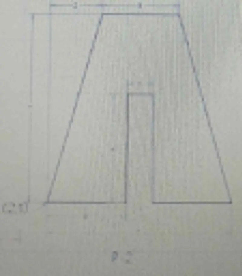
Procedure:-
Step1:-On the AutoCAD software set up the units to imperial template& decimal system 0.000
STEP2:-Set the limits in the command by using 'LIM' before drafting.
.STEPS OF CREATING IN AUTO CAD SOFTWARE BY ABSOLUTE COORDINATES SYSTEM:-
.Type the command 'L' for the line & specify the coordinates for starting point 1(2,1)
.Type the next coordinates of point 2(5,1) in the command box.
.Type the next coordinates of point 3(5,5) in the command box.
.Type the next coordinates of point 4(6,5) in the command box.
.Type the next coordinates of point 5(6,1) in the command box.
.Type the next coordinates of point 6(9,1) in the command box.
.Type the next coordinates of point 7(7,8) in the command box.
.Type the next coordinates of point 8(4,8) in the command box.
.Click close in the command box.
RESULT:-
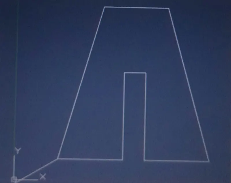
.STEPS OF CREATING IN AUTO CAD SOFTWARE BY RELATIVE RECTANGULAR COORDINATES SYSTEM:-
.Type the command 'L' for the line & specify the coordinates for starting point 1(2,1).
.Type the next coordinates of point 2@3,0 in the command box.
.Type the next coordinates of point 3@0,4 in the command box.
.Type the next coordinates of point 4@1,0 in the command box.
.Type the next coordinates of point 5@0,-4 in the command box.
.Type the next coordinates of point 6@3,0 in the command box.
.Type the next coordinates of point 7@-2,7 in the command box.
.Type the next coordinates of point 8@-3,0 in the command box.
.Click close on the command box.
RESULT:-
.STEPS OF CREATING IN AUTO CAD SOFTWARE BY RELATIVE POLAR COORDINATES SYSTEM:-
.Type the command 'L' for the line & specify the coordinates for starting point 1(2,1).
.Type the next coordinates of point 2@3<0 in the command box.
.Type the next coordinates of point 3@4<90 in the command box.
.Type the next coordinates of point 4@1<0 in the command box.
.Type the next coordinates of point 5@4<270 in the command box.
.Type the next coordinates of point 6@3<0 in the command box.
.Type the next coordinates of point 9@7<90 in the command box.
.Type the next coordinates of point 7@2<180 in the command box.
.Click close on the command box.
.Now use the command line 'L' & join point 6 & point 7 & then cancel the line command by pressing enter. & delete the line joining from point 6 to o9 & point 9 to 7.
.Type line command 'L' specify the point 7(7,8) & type the next coordinate of point 8@3<180 in the command box & then cancel the line command box & then cancel the line command by pressing enter.
.Now use the line command 'L' & join point 8 & point 1 & then cancel the line command by pressing enter.
RESULT:-
.STEPS OF CREATING IN AUTO CAD SOFTWARE BY DIRECT DISTANCE ENTRY SYSTEM:-
.Type the command 'L' for the line & specify the coordinates for starting point 1(2,1).
.Type the length 3 in the command box to +ve X axis for point 2.
.Type the length 4 in the command box to +ve Y axis for point 3.
.Type the length 1 in the command box to +ve X axis for point 4.
.Type the length 4 in the command box to -ve Y axis for point 5.
.Type the length 3 in the command box to +ve X axis for point 6.
.Type the length 7 in the command box to +ve Y axis for point 9.
.Type the length 2 in the command box to -ve X axis for point 7 & then cancel the line command by pressing enter.
.Now use the command line 'L' & join point 6 & point 7 & then cancel the line command by pressing enter. & delete the line joining from point 6 to 9 & point 9 to 7.
.Type line command 'L' specify the point 7(7,8) & type the length 3 in the command box to -ve X axis for point 8 & then cancel the line command by pressing enter.
.Now use the line command 'L' & join point 8 & point 1 & then cancel the line command by pressing enter.
RESULT:-
AIM:- To create geometry in Autocad using all the coordinates system methods.
Procedure:-
Step1:-On the AutoCAD software set up the units to imperial template& decimal system 0.000
STEP2:-Set the limits in the command by using 'LIM' before drafting.
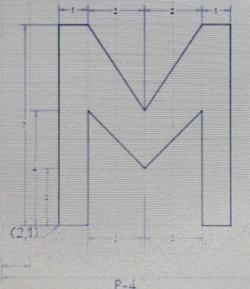
.STEPS OF CREATING IN AUTO CAD SOFTWARE BY ABSOLUTE COORDINATES SYSTEM:-
.Type the command 'L' for the line & specify the coordinates for starting point 1(2,1)
.Type the next coordinates of point 2(3,1) in the command box.
.Type the next coordinates of point 3(3,5) in the command box.
.Type the next coordinates of point 4(5,3) in the command box.
.Type the next coordinates of point 5(7,5) in the command box.
.Type the next coordinates of point 6(7,1) in the command box.
.Type the next coordinates of point 7(8,1) in the command box.
.Type the next coordinates of point 8(8,8) in the command box.
.Type the next coordinates of point 9(7,8) in the command box.
.Type the next coordinates of point 10(5,5) in the command box.
.Type the next coordinates of point 11(3,8) in the command box.
.Type the next coordinates of point 12(2,8) in the command box.
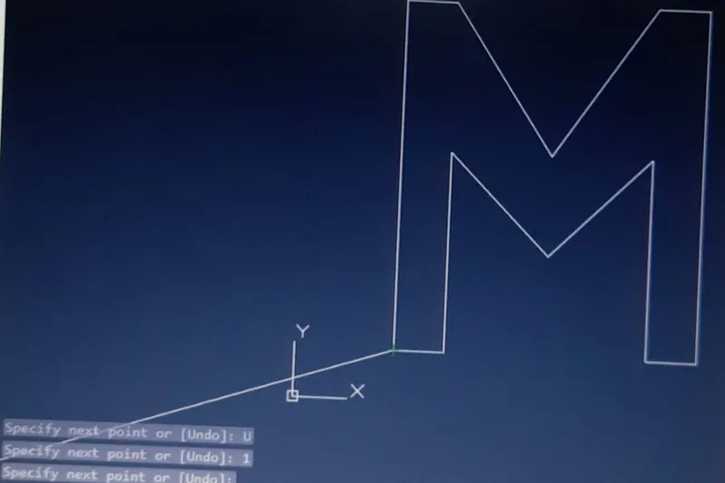
.Click close in the command box.
RESULT:-
.STEPS OF CREATING IN AUTO CAD SOFTWARE BY RELATIVE RECTANGULAR COORDINATES SYSTEM:-
.Type the command 'L' for the line & specify the coordinates for starting point 1(2,1).
.Type the next coordinates of point 2@1,0 in the command box.
.Type the next coordinates of point 3@0,4 in the command box.
.Type the next coordinates of point 4@2,-2 in the command box.
.Type the next coordinates of point 5@2,2 in the command box.
.Type the next coordinates of point 6@0,-4 in the command box.
.Type the next coordinates of point 7@1,0 in the command box.
.Type the next coordinates of point 8@0,7 in the command box.
.Type the next coordinates of point 9@-1,0 in the command box.
.Type the next coordinates of point 10@-2,-3 in the command box.
.Type the next coordinates of point 11@-2,3 in the command box.
.Type the next coordinates of point 12@-1,0 in the command box.
.Click close on the command box.
RESULT:-
.STEPS OF CREATING IN AUTO CAD SOFTWARE BY RELATIVE POLAR COORDINATES SYSTEM:-
.Type the command 'L' for the line & specify the coordinates for starting point 1(2,1).
.Type the next coordinates of point 2@1<0 in the command box.
.Type the next coordinates of point 3@4<90 in the command box.
.Type the next coordinates of point 10@2<0 in the command box.
.Type the next coordinates of point 4@2<270 in the command box.
.Cancel the line command by pressing enter.
.Now use the command line 'L' & join point 3 & point 4 & then cancel the line command by pressing enter. & delete the line joining from point 3 to 10 & point 10 to 4.
.Type line command 'L' specify the point 4(5,3) & type the next coordinate of point 10@2<90 in the command box.
.Type the next coordinates of point 5@2<0 in the command box.
.Cancel the line by pressing enter.
.Now use the command line 'L' & join point 4 & point 5 & then cancel the line command by pressing enter. & delete the line joining from point 4 to 10 & point 10 to 5.
.Type line command 'L' specify point 5(7,5) & type the next coordinate of point 6@4<270 in the command box.
.Type the next coordinates of point 7@1<0 in the command box.
.Type the next coordinates of point 8@7<90 in the command box.
.Type the next coordinates of point 9@1<180 in the command box.
.Type the next coordinates of point 5@3<270 in the command box.
.Type the next coordinates of point 10@2<180 in the command box.
.Cancel the line by pressing enter.
.Now use the command line 'L' & join point 9 & point 10 & then cancel the line command by pressing enter. & delete the line joining from point 9 to 5 & point 5 to 10.
.Type line command 'L' specify point 10(5,5) & type the next coordinate of point 3@2<180 in the command box.
.Type the next coordinates of point 11@3<90 in the command box.
.Cancel the line by pressing enter.
.Now use the command line 'L' & join point 10 & point 11 & then cancel the line command by pressing enter. & delete the line joining from point 10 to 3 & point 3 to 11.
.Type line command 'L' specify the point 11(3,8) & type the next coordinate of point 12@1<180 in the command box.
.Type the next coordinates of point 1@7<270 in the command box.
.Cancel the line by pressing enter.
RESULT:-
.STEPS OF CREATING IN AUTO CAD SOFTWARE BY DIRECT DISTANCE ENTRY SYSTEM:-
.Type the command 'L' for the line & specify the coordinates for starting point 1(2,1).
.Type the length 1 in the command box to +ve X axis for point 2.
.Type the length 4 in the command box to +ve Y axis for point 3.
.Type the length 2 in the command box to +ve X axis for point 10.
.Type the length 2 in the command box to -ve Y axis for point 4.
.Cancel the command by pressing enter & then type the command 'L' & join the points 3 & 4.
.Cancel the command by pressing enter & delete the other lines joining from point 3 to 10 & point 10 to 4.
.Type the command 'L' specify the start point 4(5,3) & type the length 2 in the command box +ve y-axis for point 10 & type the length 2 in the command box to +ve x-axis for point 5.
.Cancel the command by pressing enter & then type the command 'L' & join points 4 & 5.
.Cancel the line command by pressing enter & delete lines joining point 4 to 10 & point 10 to 5.
.Type the command 'L' specify the start point 5(7,5) 7 type the length 4 in command box to -ve y axis for point 6.
.Type the length 1 in the command box to +ve X axis for point 7.
.Type the length 7 in the command box to +ve Y axis for point 8.
.Type the length 1 in the command box to -ve X axis for point 9.
.Type the length 3 in the command box to -ve Y axis for point 5.
.Type the length 2 in the command box to -ve X axis for point 10.
.Cancel the line command by pressing enter
.Now use the command line 'L' & join point 9 & point 10 & then cancel the line command by pressing enter. & delete the line joining from point 9 to 5 & point 5 to 10.
.Type line command 'L' specify the point 10(5,5) & type the length 2 in the command box to -ve X axis for point 3 & type the length 3 in command box to +ve Y axis for point 11.
.Cancel the line command by pressing enter.
.Now use the command line 'L' & join point 10 & point 11 & then cancel the line command by pressing enter. & delete the line joining from point 10 to 3 & point 3 to 11.
.Type line command 'L' specify the point 11(3,8) & type the length 1 in the command box to -ve X axis for point 12 & type the length 7 in command box to -ve Y axis for point 1& then cancel the line command by pressing enter. .
.Click close on the command box
RESULT:-
AIM:- To create geometry in Autocad using all the coordinates system methods.
Procedure:-
Step1:-On the AutoCAD software set up the units to imperial template& decimal system 0.000
.STEP2:-Set the limits in the command by using 'LIM' before drafting.
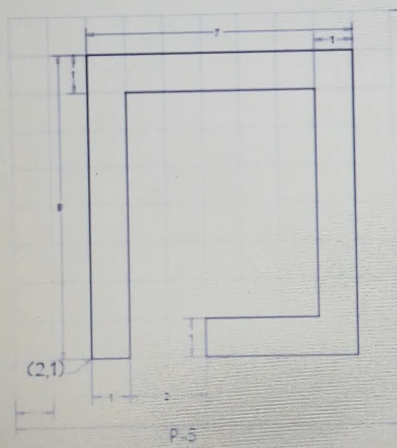
.STEPS OF CREATING IN AUTO CAD SOFTWARE BY ABSOLUTE COORDINATES SYSTEM:-
.Type the command 'L' for the line & specify the coordinates for starting point 1(2,1)
.Type the next coordinates of the point 2(3,1) in the command box.
.Type the next coordinates of the point 3(3,8) in the command box.
.Type the next coordinates of the point 4(8,8) in the command box.
.Type the next coordinates of the point 5(8,2) in the command box.
.Type the next coordinates of the point 6(5,2) in the command box.
.Type the next coordinates of the point 7(5,1) in the command box.
.Type the next coordinates of the point 8(9,1) in the command box.
.Type the next coordinates of the point 9(9,9) in the command box.
.Type the next coordinates of the point 10(2,9) in the command box.
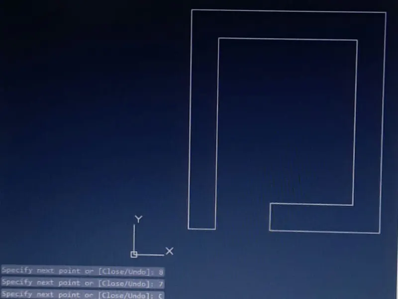
.Click close in the command box.
RESULT:-
.STEPS OF CREATING IN AUTO CAD SOFTWARE BY RELATIVE RECTANGULAR COORDINATES SYSTEM:-
.Type the command 'L' for the line & specify the coordinates for starting point 1(2,1).
.Type the next coordinates of point 2@1,0 in the command box.
.Type the next coordinates of point 3@0,7 in the command box.
.Type the next coordinates of point 4@5,0 in the command box.
.Type the next coordinates of point 5@0,-6 in the command box.
.Type the next coordinates of point 6@-3,0 in the command box.
.Type the next coordinates of point 7@0,-1 in the command box.
.Type the next coordinates of point 8@4,0 in the command box.
.Type the next coordinates of point 9@0,8 in the command box.
.Type the next coordinates of point 10@-7,0 in the command box.
.Click close on the command box.
RESULT:-
.STEPS OF CREATING IN AUTO CAD SOFTWARE BY RELATIVE POLAR COORDINATES SYSTEM:-
.Type the command 'L' for the line & specify the coordinates for starting point 1(2,1).
.Type the next coordinates of point 2@1<0 in the command box.
.Type the next coordinates of point 3@7<90 in the command box.
.Type the next coordinates of point 4@5<0 in the command box.
.Type the next coordinates of point 5@6<270 in the command box.
.Type the next coordinates of point 6@3<180 in the command box.
.Type the next coordinates of point 7@1<270 in the command box.
.Type the next coordinates of point 8@4<0 in the command box.
.Type the next coordinates of point 9@8<90 in the command box.
.Type the next coordinates of point 10@7<180 in the command box.
.Click close on the command box.
RESULT:-
.STEPS OF CREATING IN AUTO CAD SOFTWARE BY DIRECT DISTANCE ENTRY SYSTEM:-
.Type the command 'L' for the line & specify the coordinates for starting point 1(2,1).
.Type the length 1 in the command box to +ve X axis for point 2.
.Type the length 7 in the command box to +ve Y axis for point 3.
.Type the length 5 in the command box to +ve X axis for point 4.
.Type the length 6 in the command box to -ve Y axis for point 5.
.Type the length 3 in the command box to -ve X axis for point 6.
.Type the length 1 in the command box to -ve Y axis for point 7.
.Type the length 4 in the command box to +ve X axis for point 8.
.Type the length 8 in the command box to +ve Y axis for point 9.
.Type the length 7 in the command box to -ve X axis for point 10.
.Click close on the command box.
RESULT:-
AIM:- To create geometry in Autocad using all the coordinates system methods.
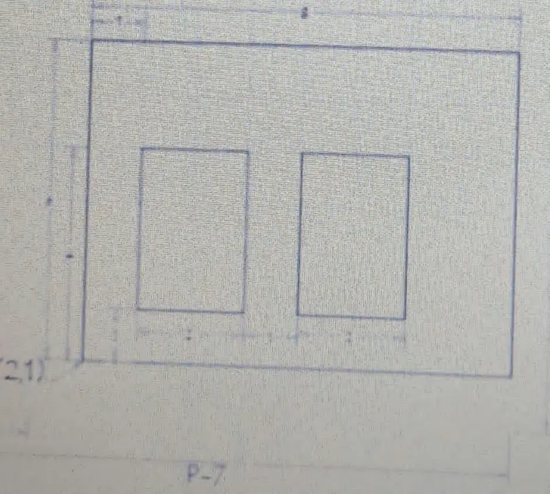
Procedure:-
Step1:-On the AutoCAD software set up the units to imperial template& decimal system 0.000
.STEP2:-Set the limits in the command by using 'LIM' before drafting.
.STEPS OF CREATING IN AUTO CAD SOFTWARE BY ABSOLUTE COORDINATES SYSTEM:-
.Type the command 'L' for the line & specify the coordinates for starting point 1(2,1)
.Type the next coordinates of the point 2(10,1) in the command box.
.Type the next coordinates of the point 3(10,7) in the command box.
.Type the next coordinates of the point 4(2,7) in the command box.
.Click close on the command box.
.Type the command 'L' for the line & specify the coordinate for point 5(3,2).
.Type the next coordinates of the point 6(5,2) in the command box.
.Type the next coordinates of the point 7(5,5) in the command box.
.Type the next coordinates of the point 8(3,5) in the command box.
.Click close on the command box.
.Type the command 'L' for the line & specify the coordinate for point 9(6,2).
.Type the next coordinates of the point 10(8,2) in the command box.
.Type the next coordinates of the point 11(8,5) in the command box.
.Type the next coordinates of the point 12(6,5) in the command box.
.Click close in the command box.
RESULT:-
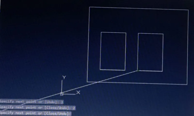
.STEPS OF CREATING IN AUTO CAD SOFTWARE BY RELATIVE RECTANGULAR COORDINATES SYSTEM:-
.Type the command 'L' for the line & specify the coordinates for starting point 1(2,1).
.Type the next coordinates of point 2@8,0 in the command box.
.Type the next coordinates of point 3@0,6 in the command box.
.Type the next coordinates of point 4@-8,0 in the command box.
.Click close in the command box.
.Type the command 'L' for the line & specify the coordinate for point 5(3,2).
.Type the next coordinates of point 6@2,0 in the command box.
.Type the next coordinates of point 7@0,3 in the command box.
.Type the next coordinates of point 8@-2,0 in the command box.
.Click close on the command box.
.Type the command 'L' for the line & specify the coordinate for point 9(6,2).
.Type the next coordinates of point 10@2,0 in the command box.
.Type the next coordinates of point 11@0,3 in the command box.
.Type the next coordinates of point 12@-2,0 in the command box.
.Click close on the command box.
RESULT:-
.STEPS OF CREATING IN AUTO CAD SOFTWARE BY RELATIVE POLAR COORDINATES SYSTEM:-
.Type the command 'L' for the line & specify the coordinates for starting point 1(2,1).
.Type the next coordinates of point 2@8<0 in the command box.
.Type the next coordinates of point 3@6<90 in the command box.
.Type the next coordinates of point 4@8<180 in the command box.
.Click close in the command box.
.Type the command 'L' for the line & specify the coordinate for point 5(3,2).
.Type the next coordinates of point 6@2<0 in the command box.
.Type the next coordinates of point 7@3<90 in the command box.
.Type the next coordinates of point 7@1<270 in the command box.
.Type the next coordinates of point 8@2<180 in the command box.
.Click close on the command box.
.Type the command 'L' for the line & specify the coordinate for point 9(6,2).
.Type the next coordinates of point 10@2<0 in the command box.
.Type the next coordinates of point 11@3<90 in the command box.
.Type the next coordinates of point 12@2<180 in the command box.
.Click close on the command box.
RESULT:-
.STEPS OF CREATING IN AUTO CAD SOFTWARE BY DIRECT DISTANCE ENTRY SYSTEM:-
.Type the command 'L' for the line & specify the coordinates for starting point 1(2,1).
.Type the length 8 in the command box to +ve X axis for point 2.
.Type the length 6 in the command box to +ve Y axis for point 3.
.Type the length 8 in the command box to -ve X axis for point 4.
.Click close in the command box.
.Type the command 'L' for the line & specify the coordinate for point 5(3,2).
.Type the length 2 in the command box to +ve Y axis for point 6.
.Type the length 3 in the command box to +ve Y axis for point 7.
.Type the length 2 in the command box to -ve X axis for point 8.
.Click close on the command box.
.Type the command 'L' for the line & specify the coordinate for point 9(6,2).
.Type the length 2 in the command box to +ve X axis for point 10.
.Type the length 3 in the command box to +ve Y axis for point 11.
.Type the length 2 in the command box to -ve X axis for point 12.
.Click close on the command box.
RESULT:-
AIM:- To create geometry in Autocad using all the coordinates system methods.
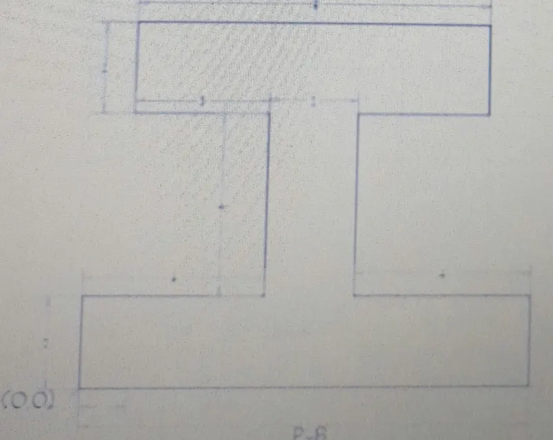
Procedure:-
Step1:-On the AutoCAD software set up the units to imperial template& decimal system 0.000
.STEP2:-Set the limits in the command by using 'LIM' before drafting.
.STEPS OF CREATING IN AUTO CAD SOFTWARE BY ABSOLUTE COORDINATES SYSTEM:-
.Type the command 'L' for the line & specify the coordinates for starting point 1(0,0)
.Type the next coordinates of the point 2(10,0) in the command box.
.Type the next coordinates of the point 3(10,2) in the command box.
.Type the next coordinates of the point 4(6,2) in the command box.
.Type the next coordinates of the point 5(6,6) in the command box.
.Type the next coordinates of the point 6(9,6) in the command box.
.Type the next coordinates of the point 7(9,8) in the command box.
.Type the next coordinates of the point 8(1,8) in the command box.
.Type the next coordinates of the point 9(1,6) in the command box.
.Type the next coordinates of the point 10(4,6) in the command box.
.Type the next coordinates of the point 11(4,2) in the command box.
.Type the next coordinates of the point 12(0,2) in the command box.
.Click close on the command box.
RESULT:-
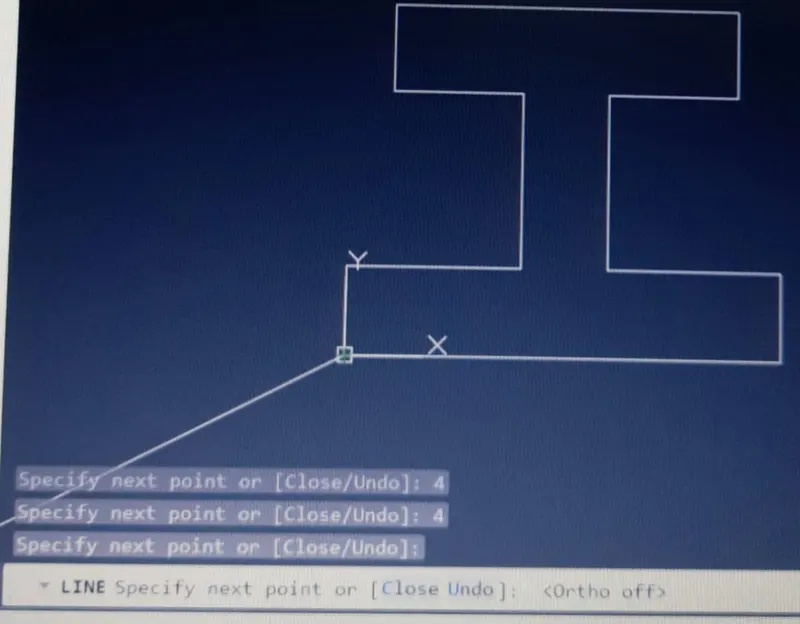
.STEPS OF CREATING IN AUTO CAD SOFTWARE BY RELATIVE RECTANGULAR COORDINATES SYSTEM:-
.Type the command 'L' for the line & specify the coordinates for starting point 1(0,0).
.Type the next coordinates of point 2@10,0 in the command box.
.Type the next coordinates of point 3@0,2 in the command box.
.Type the next coordinates of point 4@-4,0 in the command box.
.Type the next coordinates of point 5@0,4 in the command box.
.Type the next coordinates of point 6@3,0 in the command box.
.Type the next coordinates of point 7@0,2 in the command box.
.Type the next coordinates of point 8@-8,0 in the command box.
.Type the next coordinates of point 9@0,-2 in the command box.
.Type the next coordinates of point 10@3,0 in the command box.
.Type the next coordinates of point 11@0,-4 in the command box.
.Type the next coordinates of point 12@-4,0 in the command box.
.Click close on the command box.
RESULT:-
.STEPS OF CREATING IN AUTO CAD SOFTWARE BY RELATIVE POLAR COORDINATES SYSTEM:-
.Type the command 'L' for the line & specify the coordinates for starting point 1(0,0).
.Type the next coordinates of point 2@10<0 in the command box.
.Type the next coordinates of point 3@2<90 in the command box.
.Type the next coordinates of point 4@4<180 in the command box.
.Type the next coordinates of point 5@4<90 in the command box.
.Type the next coordinates of point 6@3<0 in the command box.
.Type the next coordinates of point 7@2<90 in the command box.
.Type the next coordinates of point 8@8<180 in the command box.
.Type the next coordinates of point 9@2<270 in the command box.
.Type the next coordinates of point 10@3<0 in the command box.
.Type the next coordinates of point 11@4<270 in the command box.
.Click close on the command box.
RESULT:-
.STEPS OF CREATING IN AUTO CAD SOFTWARE BY DIRECT DISTANCE ENTRY SYSTEM:-
.Type the command 'L' for the line & specify the coordinates for starting point 1(0,0).
.Type the length 10 in the command box to +ve X axis for point 2.
.Type the length 2 in the command box to +ve Y axis for point 3.
.Type the length 4 in the command box to -ve X axis for point 4.
.Type the length 4 in the command box to +ve Y axis for point 5.
.Type the length 3 in the command box to +ve X axis for point 5.
.Type the length 3 in the command box to +ve X axis for point 6.
.Type the length 2 in the command box to +ve Y axis for point 7.
.Type the length 8 in the command box to -ve X axis for point 8.
.Type the length 2 in the command box to -ve Y axis for point 9.
.Type the length 3 in the command box to +ve X axis for point 10.
.Type the length 4 in the command box to -ve Y axis for point 11.
.Type the length 4 in the command box to -ve X axis for point 12.
.Click close on the command box.
RESULT:-
AIM:- To create geometry in Autocad using all the coordinates system methods.
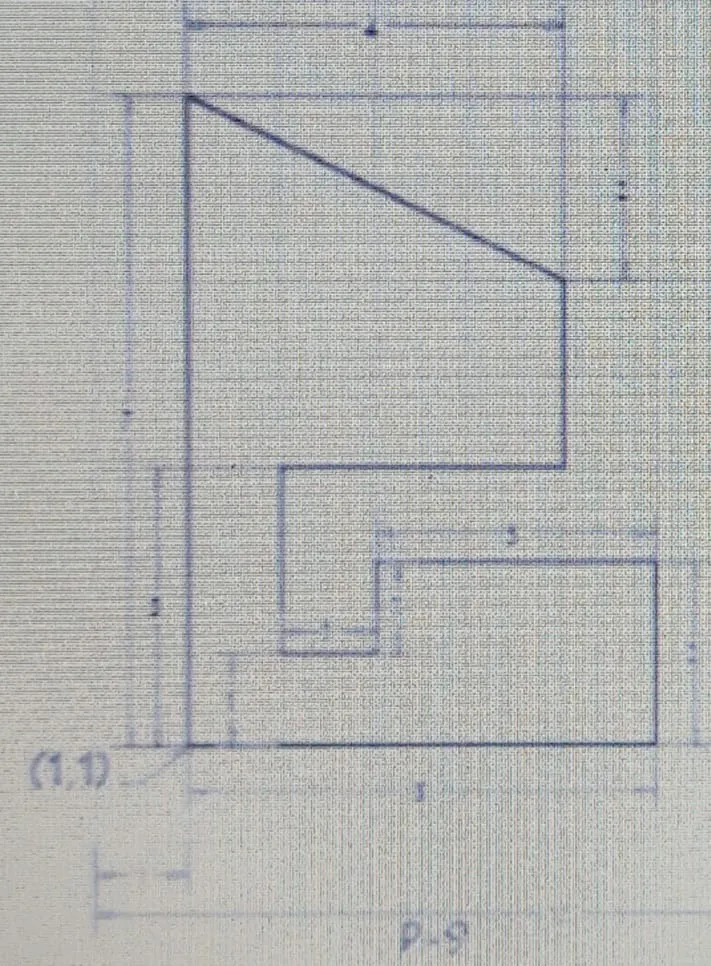
Procedure:-
Step1:-On the AutoCAD software set up the units to imperial template& decimal system 0.000
.STEP2:-Set the limits in the command by using 'LIM' before drafting.
.STEPS OF CREATING IN AUTO CAD SOFTWARE BY ABSOLUTE COORDINATES SYSTEM:-
.Type the command 'L' for the line & specify the coordinates for starting point 1(1,1)
.Type the next coordinates of the point 2(6,1) in the command box.
.Type the next coordinates of the point 3(6,3) in the command box.
.Type the next coordinates of the point 4(3,3) in the command box.
.Type the next coordinates of the point 5(3,2) in the command box.
.Type the next coordinates of the point 6(2,2) in the command box.
.Type the next coordinates of the point 7(2,4) in the command box.
.Type the next coordinates of the point 8(5,4) in the command box.
.Type the next coordinates of the point 9(5,6) in the command box.
.Type the next coordinates of the point 10(1,8) in the command box.
.Click close on the command box.
RESULT:-

.STEPS OF CREATING IN AUTO CAD SOFTWARE BY RELATIVE RECTANGULAR COORDINATES SYSTEM:-
.Type the command 'L' for the line & specify the coordinates for starting point 1(1,1).
.Type the next coordinates of point 2@5,0 in the command box.
.Type the next coordinates of point 3@0,2 in the command box.
.Type the next coordinates of point 4@-3,0 in the command box.
.Type the next coordinates of point 5@0,-1 in the command box.
.Type the next coordinates of point 6@-1,0 in the command box.
.Type the next coordinates of point 7@0,2 in the command box.
.Type the next coordinates of point 8@3,0 in the command box.
.Type the next coordinates of point 9@0,2 in the command box.
.Type the next coordinates of point 10@-4,2 in the command box.
.Click close on the command box.
RESULT:-
.STEPS OF CREATING IN AUTO CAD SOFTWARE BY RELATIVE POLAR COORDINATES SYSTEM:-
.Type the command 'L' for the line & specify the coordinates for starting point 1(0,0).
.Type the next coordinates of point 2@5<0 in the command box.
.Type the next coordinates of point 3@2<90 in the command box.
.Type the next coordinates of point 4@3<180 in the command box.
.Type the next coordinates of point 5@1<270 in the command box.
.Type the next coordinates of point 6@1<180 in the command box.
.Type the next coordinates of point 7@2<90 in the command box.
.Type the next coordinates of point 8@3<0 in the command box.
.Type the next coordinates of point 9@2<90 in the command box.
.Type the next coordinates of point 11@2<90 in the command box.
.Type the next coordinates of point 10@4<180 in the command box.
.Cancel the line by pressing enter.
.Now use the command line 'L' & join point 9 & point 10 & then cancel the line command by pressing enter. & delete the line joining from point 9 to 10 & point 10 to 11.
.Type line command 'L' specify point 10(1,8) & type the next coordinate of point 1@7<270 in the command box.
.Cancel the line by pressing enter.
RESULT:-
.STEPS OF CREATING IN AUTO CAD SOFTWARE BY DIRECT DISTANCE ENTRY SYSTEM:-
.Type the command 'L' for the line & specify the coordinates for starting point 1(1,1).
.Type the length 5 in the command box to +ve X axis for point 2.
.Type the length 2 in the command box to +ve Y axis for point 3.
.Type the length 3 in the command box to -ve X axis for point 4.
.Type the length 1 in the command box to -ve Y axis for point 5.
.Type the length 1 in the command box to -ve X axis for point 6.
.Type the length 3 in the command box to +ve X axis for point 7.
.Type the length 2 in the command box to +ve X axis for point 8.
.Type the length 2 in the command box to +ve X axis for point 9.
.Delete the line joining from point 9 to 10 & point 10 to 11.
.Cancel the line command by pressing enter.
RESULT:-
AIM:- To create geometry in Autocad using all the coordinates system methods.
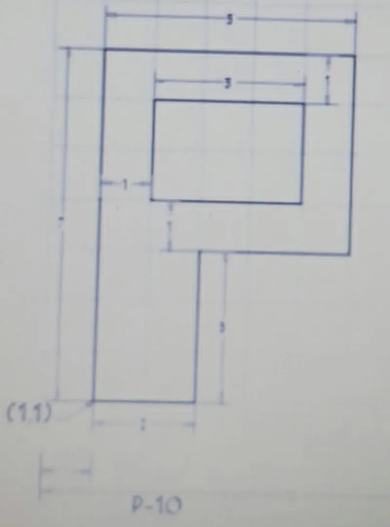
Procedure:-
Step1:-On the AutoCAD software set up the units to imperial template& decimal system 0.000
.STEP2:-Set the limits in the command by using 'LIM' before drafting.
.STEPS OF CREATING IN AUTO CAD SOFTWARE BY ABSOLUTE COORDINATES SYSTEM:-
.Type the command 'L' for the line & specify the coordinates for starting point 1(1,1)
.Type the next coordinates of the point 2(3,1) in the command box.
.Type the next coordinates of the point 3(3,4) in the command box.
.Type the next coordinates of point 4(6,4) in the command box.
.Type the next coordinates of the point 5(6,8) in the command box.
.Type the next coordinates of the point 6(1,8) in the command box.
.Click close on the command box.
.Type the command 'L' for the line & specify the coordinate for point 7(2,5).
.Type the next coordinates of the point 8(5,5) in the command box.
.Type the next coordinates of the point 9(5,7) in the command box.
.Type the next coordinates of the point 10(2,7) in the command box.
.Click close on the command box.
RESULT:-
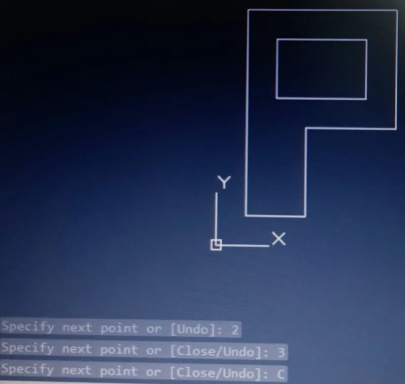
.STEPS OF CREATING IN AUTO CAD SOFTWARE BY RELATIVE RECTANGULAR COORDINATES SYSTEM:-
.Type the command 'L' for the line & specify the coordinates for starting point 1(1,1).
.Type the next coordinates of point 2@2,0 in the command box.
.Type the next coordinates of point 3@0,3 in the command box.
.Type the next coordinates of point 4@3,0 in the command box.
.Type the next coordinates of point 5@0,4 in the command box.
.Type the next coordinates of point 6@-5,0 in the command box.
.Click close on the command box.
.Type the command 'L' for the line & specify the coordinate for point 7(2,5).
.Type the next coordinates of point 8@3,0 in the command box.
.Type the next coordinates of point 9@0,2 in the command box.
.Type the next coordinates of point 10@-3,0 in the command box.
.Click close on the command box.
RESULT:-
.STEPS OF CREATING IN AUTO CAD SOFTWARE BY RELATIVE POLAR COORDINATES SYSTEM:-
.Type the command 'L' for the line & specify the coordinates for starting point 1(1,1).
.Type the next coordinates of point 2@2<0 in the command box.
.Type the next coordinates of point 3@3<90 in the command box.
.Type the next coordinates of point 4@3<0 in the command box.
.Type the next coordinates of point 5@4<90 in the command box.
.Type the next coordinates of point 6@5<180 in the command box.
.Click close on the command box.
.Type the command 'L' for the line & specify the coordinate for point 7(2,5).
.Type the next coordinates of point 8@3<0 in the command box.
.Type the next coordinates of point 9@2<90 in the command box.
.Type the next coordinates of point 10@3<180 in the command box.
.Click close on the command box.
RESULT:-
.STEPS OF CREATING IN AUTO CAD SOFTWARE BY DIRECT DISTANCE ENTRY SYSTEM:-
.Type the command 'L' for the line & specify the coordinates for starting point 1(1,1).
.Type the length 2 in the command box to +ve X axis for point 2.
.Type the length 3 in the command box to +ve Y axis for point 3.
.Type the length 3 in the command box to +ve X axis for point 4.
.Type the length 4 in the command box to +ve Y axis for point 5.
.Type the length 5 in the command box to -ve X axis for point 6.
.Click close on the command box.
.Type the command 'L' for the line & specify the coordinate for point 7(2,5).
.Type the length 3 in the command box to +ve X axis for point 8.
.Type the length 2 in the command box to +ve Y axis for point 9.
.Type the length 3 in the command box to -ve X axis for point 10.
.Click close on the command box.
RESULT:-
AIM:- To create geometry in Autocad using all the coordinates system methods.

Procedure:-
Step1:-On the AutoCAD software set up the units to imperial template& decimal system 0.000
.STEP2:-Set the limits in the command by using 'LIM' before drafting.
.STEPS OF CREATING IN AUTO CAD SOFTWARE BY ABSOLUTE COORDINATES SYSTEM:-
.Type the command 'L' for the line & specify the coordinates for starting point 1(1,1)
.Type the next coordinates of the point 2(10,0) in the command box.
.Type the next coordinates of the point 3(10,1) in the command box.
.Type the next coordinates of point 4(8,1) in the command box.
.Type the next coordinates of the point 5(8,5) in the command box.
.Type the next coordinates of the point 6(10,5) in the command box.
.Type the next coordinates of the point 7(10,6) in the command box.
.Type the next coordinates of the point 8(5,9) in the command box.
.Type the next coordinates of the point 9(0,6) in the command box.
.Type the next coordinates of the point 10(2,6) in the command box.
.Type the next coordinates of the point 11(2,1) in the command box.
.Type the next coordinates of the point 12(0,1) in the command box.
.Click close on the command box.
.Type the command 'C' for the circle & specify the coordinate of center of circle as point 13(5,4).
.Type the radius radious 2 in the command box & press enter.
RESULT:-
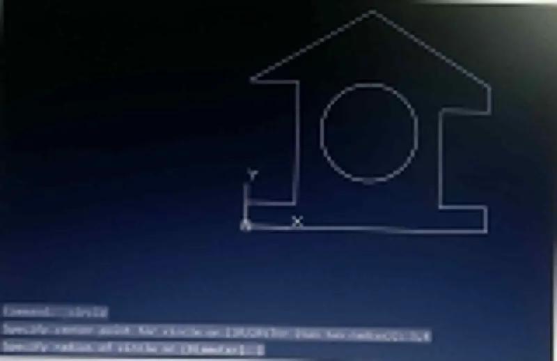
.STEPS OF CREATING IN AUTO CAD SOFTWARE BY RELATIVE RECTANGULAR COORDINATES SYSTEM:-
.Type the command 'L' for the line & specify the coordinates for starting point 1(1,1).
.Type the next coordinates of point 2@10,0 in the command box.
.Type the next coordinates of point 3@0,1 in the command box.
.Type the next coordinates of point 4@-2,0 in the command box.
.Type the next coordinates of point 5@0,4 in the command box.
.Type the next coordinates of point 6@2,0 in the
.Type the next coordinates of point 7@0,1 in the command box.
.Type the next coordinates of point 8@-5,3 in the command box.
.Type the next cordinates of point 10@2,0 in the command box.
.Type the next coordinates of point 11@0,-5 in the command box.
.Type the next cordinates of point 12@-2,0 in the command box.
.Click close on the command box.
.Type the command 'C' for the circle & specify the coordinate of center of circle as point 13(5,4).
.Type the radius radious 2 in the command box & press enter.
RESULT:-
.STEPS OF CREATING IN AUTO CAD SOFTWARE BY RELATIVE POLAR COORDINATES SYSTEM:-
.Type the command 'L' for the line & specify the coordinates for starting point 1(1,1).
.Type the next coordinates of point 2@10<0 in the command box.
.Type the next coordinates of point 3@1<90 in the command box.
.Type the next coordinates of point 4@2<180 in the command box.
.Type the next coordinates of point 5@4<90 in the command box.
.Type the next coordinates of point 6@2<0 in the command box.
.Type the next coordinates of point 7@1<90 in the command box.
.Type the next coordinates of point 14@3<90 in the command box.
.Type the next coordinates of point 8@5<180 in the command box.
.Cancel the command by pressing enter.
.Now use line command 'L' & join point 7 & point 8 & then cancel the command by pressing enter.
.Delete lines joining from point 7 to 14 & point 14 to 8.
.Type command 'L' & join point 8 & point 9 & then cancel the command by pressing enter.
.Delete lines joining from point 8 to 15 & point 15 to 9.
.Type the command 'L' specify the start point 9(0,6) & type the next coordinate point 10@2<0 in the command box.
.Type the next coordinates of point 11@5<270 in the command box.
.Type the next coordinates of point 12@2<180 in the command box.
.Click close on the command box.
.Type the command 'C' for the circle & specify the coordinate of the center of circle as point 13(5,4).
.Type the radius radious 2 in the command box & press enter.
RESULT:-
.STEPS OF CREATING IN AUTO CAD SOFTWARE BY DIRECT DISTANCE ENTRY SYSTEM:-
.Type the command 'L' for the line & specify the coordinates for starting point 1(0,0).
.Type the length 10 in the command box to +ve X axis for point 2.
.Type the length 1 in the command box to +ve Y axis for point 3.
.Type the length 2 in the command box to -ve X axis for point 4.
.Type the length 4 in the command box to +ve Y axis for point 5.
.Type the length 2 in the command box to +ve X axis for point 6.
.Type the length 1 in the command box to +ve Y axis for point 7.
.Type the length 3 in the command box to +ve Y axis for point 14.
.Type the length 5 in the command box to -ve Y-axis for point 8.
.Cancel the command by pressing enter & again type line command & then join points 7 & 8.
.Delete the other lines joining pointing 7&8.
.Type the length 5 in the command box to -ve Y axis for point 11.
.Type the length 2 in the command box to -ve X axis for point 12.
.Type the length 1 in the command box to -ve Y axis for point 1 & cancel by pressing enter..
.Type the command 'C' for the circle & specify the coordinate of the center of circle as point 13(5,4).
.Type the radius radious 2 in the command box & press enter.
RESULT:-
AIM:- To create geometry in Autocad using all the coordinates system methods.
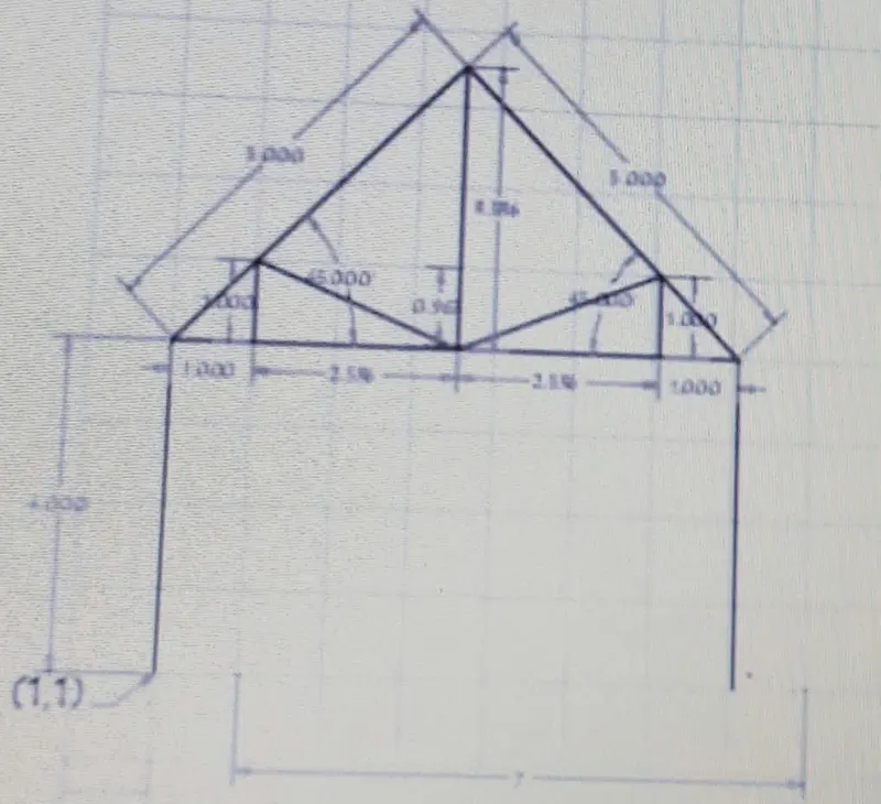
Procedure:-
Step1:-On the AutoCAD software set up the units to imperial template& decimal system 0.000
.STEP2:-Set the limits in the command by using 'LIM' before drafting.
.STEPS OF CREATING IN AUTO CAD SOFTWARE BY ABSOLUTE COORDINATES SYSTEM:-
.Type the command 'L' for the line & specify the coordinates for starting point 1(1,1)
.Type the next coordinates of the point 2(1,5) in the command box.
.Type the next coordinates of the point 3(4.5,8.5) in the command box.
.Type the next coordinates of point 4(8,5) in the command box.
.Type the next coordinates of the point 5(8,1) in the command box.
.Cancel the command by pressing enter.
.Type the command 'L' for the line & join point 2& point 4 & then cancel the line command by pressing enter.
.Type the command 'L' for the line type the next coordinate of point 6(4.5,5) in the command box.
.Type the next coordinates of the point 7(2,6) in the command box.
.Type the next coordinates of the point 8(2,5) in the command box.
.Cancel the command by pressing enter.
.Type the command 'L' for the line type the next coordinate of point 6(4.5,5) in the command box.
.Type the next coordinates of the point 9(7,6) in the command box.
.Type the next coordinates of the point 10(7,5) in the command box.
.Cancel the command by pressing enter.
.Type the command 'L' for the line & join point 6 & point 3 & then cancel the line command by pressing enter.
RESULT:-
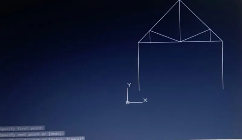
.STEPS OF CREATING IN AUTO CAD SOFTWARE BY RELATIVE RECTANGULAR COORDINATES SYSTEM:-
.Type the command 'L' for the line & specify the coordinates for starting point 1(1,1).
.Type the next coordinates of point 2@0,4 in the command box.
.Type the next coordinates of point [email protected],3.5 in the command box.
.Type the next coordinates of point [email protected],-3.5 in the command box.
.Type the next coordinates of point 5@0,-4 in the command box.
.Cancel the command by pressing enter.
.Type the command 'L' for the line & join point 2 & point 4 & then cancel the line command by pressing enter.
.Type the command 'L' for the line type the next coordinate of point 6(4.5,5) in the command box.
.Type the next coordinates of point [email protected],1 in the command box.
.Type the next coordinates of point 8@0,-1 in the command box
.Cancel the command by pressing enter.
.Type the command 'L' for the line type the next coordinate of point 6(4.5,5) in the command box.
.Type the next coordinates of point [email protected],1 in the command box.
.Type the next coordinates of point 10@0,-1 in the command box.
.Cancel the command by pressing enter.
.Type the command 'L' for the line & join point 6 & point 3 & then cancel the line command by pressing enter.
RESULT:-
.STEPS OF CREATING IN AUTO CAD SOFTWARE BY RELATIVE POLAR COORDINATES SYSTEM:-
.Type the command 'L' for the line & specify the coordinates for starting point 1(1,1).
.Type the next coordinates of point 2@4<90 in the command box.
.Type the next coordinates of point 3@5<45 in the command box.
.Type the next coordinates of point 4@5<315 in the command box.
.Type the next coordinates of point 5@4<270 in the command box.
.Cancel the command by pressing enter.
.Type the command 'L' for the line & join point 2 & point 4 & then cancel the line command by pressing enter.
.Type the command 'L' for the line type the next coordinate of point 3(4.5,8.5) in the command box.
.Type the next coordinates of point [email protected]<270 in the command box & then cancel the line command by pressing enter.
.Type the command 'L' for the line type the next coordinate of point 7(2,6) in the command box.
.Type the next coordinates of point 8@1<270 in the command box.
.Cancel the command by pressing enter.
.Type the command 'L' for the line & join point 7 & point 6 & then cancel the line command by pressing enter.
.Type the command 'L' for the line type the next coordinate of point 9(7,6) in the command box.
.Type the next coordinates of point 10@1<270 in the command box.
.Cancel the line by pressing enter.
.Type the command 'L' for the line & join point 9 & point 6 & then cancel the line command by pressing enter.
RESULT:-
.STEPS OF CREATING IN AUTO CAD SOFTWARE BY DIRECT DISTANCE ENTRY SYSTEM:-
.Type the command 'L' for the line & specify the coordinates for starting point 1(1,1).
.Type the length 4 in the command box to +ve y axis for point 2.
.Type the length 7 in the command box to +ve X axis for point 4.
.Type the length 4 in the command box to -ve Y axis for point 5.
.Cancel the line by pressing enter.
.Type the command 'L' for the line type the next coordinate of point 6(4.5,5) in the command box.
.Type the length 3.5 in the command box to +ve Y axis for point 3.
.Cancel the command by pressing enter & again type line command 'L' & then join point 3 & point 2.
.Cancel the command by pressing enter & again type line command 'L' & then join point 3 & point 4 & press enter.
.Type the command 'L' for the line & specify the coordinate for point 7(2,6).
.Type the length 1 in the command box to -ve Y axis for point 10 & press enter.
.Cancel the command by pressing enter & again type line command 'L' & then join point 6 & point 7 & press enter.
.Cancel the command by pressing enter & again type line command 'L' & then join point 6 & point 9 & press enter.
RESULT:-
AIM:- To create geometry in Autocad using all the coordinates system methods.
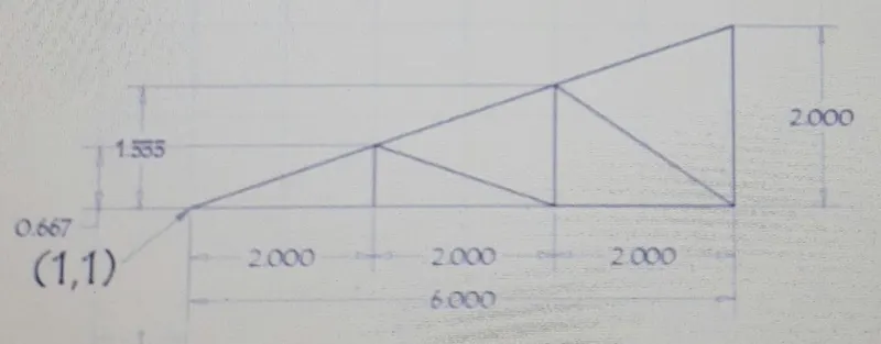
Procedure:-
.Step1:-On the AutoCAD software set up the units to imperial template& decimal system 0.000
.STEP2:-Set the limits in the command by using 'LIM' before drafting.
.STEPS OF CREATING IN AUTO CAD SOFTWARE BY ABSOLUTE COORDINATES SYSTEM:-
.Type the command 'L' for the line & specify the coordinates for starting point 1(1,1)
.Type the next coordinates of the point 2(7,1) in the command box.
.Type the next coordinates of the point 3(7,3) in the command box.
.Click close on the command box.
.Cancel the line by pressing enter.
.Type the command 'L' for the line type the next coordinate of point 4(3,1).
.Type the next coordinates of point 6(3,1.667) in the command box.
.Type the next coordinates of the point 5(5,1) in the command box.
.Type the next coordinates of the point 7(5,2.333) in the command box.
.Cancel the command by pressing enter.
.Type the command 'L' for the line & join point 7 & point 2 & press enter.
RESULT:-
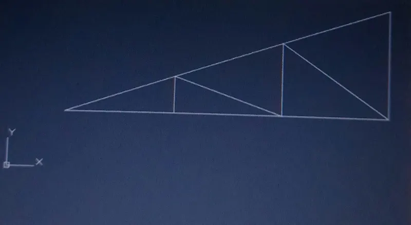
.STEPS OF CREATING IN AUTO CAD SOFTWARE BY RELATIVE RECTANGULAR COORDINATES SYSTEM:-
.Type the command 'L' for the line & specify the coordinates for starting point 1(1,1).
.Type the next coordinates of point 2@6,0 in the command box.
.Type the next coordinates of point 3@0,2 in the command box.
.Click close on the command box & cancel by pressing enter.
.Type the command 'L' for the line type the next coordinate of point 4(3,1) in the command box
.Type the next coordinates of point 6@0,0.667 in the command box.
.Type the next coordinates of point 5@2,-0.667 in the command box.
.Type the next coordinates of point 7@0,1.333 in the command box.
.Cancel the command by pressing enter.
.Type the command 'L' for the line & join point 7 & point 2 & press enter.
RESULT:-
.STEPS OF CREATING IN AUTO CAD SOFTWARE BY RELATIVE POLAR COORDINATES SYSTEM:-
.Type the command 'L' for the line & specify the coordinates for starting point 1(1,1).
.Type the next coordinates of point 2@6<0 in the command box.
.Type the next coordinates of point 3@2<90 in the command box.
.Click close on the command box & cancel by pressing enter.
.Type the command 'L' for the line type the next coordinate of point 4(3,1) in the command box.
.Type the next coordinates of point [email protected]<90 in the command box & cancel the line command by pressing enter.
.Type the command 'L' for the line type the next coordinate of point 5(5,1) in the command box.
.Type the next coordinates of point 7@1.333<90 in the command box & cancel the line command by pressing enter.
.Type the command 'L' for the line & join point 6 & point 5 & press enter.
.Type the command 'L' for the line & join point 7 & point 2 & press enter.
RESULT:-
.STEPS OF CREATING IN AUTO CAD SOFTWARE BY DIRECT DISTANCE ENTRY SYSTEM:-
.Type the command 'L' for the line & specify the coordinates for starting point 1(1,1).
.Type the length 6 in the command box to +ve X axis for point 2.
.Type the length 2 in the command box to +ve Y axis for point 4.
.Type the length 4 in the command box to -ve Y axis for point 3.
.Click close on the command box & Cancel the line by pressing enter.
.Type the command 'L' for the line type the next coordinate of point 4(3,1).
.Type the length 0.667 in the command box to +ve Y axis for point 6 & Cancel the command by pressing enter.
.Type the command 'L' for the line type the next coordinate of point 5(5,1).
.Type the length 1.333 in the command box to +ve Y axis for point 6 & cancel the line command by pressing enter.
.Cancel the command by pressing enter & again type line command 'L' & then join point 6 & point 5 & press enter.
.Cancel the command by pressing enter & again type line command 'L' & then join point 7 & point 2 & press enter.
RESULT:-