Creation of geometries by Coordinate system methods using AutoCad
1) AIM: To provide the given diagram in P-1 by AutoCAD, and draw the diagram with following Dimensions using Imperial Template and Decimal Unit.
Procedure:
- Command Line in the command box/ From menu bar line can be chosen.
- 1st point as 2,1
- 2nd point as 8,1
- 3rd point as 8,2
- 4th point as 3,2
- 5th point as 3,6
- 6th point as 8,6
- 7th point as 8,7
- 8th point as 2,7
- Close command / 2,1.
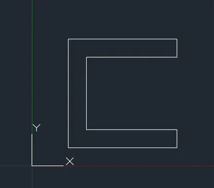
Result : Hence the Diagram P1 is made with Cartesian Co-ordinate system.
2)AIM: To provide the given diagram in P-2 by AutoCAD, and draw the diagram with following Dimensions using Imperial Template and Decimal Unit.
Procedure:
- Command Line in the command box/ From menu bar line can be chosen.
- 1st point as 2,1
- 2nd point as 5,1
- 3rd point as 5,5
- 4th point as 6,5
- 5th point as 6,1
- 6th point as 9,1
- 7th point as 7,8
- 8th point as 4,8
- Close command / 2,1.
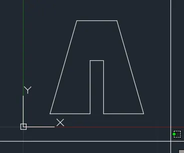
Result : Hence the Diagram P2 is made with Cartesian Co-ordinate system.
3)AIM: To provide the given diagram in P-4 by AutoCAD, and draw the diagram with following Dimensions using Imperial Template and Decimal Unit.
Procedure:
- Command Line in the command box/ From menu bar line can be chosen.
- 1st point as 2,1
- 2nd point as 3,1
- 3rd point as 3,5
- 4th point as 5,3
- 5th point as 7,5
- 6th point as 7,1
- 7th point as 8,1
- 8th point as 8,8
- 9th point as 7,8
- 10th point as 5,5
- 11th point as 3,8
- 12th point as 2,8
- Close command / 2,1.

Result : Hence the Diagram P4 is made with Cartesian Co-ordinate system.
4)AIM: To provide the given diagram in P-5 by AutoCAD, and draw the diagram with following Dimensions using Imperial Template and Decimal Unit.
Procedure:
- Command Line in the command box/ From menu bar line can be chosen.
- 1st point as 2,1
- 2nd point as @ 0,8
- 3rd point as @ 7,0
- 4th point as @ 0,-8
- 5th point as @ -4,0
- 6th point as @ 0,1
- 7th point as @ 3,0
- 8th point as @ 0,6
- 9th point as @ -5,0
- 10th point as @0,-7
- Close command / 2,1.
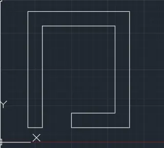
Result : Hence the Diagram P4 is made with Relative Rectangle Co-ordinate system.
5)AIM: To provide the given diagram in P-7 by AutoCAD, and draw the diagram with following Dimensions using Imperial Template and Decimal Unit.
Procedure:
- Command Line in the command box/ From menu bar line can be chosen.
- 1st point as 2,1
- 2nd point as @ 0,6
- 3rd point as @ 8,0
- 4th point as @ 0,-6
- Close Command
Next:
- 5th point as 3,2
- 6th point as @ 0,3
- 7th point as @ 2,0
- 8th point as @ 0,-3
- Close Command
Next:
- 9th point as 6,2
- 10th point as @ 0,3
- 11th point as @ 2,0
- 12th point as @ 0,-3
- Close Command
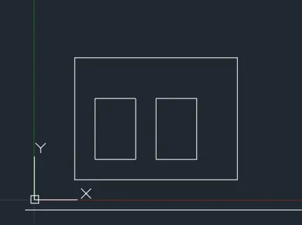
Result : Hence the Diagram P7 is made with Relative Rectangle and Cartesian Co-ordinate system.
6)AIM: To provide the given diagram in P-8 by AutoCAD, and draw the diagram with following Dimensions using Imperial Template and Decimal Unit.
Procedure:
- Command Line in the command box/ From menu bar line can be chosen.
- 1st point as 0,0
- 2nd point as @ 10<0
- 3rd point as @ 2<90
- 4th point as @ 4<180
- 5th point as @ 4<90
- 6th point as @ 3<0
- 7th point as @ 2<90
- 8th point as @ 8<180
- 9th point as @ 2<270
- 10th point as @ 3<0
- 11th point as @ 4<270
- 12th point as @ 4<180
- Close command.
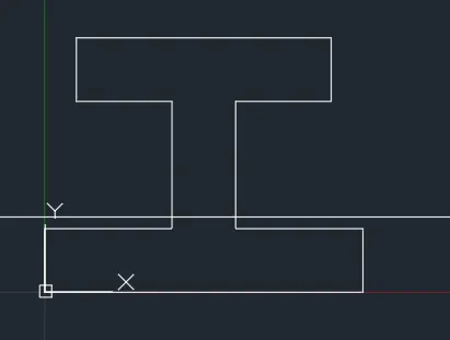
Result : Hence the Diagram P7 is made with Polar Co-ordinate system.
7)AIM: To provide the given diagram in P-9 by AutoCAD, and draw the diagram with following Dimensions using Imperial Template and Decimal Unit.
Procedure:
- Command Line in the command box/ From menu bar line can be chosen.
- 1st point as 1,1
- 2nd point as @ 5<0
- 3rd point as @ 2<90
- 4th point as @ 3<180
- 5th point as @ 1<270
- 6th point as @ 1<180
- 7th point as @ 2<90
- 8th point as @ 3<0
- 9th point as 1,8
- Close command.
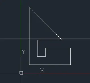
Result : Hence the Diagram P9 is made with Polar and Cartesian Co-ordinate system.
8)AIM: To provide the given diagram in P-10 by AutoCAD, and draw the diagram with following Dimensions using Imperial Template and Decimal Unit.
Procedure:
- Command Line in the command box/ From menu bar line can be chosen.
- 1st point as 1,1
- 2nd point as @ 7<90
- 3rd point as @ 5<90
- 4th point as @ 4<270
- 5th point as @ 3<180
- 6th point as @ 3<270
- CLose command.
Next:
- 7th point as 2,5
- 8th point as @ 2<900
- 9th point as @ 3<0
- 10th point as @ 2<270
- Close command.
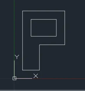
Result : Hence the Diagram P10 is made with Polar and Cartesian Co-ordinate system.
9)AIM: To provide the given Profile wood diagram in by AutoCAD.
Procedure:
- Command Line in the command box/ From menu bar line can be chosen.
- 1st point as 0,0
- 2nd point as @ 10<0
- 3rd point as @ 1<90
- 4th point as @ 2<180
- 5th point as @ 4<90
- 6th point as @ 2<0
- 7th point as @1<90
- 8th point as 5,9
- 9th point as 0,6
- 10th point as @ 2<0
- 11th Point as @5<270
- 12th point as @2<180
- Close command.
Next:
- Command circle in the command box/ From menu bar line can be chosen.
- 1st point as 5,4
- 2nd point radius as 2.
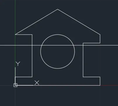
Result : Hence the Diagram is made with Polar and Cartesian Co-ordinate system.
10)AIM: To provide the given Queen Truss diagram in by AutoCAD.
Procedure:
- Command Line in the command box/ From menu bar line can be chosen.
- 1st point as 1,1
- 2nd point as @ 4<90
- 3rd point as @ 5<25
- 4th point as @ 5<315
- 5th point as @ 7<180
- Active ortho, Direct Distance Co-ordinate stytem 4
- Active ortho, Direct Distance Co-ordinate stytem 3.5
- Line command 2,5
- @0,1 Rectangular co-ordinate sysyem
- Close command.
- Line command 7,5
- @0,1 Rectangular co-ordinate sysyem
- Close command.
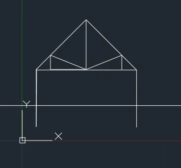
Result : Hence the Diagram is made with Polar, Cartesian, Rectangular and Direct distance Co-ordinate system.
11)AIM: To provide the given Mono Pitch diagram in by AutoCAD.
Procedure:
- Command Line in the command box/ From menu bar line can be chosen.
- 1st point as 1,1
- 2nd point as @ 6<0
- 3rd point as @ 2<90
- Close command
- 4th point as 5,1
- 5th point as @ 0,1.333
- Close command
- 6th point as @ 0,o.667
- Close command.
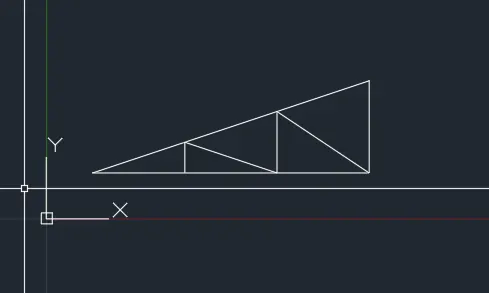
Result : Hence the Diagram is made with Polar, Cartesian, Rectangular and Direct distance Co-ordinate system.