Creating a Floor plan, Footing detail and Isometric view using AutoCad
1) Aim: To construct/draw the C.S of load bearing wall on spread footing using AutoCad.
Procedure:
- Setting the units into meter.
- Cronstructing the structure by the given measurements.
- 1st point as 2,1
- Creating the lower footing according to the measurements of .90 m width and .25 m height.
- Plotting a ceneter line of the symmetric structure.
- With reference to the center line mirroring the whole structrure.
- with the help of the given measurements constructing the steps.
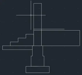
Result: Thus, C.S of load bearing wall on spread footing is constructed using AutoCad.
2)Aim: To construct C.S. of Isolated Footing using AutoCad.
Procedure:
- Setting the units into meter.
- Cronstructing the structure by the given measurements.
- 1st point as 2,1
- 2nd point as 0.50 m
- 3rd point as .15 m as given in structure
- 4th point as @ .38,.25 m
- Then mirrioring the whole structure with reference to the center
- Then taking .04 m from top, taking 1.96 m down and .38 m to left
- Mirrioring the same with reference to the center.
- Drawing the tie bars with offset tool with .20 m as offset point.
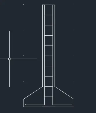
Result: Thus, C.S. of Isolated Footing is constructed using AutoCad.
3) Aim: To construct line diagram of two bedroom building using AutoCad.
Procedure:
- Setting the units into meter.
- Cronstructing the structure by the given measurements.
- 1st point as 2,1
- With reference to 1st point take 3.6 m
- 2nd point as 1.8 m i.e. center
- Drawing staircase by offset of 0.30 m
- 4th point as 4.20 m and last point as 1.8 m
- Mirrioring the whole symmetric structure taking center point as reference.
- Inserting the text accordingly.
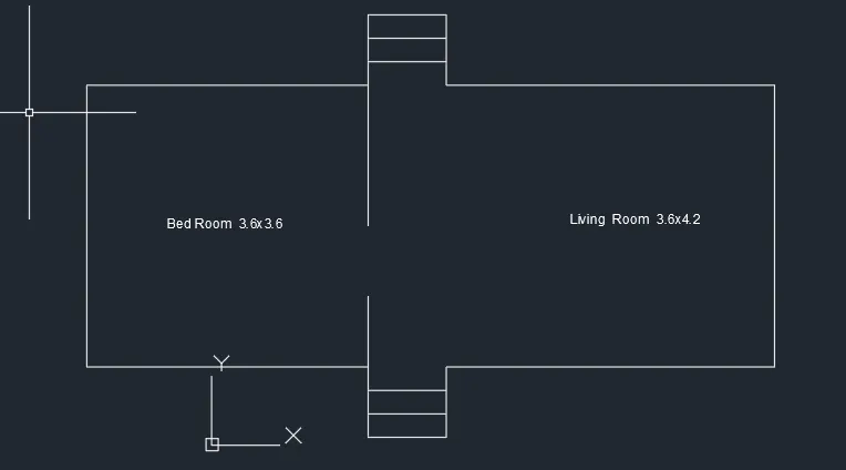
Result: Thus,line diagram of two bedroom building is constructed using AutoCad.
4)Aim: To construct C.S of load bearing wall showing foundation details using AutoCad.
Procedure:
- Setting the units into meter.
- Cronstructing the structure by the given measurements.
- 1st point as 2,1 and switching ortho on.
- 1st point as .90 m
- and height as .45 m
- constructing one side of the the footing with the provided measurements
- Mirroring the whole diagram by taking center as reference.
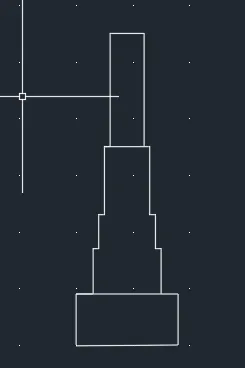
Result: Thus, C.S of load bearing wall showing foundation details is constructed using AutoCad.
5)Aim: To construct Isometric diagram of steps using AutoCad.
Procedure:
- Putting ortho and isometric cursor on.
- Switching to isometric right and top plane.
- Measurement of .15 m as riser and .30 m as tread
- Copying the structure of 5 nos. riser, paste it to a distance of 1 m.
- With ortho on draw and jon the in between lines with help of offset or copy
- Drawing .15m from the top landing and .30m from the bottom landing, joining the line in between with the refrence end points.
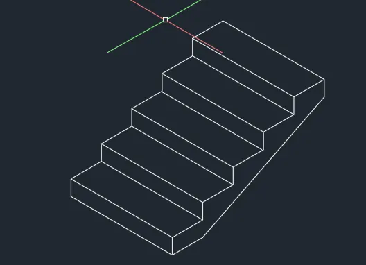
Result: Thus, Isometric diagram of steps is constructed using AutoCad.
6) Aim: To construct Isometric view of gable wall using AutoCad.
Procedure:
- Putting ortho and isometric cursor on.
- Switching to isometric right and top plane.
- Drawing the outer frame of 3m side, 3m bottom and again 3m side
- Drawing the centerline of the frame as 3.25 m as given
- Joining the points to the top to create the gable
- Erasing the un necessary lines
- Drawing a door of height 2.42 m height and 1 m width.
- Taking the width if wall as .30 m and coping the structure and creating a plane at distance of .30 m
- Finally joining the remaining lines.
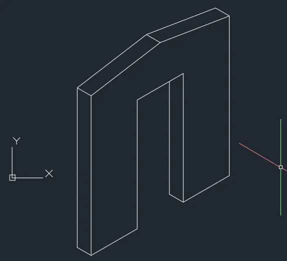
Result: Thus, Isometric view of gable wall is constructed using AutoCad.