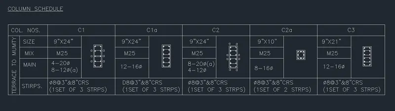
Creation of Column Schedule and Drawing Template using AutoCad
- Create a column schedule as shown in the figure.
Note: Create a column schedule with the help of lines. Also insert text with the help of Dtext command or Single Line text.
Hint: Use font name: romans shx; height:8”, Justify: Left.
Aim: to create a column schedule using AutoCAD software.
Introduction:
Various commands used
- QNEW command
- Unit command
- Line command
- ST command
- Dtext command
- Scale command
- Divide command
- DDPTYPE command
- Circle command
- Hatch command
- Rectangle command
- Explode command
- Mirror command
- Copy command
- Copy command
- ED command
Procedure:
- Open AutoCAD software.
- Type QNEW in command box and press enter.
- Choose imperial as default setting.
- Type UN in command box and press enter.
- Select the architectural as measurement unit with precision of 0’-0”.
- Type L in command box and create the table of size 67’x12’-6” using line tool along with offset and trim tool.
- Type ST in command box and press enter.
- In the text style dialog box select the font name as romans shx, in size type height as 0’-8”, in effects width factor as 1 and oblique angle as 0.
- Select apply and close respectively.
- For creating heading of table, Type Mtext in command box and press enter.
- Select the justify option in command box and click on left option.
- Specify start point of text, specify rotation angle as 0, press enter.
- Click on underline option in ribbon of text editor. Press capsLK and type text as ‘’column schedule”.
- Type Dtext in command box and press enter.
- Select the justify option in command box and click on left option.
- Specify start point of text, specify rotation angle as 90, press enter and type text as ‘’TERRACE TO MUMTY”.
- Select the text and choose MOVE tool and move it to the first column of table.
- Again, type Dtext and press enter.
- Select the justify option in command box and click on left option.
- Specify start point of text, specify rotation angle as 0, press enter and type text as ‘’size”.
- Type CO in command box and select the object as SIZE text.
- Select the base point as center of SIZE text and copy it to all the boxes of table.
- Type ED in command box and press enter.
- Select the text and edit it with respective text content.
- In annotate tab select the multiline text, select the first point, then specify opposite corner point.
- Type MTEXT as 4-20, after which from text editor in symbol drop-down choose the diameter option for diameter symbol press enter and type 8-12 again choose diameter option in symbol drop-down and type (a), the press escape.
- Select the just written multiline text and copy it to required position using copy tool and edit it using the ED command.
- Drawing the cross section of C1
- Type rec in command box, press enter and specify first corner point.
- Click on dimension option in command box, specify length as 9”, width as 24” and press enter.
- Type O in command box and press enter.
- Specify offset distance as 1” and take offset to rectangle in inner side.
- Type EXPLODE in command box; press enter and select the inner rectangle to explode.
- Type DIVIDE in command box, press enter and select the width of rectangle.
- Enter number of segments to divide as 4 and press enter.
- Type DDPTYPE in command box, press enter and change the point style so that it can easily visible.
- For drawing the rebars in column from the ribbon in home tab select the circle tool and in that select tangent, tangent and radius option.
- Select first tangent as top length, second tangent as left side width of inner rectangle and specify radius as 0.5” and press enter.
- Type H in command box and press enter.
- Select the solid hatch pattern and pick internal point as center of circle.
- Type MIR in command box and select object as just drawn circle and press enter.
- Select first mirror point as midpoint of left side width and second mirror point as center of rectangle it will create the rebars.
- Make sure that visibility of center, geometric center, midpoint, endpoint, quadrant, node and tangent is on in object snap setting.
- Type co in command box, press enter and select the left top corner circle along with hatch.
- Press enter and select base point as left quadrant of first circle and copy it in the position of points and press escape.
- Select the points and erase it using erase tool.
- Type MIR in command box, press enter, select the left part of rectangle and press enter.
- Select first mirror point as midpoint of top length and second mirror point as geometric center of the rectangle.
- Type L in command box, press enter and join the quadrants of circle for drawing the stirrups as per position of stirrups.
- Type Fin command box, press enter, click on multiple option followed by radius in command box and specify radius as 0.5” and press enter.
- Fillet the corners of inner rectangles to create the bends.
- For drawing the hook, Type CO in command box, press enter.
- Select any one drawn circle and copy it to outside the rectangle.
- Using line tool draw the vertical lines of 0.5” length from two opposite quadrants of circle.
- Type TR in command box and trim the inner arc of the circle.
- Type Ro in command box, select just drawn hook and press enter.
- Select the base point as center of circle as and specify base point as center of circle.
- Specify rotation angle as 45 and press enter.
- Type MOVE in command box, select the just drawn hook and position it to the required position by coinciding center of hook with the center of circle.
- Again, rotate the hook in angle of rotation 90 in similar way as mentioned above by using the rotation tool and move it to required position using move tool.
- Type SC in command box and press enter.
- Select the object as whole drawing of cross section of column and press enter.
- Select the base point as corner of rectangle as specify scale factor as 2 and press enter.
- From multiline text select the alpha symbol and copy it to required position using the copy tool.
- Drawing the cross section of C1a, C2
- Drawing of cross section of C1a and C2 is similar to that of C1 expect that in this case divide the left width of rectangle in five segments for positioning the rebars in column cross section and join the quadrants of circles according to the positions of stirrups.
- In case of C2, from multiline text select the alpha symbol and copy it to required position using the copy tool.
- Drawing the cross section of C2a
- Type rec in command box, press enter and specify first corner point.
- Click on dimension option in command box, specify length as 9”, width as 10” and press enter.
- Type O in command box and press enter.
- Specify offset distance as 1” and take offset to rectangle in inner side.
- For drawing the rebars in column from the ribbon in home tab select the circle tool and in that select tangent, tangent and radius option.
- Select first tangent as top length, second tangent as left side width of inner rectangle and specify radius as 0.5” and press enter.
- Type H in command box and press enter.
- Select the solid hatch pattern and pick internal point as center of circle.
- Type MIR in command box and select object as just drawn circle and press enter.
- Select first mirror point as midpoint of left side width and second mirror point as center of rectangle it will create the rebars.
- Type co in command box, press enter and select the left top corner circle along with hatch.
- Press enter and select base point as left quadrant of first circle and copy it to the midpoint of left width of inner rectangle with left quadrant coinciding the midpoint.
- Type MIR in command box, press enter, select the left part of rectangle and press enter.
- Select first mirror point as midpoint of top length and second mirror point as geometric center of the rectangle.
- Type L in command box, press enter and join the tangent points of middle circles to draw the stirrups using tangential object snap.
- Type SC in command box and press enter.
- Select the object as whole drawing of cross section of column and press enter.
- Select the base point as corner of rectangle as specify scale factor as 2 and press enter.
- Drawing the cross section of C3.
- Procedure for drawing the cross section of C3 is similar as that of cross section of C1a and C2 expect that in case of C3 column specify width of rectangle as 21”.
Result:
Therefore, column schedule is prepared successfully using AutoCAD software by following the above procedure as shown below.
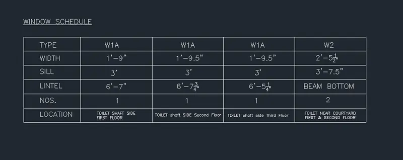
- Create a window schedule as shown in the figures:
Aim: To create the window schedule using AutoCAD software.
Introduction:
Various command used
- QNEW command
- UN command
- ST command
- Line command
- Ortho command
- Dtext command
- MTEXT command
- ED command
- Trim command
- Copy command
Procedure
- Open AutoCAD software.
- Type QNEW in command box and press enter.
- Choose imperial as default setting.
- Type UN in command box and press enter.
- Select the architectural as measurement unit with precision of 0’-0”.
- Type ST in command box and press enter.
- In the text style dialog box select the font name as romans shx, in size type height as 0’-8”, in effects width factor as 1 and oblique angle as 0.
- Type L in command box and press enter.
- Make ortho mode on.
- Draw the horizontal line of length 48’.
- Type O in command box, press enter and take offset of 2’ in downward direction.
- Using the line tool draw the vertical line for drawing the table.
- Type O in command box and press enter.
- Specify offset distance as 8’ and take offset in right direction.
- Again, type O in command box and press enter.
- Specify offset distance 10’, press enter and take 5 offsets in right direction.
- Using the trim tool, create table of 48’x12’.
- For creating heading of table, Type Mtext in command box and press enter.
- Select the justify option in command box and click on left option.
- Specify start point of text, specify rotation angle as 0, press enter.
- Click on underline option in ribbon of text editor. Press capsLK and type text as ‘’column schedule”.
- Type Dtext in command box and press enter.
- Specify first corner.
- Click on justification option in command box and choose middle center option in justification.
- Specify opposite corner and type the text.
- Specify start point of text, specify rotation angle as 0, press enter and type text as ‘’SIZE”.
- Type CO in command box and press enter.
- Select the text and press enter.
- Select the base point of text and copy it to required position.
- Type ED and press enter.
- Click on Mode option followed by clicking of multiple option in command box.
- Select the text and edit the text as per required content.
- Make sure that ortho mode is on to align the text in middle of the table box.
- Type MTEXT in command box, press enter.
- Specify first corner.
- Click on justification option in command box and choose middle center option in justification.
- Specify opposite corner and type the text as 2’-5.
- Type CO in command box and press enter.
- Select the text and press enter.
- Select the base point of text and copy it to required position.
- Type ED and press enter.
- Click on Mode option followed by clicking of multiple option in command box.
- Select the text and edit the text as per required content.
- Type ST in command box and press enter.
- In the size option change the height of font to 5” and click on ok.
- Type MTEXT in command box, press enter.
- Specify first corner.
- Click on justification option in command box and choose middle center option in justification.
- Specify opposite corner and type the text.
- Type CO in command box and press enter.
- Select the text and press enter.
- Select the base point of text and copy it to required position.
- Type ED and press enter.
- Edit the text as per required content.
Result:
Therefore, window schedule is drawn using AutoCAD software by following the above procedure as shown below.
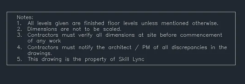
- Create the drawing template as shown in the figure:< Use the Notes as in the figure>
Aim: To create the drawing template using AutoCAD software.
Introduction:
Various commands used
- QNEW command
- UN command
- ST command
- MTEXT command
- REC command
- Line command
- Offset command
- Explode command
- Trim command
- EDTEXT command
- ED command
- Copy command
Procedure:
- Open AutoCAD software.
- Type QNEW in command box and press enter.
- Choose imperial as default setting.
- Type UN in command box and press enter.
- Select the architectural as measurement unit with precision of 0’-0”.
- Type ST in command box and press enter.
- In the text style dialog box select the font name as romans shx, in size type height as 0’-8”, in effects width factor as 1 and oblique angle as 0.
- Select apply and close respectively.
- Type MTEXT in command box, press enter.
- Specify first corner.
- Click on justification option in command box and in that select the left justification.
- Specify opposite corner.
- Type the content text.
- Use the bullets and numbering option from the text editor for numbering the lines in the text wherever required.
- Type rec in command box, press enter.
- Specify first corner as corner of above text and specify opposite corner as second corner.
- The above drawn rectangle acts as column for the text content.
- Type L in command box, press enter.
- Specify first point as top right corner of rectangle and draw the horizontal line of 54’ unit length.
- Type O in command box and press enter.
- Specify offset distance as 2’ and take offset in downward direction.
- Type EXPLODE in command box and press enter.
- Select the rectangle and explode it.
- Type O in command box and press enter.
- Specify offset distance as 15’and press enter.
- Take two offsets in right direction to the vertical line.
- Again, type O in command box and press enter.
- Specify offset distance as 8’ and press enter.
- Take three offset in right direction to the just drawn vertical line.
- Using trim tool trim the extra lines to create the table as per requirement.
- Type Dtext in command box and press enter.
- Specify first point.
- Click on the justification option in command box and click on left option.
- Type the text content.
- Type CO in command box and press enter.
- Select the text and press enter.
- Select the base point of text and copy it to the required position.
- Type ED in command box and press enter
- Click on mode option followed by multiple option in command box.
- Edit the text as per requirement of the text.
Result:
The drawing template is created using AutoCAD software by following above mentioned procedure is as follows.

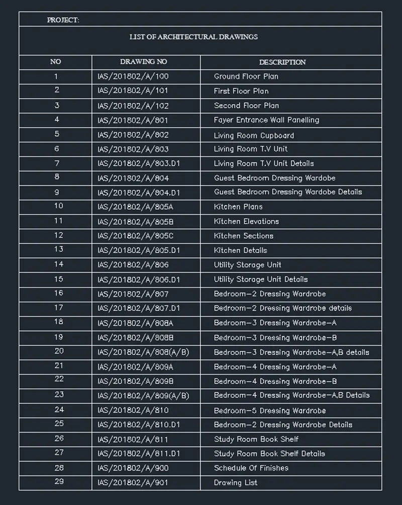
- Create the list of drawing schedule as shown in the figure:
Aim: To create the list of drawing schedule using AutoCAD sofware.
Introduction:
Various commands used
- Line command
- Offset command
- Erase command
- EDTEXT command
- Trim command
- Copy command
- MTEXT command
- ED command
Procedure:
- Open AutoCAD software.
- Type QNEW in command box and press enter.
- Choose imperial as default setting.
- Type UN in command box and press enter.
- Select the architectural as measurement unit with precision of 0’-0”.
- Type ST in command box and press enter.
- In the text style dialog box select the font name as romans shx, in size type height as 0’-8”, in effects width factor as 1 and oblique angle as 0.
- Type L in command box and press enter.
- Make ortho mode on.
- For drawing the table, draw horizontal line of 50’ length.
- Type O in command box and press enter.
- Specify offset distance as 2’ and press enter.
- Take 31 offsets in downward direction to the drawn horizontal line.
- Type E in command box and press enter.
- Select the third horizontal line and erase it.
- Type L in command box.
- Specify first point as first endpoint of horizontal line and draw the vertical line joining the start points of each drawn horizontal line.
- Type O in command box and press enter.
- Specify offset distance 10’ and take offset in right direction.
- Type O in command box, press enter, specify offset distance 15’ and press enter.
- Take offset in right direction to the just drawn vertical line.
- Again, Type O in command box, press enter, specify offset distance 25’ and press enter.
- Take offset in right direction to the just drawn vertical line.
- Type TR in command box, press enter and trim the extra lines.
- Type EDTEXT in command box and press enter.
- Click on justify option in command boa and click on left option.
- Specify start point of text, type rotation angle of text as 0 and press enter.
- Type the text content in their respective position.
- Type MTEXT in command box and press ok.
- Specify first starting point and opposite corner.
- Type the text as “PROJECT”.
- Type ED in command box and press enter.
- Select the text and change the font style to romantic to make the tittles.
- Type CO in command box ,press enter, select the text ,and press enter.
- Select the base point and copy it to required position.
- Type ED in command box and press enter.
- Select the text and edit it as per required content.
Result:
Therefore, using the AutoCAD software the list of drawing schedule is created by following the above mentioned procedure as shown below.
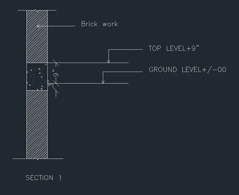
- Create the Beam detail as shown in the figure and provide text wherever given.
Aim: to create the Beam details using AutoCAD software.
Introduction:
Various commands used
- QNEW command
- UN command
- Line command
- Trim command
- Offset command
- Dimlinear command
- Hatch command
- DTEXT command.
Procedure:
- Open AutoCAD software.
- Type QNEW in command box and press enter.
- Select default setting as imperial and select ok.
- Type UN in command box and press enter.
- Select the unit as architectural with precision of 0’-0” and select ok.
- Type L in command box and press enter.
- Specify first corner and draw the vertical line and press escape.
- Type O in command box and press enter.
- Specify offset distance as 9” and press enter.
- Select the line and take offset in the right direction.
- Again choose line tool and draw the horizontal line intersecting to the vertical lines.
- Type O in command box and press enter.
- Specify offset distance 9” and press enter.
- Select the horizontal line and take offset in downward direction.
- Again, type O in command box and press enter.
- Specify offset distance as 3” and press enter.
- Select the bottom horizontal line and take offset in downward direction to drawn horizontal line.
- Type TR in command box and trim the extra lines wherever required.
- Type H in command box and click on setting option in the command box.
- Select the pattern as AR-CON and select the scale 0.75 and click on ok.
- Pick the internal point as cross section of beam in wall cross section and press enter.
- Again, Type H in command box and click on setting option in the command box.
- Select the pattern as ANSI32 and select the scale 2 and click on ok.
- Pick the internal point as cross section of wall.
- Choose the dimension tool and give the dimensions.
- Type DTEXT in command box and press enter.
- Select the start point, specify the text height as 3” and press enter.
- Specify rotation angle as 0 and press enter.
- Type the text content wherever required by moving the cursor with the help of mouse.
- Using line tool draw the arrows for text.
Result:
Therefore, by using the AutoCAD software the beam detail is created by following the above mentioned procedure as shown below.