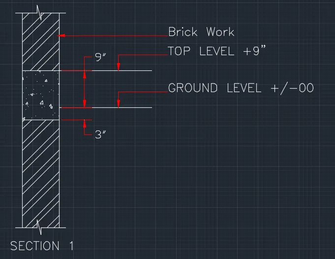
Creation of Column Schedule and Drawing Template using AutoCad
Q1
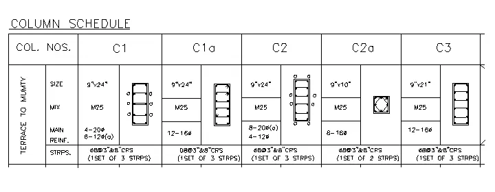
AIM : To create a column schedule as given by using AutoCAD
PROCEDURE
STEP 1 :
Type unit or UN in the command box and press enter
Set type of unit as engineering and precision as 0’0”
In Insertion scale set unit as inches
STEP 2 :
Type line or L in the command box and press enter
Using line command draw the table

STEP 3 :
Type TEXT in the command box and press enter
By changing text style, text height as per the given drawing
STEP 5 :
Type line or L in the command box and press enter
Using line command draw the Column drawing as given
RESULT
The given figure is drawn using text tool, line tool and circle tool
Q2
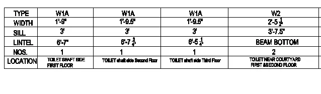
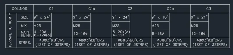
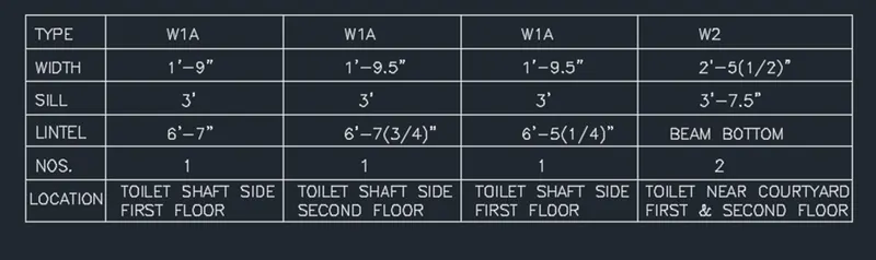
AIM : To create a window schedule as given by using AutoCAD
PROCEDURE
STEP 1 :
Type unit or UN in the command box and press enter
Set type of unit as engineering and precision as 0’0”
In Insertion scale set unit as inches
STEP 2 :
Type line or L in the command box and press enter
Using line command draw the table

STEP 3 :
Type TEXT in the command box and press enter
By changing text style, text height as per the given drawing
RESULT
The given figure is drawn using text tool, line tool
Q3
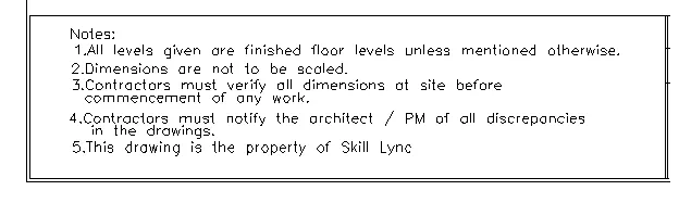

AIM : To create a Drawing template as given by using AutoCAD
PROCEDURE
STEP 1 :
Type unit or UN in the command box and press enter
Set type of unit as engineering and precision as 0’0”
In Insertion scale set unit as inches
STEP 2 :
Type line or L in the command box and press enter
Using line command draw the table
STEP 3 :
Type TEXT in the command box and press enter
By changing text style, text height as per the given drawing
RESULT
The given figure is drawn using text tool, line tool


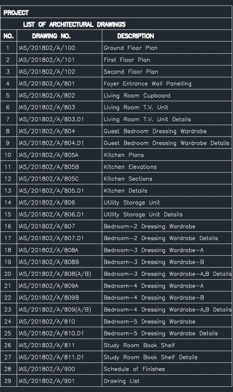
Q4
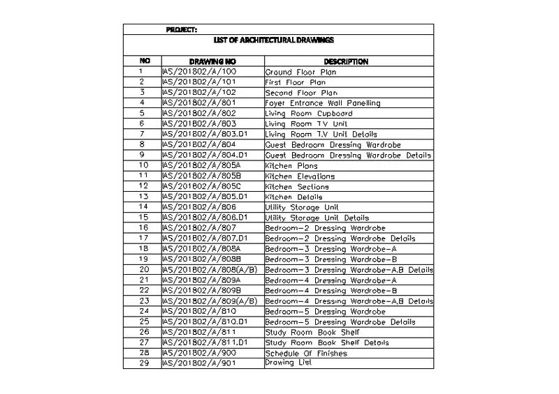
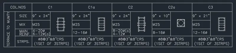
AIM : To create a Drawing template as given by using AutoCAD
PROCEDURE
STEP 1 :
Type unit or UN in the command box and press enter
Set type of unit as engineering and precision as 0’0”
In Insertion scale set unit as inches
STEP 2 :
Type line or L in the command box and press enter
Using line command draw the table
STEP 3 :
Type TEXT in the command box and press enter
By changing text style, text height as per the given drawing
RESULT
The given figure is drawn using text tool and table tool
Q5
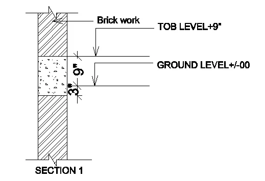
AIM : To create a Beam detail as given by using AutoCAD
PROCEDURE
STEP 1 :
Type unit or UN in the command box and press enter
Set type of unit as engineering and precision as 0’-0”
In Insertion scale set unit as inches
STEP 2 :
Type dimension style manager or D in the command box and press enter
Modify primary units as engineering and precision as 0’-0”
STEP 3 :
Type line or L in the command box and press enter
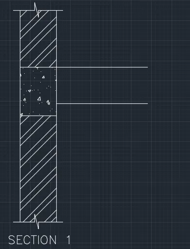
Using line command draw the wall and beam
Type hatch or HA in the command box and press enter
Hatch the wall internal part
STEP 4 :
Type DIM in the command box and press enter
Add required dimensions to drawing
Type quick leader or QL in the command box and press enter
Select the object draw arrow and name the object
Type TEXT in the command box and press enter
Add room names
RESULT
The figure given is drawn using line tool, hatch tool, dimension tool and text tool.