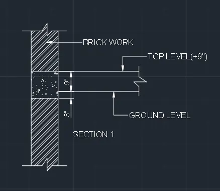
Creation of Column Schedule and Drawing Template using AutoCad
Q1
AIM:- To create a column schedule
step 1:- to draw the cross-section of the column
- take a line command
- specify the first point
- specify the next point and construct the crosssection of the column
- specify the cover to the column crosssection
- specify the number of main reinforcement bars
- specify the stirrups to the main reinforcement
- connect the hooks to the stirrups
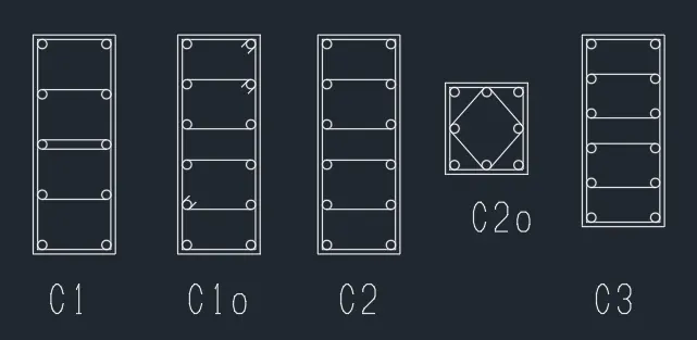
step 2:-
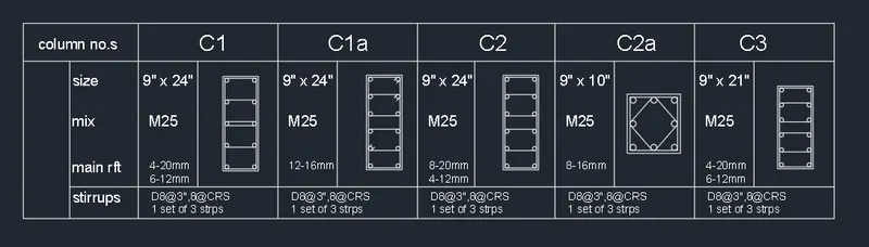
- create a table by taking the line command
- copy the cross-section of the column in the table
- type the text as mentioned
- specify the size of the column'
- specify the area of main reinforcement
- mention the specifications of the stirrups
- mention the number of the column
- type the text as required
Q2
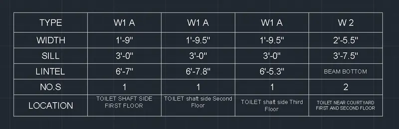
AIM:- To create a table and type the text as given
- take a table command
- then specify the number of columns and number of rows of the table
- then specify the point
- table is displayed
- now adjust the width of the column and the row height from the table properties
- then select one cell of the table
- type the text as given
- change the alignment of the text from the table properties
- format of the text can be changed by the table style command
- if you want to add a number of rows and number of columns can be added through table edit command
Q3
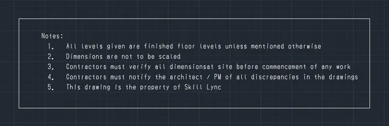
AIM:- to type the text as given in the question
- take Mtext command
- specify the point and drag for the text space
- type the information as given
- select the format as you like
- and take a rectangle command
- specify the first point and next point
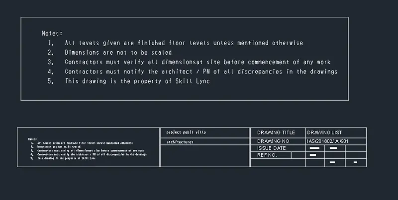
- then copy the text
- and change either the text height or the scale of the text
- then by taking a line command
- create other slots as given and type the text as mentioned
Q4
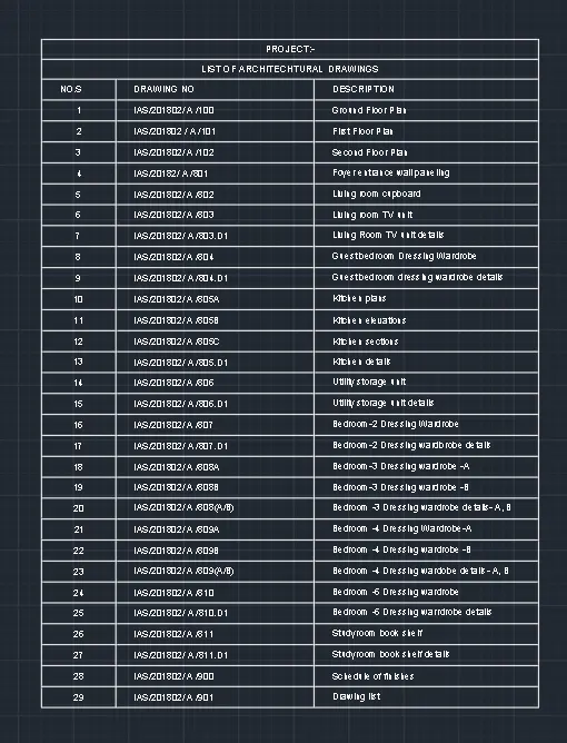
AIM:- To create a table and list the number of drawings of the project as given
- first, create the table with 31 rows and 3 columns
- modify the table properties
- select the cell type as the title for the first two rows
- select the cell type as data for the remaining rows
- adjust the width of the column from the table properties
- select the text alignment as middle left in the table style
- now type the text as given in the question
Q5
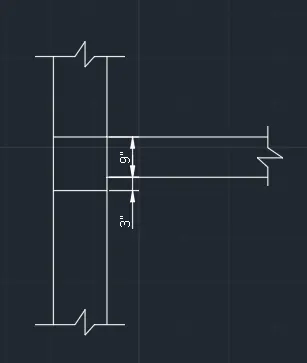
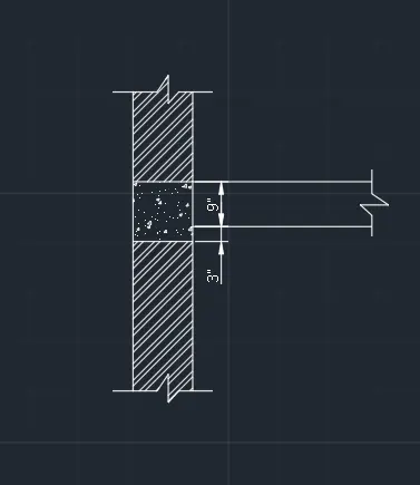
AIM:- to draw the cross-section of the beam and hatch them representing the material and add relevant text.
step 1:- to draw a line diagram of the beam
- take a line command
- specify the first point
- specify the next point as 5'
- then take an offset command and specify the offset distance as 1'
- then at the midpoint of this line draw a horizontal line
- take an offset of 3"
- again take an offset at a distance of 9"
- extend these horizontal lines up to some distance
- add the continuation symbol at the ends of the lines
step 2:- hatching the diagram
- take a hatch command
- select the pattern
- and click the internal point of the object or add pick points of the object
- then click ok and enter
step 3:- addition of text to the diagram
- take a QL command
- specify the first point
- specify the next point
- Click enter
- type in the text
- Click enter