Creation of Column Schedule and Drawing Template using AutoCad
1.
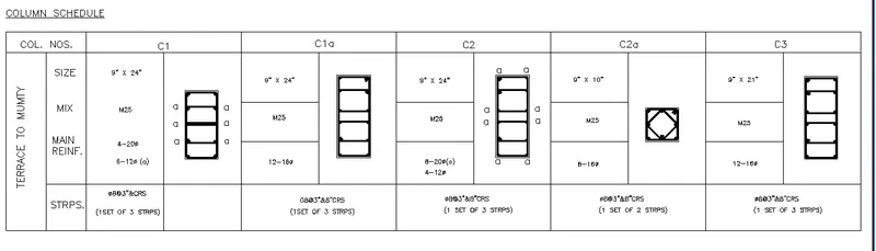
AIM: To create a column schedule with the help of lines.
PROCEDURE:
1. Go to the annotation tab select the the dropdown for the standard and click on manage styles option
2. In the text style dialogue box change the font name as "romans.shx" and give the text height as 8 inches click on the set current option and close the dialogue box.
3. Click on the single line text option from the annotation panel of the Ribbon tab now keeping the ORTHO mode on click on any point and and stretch horizontally ,press enter.
4.Now type the text as"COLUMN SCHEDULE" . Press esc and now click on the line tool from the draw panel of the Ribbon tab and underline the column schedule text keeping the ortho mode on
5. Now draw a vertical line of height 19 feet 10 inch and horizontal line of 8 feet.Enclose the geometry to form the rectangle.
6.Select the offset tool and offset the horizontal line of eight feet to a distance 2 feet 1 inch
7.Dresses ke panno select the line tool again and draw a vertical line from the midpoint of the rectangle.
8.Trim the upper half to get a smaller rectangle.
9.Now click on the single line text option again and give the cursor inside the First row and write the text column numbers.
10. Again draw a single line text entry set vertically and give the text" terrace to mumty " given the text angle of 90°. Similarly give the text size makes and main reinforcement and stirrup. Press esc.
11. Right click and select the entire rectangle and type control C to copy the geometry.
12. Now Press control and specify the base point and paste it further.
13.Again using the single line text option write down the text
14.For the text in the last row of the column C1 press "shift %%c" to get the diameter symbol
15. For the drawing of the section: Draw a rectangle of 6'-10" By 3'-4"
16. Offset the rectangle to a distance of 2 inches in the interior.
17. Use the fillet tool in the modified panel of the Ribbon tab and fill at the corner vertex
18. Use the fillet tool in the modify panel of the Ribbon tab and fillet all the 4 corner vertex of the inner rectangular.
19. Draw a circle of 1.3 inches radius tangential to all four filleted vertex of the inner rectangle
Press escape.Similarly do it for the stirrup in the column C1 C2 C2 a and C3
20. For the further columns copy the previous columns and paste by selecting the base point
Press escape.
RESULT:
2.
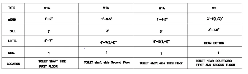
AIM: To create a window schedule as per shown in the given question.
PROCEDURE:
1. Select the line tool from the draw panel of the Ribbon tab and specify at any point and draw a horizontal line of 8'
2. Continue to draw the line of height 23 feet 5.3 inch. Press escape
3.select the Offset tool from the modify panel of the Ribbon tab.
4.Offset the horizontal line of eight feet to a distance of 3 feet 5.3 inch thus by drawing Five horizontal lines.
5.Now from the end point of the first column,draw a horizontal line of length 19 feet 3.5 inches and keeping the polar tracker on container to draw its height joining the priviously Drawn height.
6. Now offset in the same manner.
7. Right click and select the second column and click on copy.
8.Now Press control V to paste the the column by specifying the base point.
9.Paste it thrice to get the entire table.
10.Select the single line text option from the annotation panel of the the Ribbon tab.
11.Now in the first column First row type "TYPE"
12.Right click and go to properties and give the lineweight as 0.3 mm and the height of the text as 8 inches.
13. Similarly write the the text of of all the rows using a single line text option.
14.Now for the the second column write the text w1a.
15.Select the text copy and paste it in the next two columns.
16.Write the other texts using the single line Text option and fill the table.Press escape
RESULT:
3.
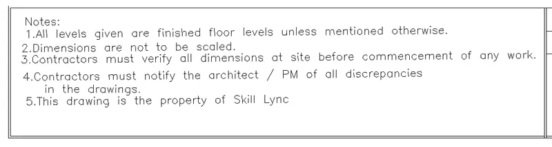
AIM: To create the drawing template as shown in the question (using the Notes as in the figure)
PROCEDURE:
1.Select the line to from the draw panel of the Ribbon tab and specify at any point and draw a horizontal line of 46 feet 7.1 inches
2.Offset that horizontal line to distance of 11 feet 1.8 inches
3.Now select the line tool and join the line to form a rectangle.
4.Select the option tool from the modify panel of the Ribbon tab and offset the vertical line to a distance of 2 inches outwards.
5.now, offset the horizontal line to 2inches
6.Right click and select the entire geometry and copy.
7.Now paste by pressing control v and specify the base point and paste it.
8.Again paste it so that there are three rectangle formed
9.Now shorten the length of the last column to 40 feet 9.8 inches
10.Now draw a vertical line touching the height of the last column and upset it to a distance of 12 feet 3.3 inch twice to get 4 sub columns.
11. Press escape
12. Now select the single line text option from the annotation panel of the Ribbon tab.
13.Inside the first columns specified at the top and right the text as "NOTES"
14.Now write the other context using the same font style giving the height of the text as 8 inches
15.Similarly write down the context of the second column and for the the third column from the data given in the question.Press escape.
RESULT:
4.
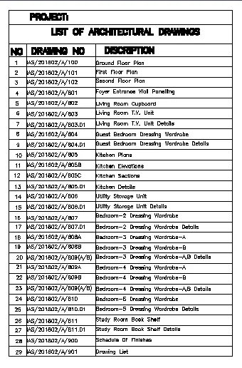
AIM: To create the list of drawing schedule as shown in the question.
PROCEDURE:
1.Select the line tool from the draw panel of the Ribbon tab and draw a horizontal line of 43 feet 4.4 inch. Continue to draw and draw a a height of 7 feet. Press esc and select the offset tool from the modify pannel of the Ribbon tab.
2.offset the horizontal distance to a distance of to 2 feet 9.6 inches and press escape
3. Now from the end point of the rectangle drawn select the line tool and draw a line of height 60 Feet enclose the geometry
4. Now offset the lowermost horizontal line to offset distance of 2 feet 5.7 inches.
5.Again using the same offset tool offset the last drawn line to a distance of 2 feet and keep on offsetting
6.Select the single line text option from the annotation panel of the the Ribbon tab
7.Specify the First row and write down the text "project"
8.Right click and select the text and go to properties and give the height of the text as 1 feet 1 inch and the lineweight to be 0.3 mm
9.Press escape and again click on the single line text and draw the single line text line in the second row and write the text" list of architectural drawing"
10. Press esc and select the offset tool and offset the vertical line to a distance of 3 ft 6.4 inch to form the no. column.
11.Next to the "drawing number" column, offset the drawn vertical line to a distance of 13 feet 4.5 inches and again offset the last drawn line to a distance of 26 feet 5.5 inch
12. Press escape
13.Type "match properties"in the command box and select the source object as the "project" Text in the first row
14.Press enter and now click the text "list of architectural drawings ,number, drawing number and description" text to transfer the properties to these texts.Press escape
15.Now select the single line text from the annotation panel of the Ribbon tab and write down the rest other context in the "NO" "drawing number" and "description" column,this time, giving the text height as 8 inches and line weight as default.Press escape.
RESULT:
5.
AIM: To create the Beam detail as given in the question and providing texts.
PROCEDURE:
1.Select the line tool from the draw panel of the Ribbon tap and specify the cursor anywhere and draw horizontal line of 1 feet 10 inches
2.Continue to draw the line in vertical direction and give the height of 5 feet 11.5 inches
3.Select the offset tool and offset the vertical line to a distance of 1 feet 10 inches and offset the horizontal line to a distance 5 feet 11.5 inches,thus this geometry forms a rectangle.
4.Now off set the bottom horizontal line to a distance of 3 feet 9 inches
5. Press escape and select the extend tool in the drop-down option of trim tool in the modify panel of the Ribbon tab
6. Let the vertical line so that it will be extended thus closing the geometry.press esc
7.Right-click and select the upper rectangle and click on mirror tool
8. Now specify the base point of the lower rectangle and place the mirror image of the rectangle
9. on the object snap settings and switch on the nearest option.
10. Now keeping the earth or mode on from any point on the upper horizontal line draw a small vertical height of random measurement
11. Now switch off the ortho mode and draw a slant line
12.Now again switch on the ortho mode and draw 90 degree perpendicular line to the horizontal line
13.Press esc and select the trim option and trim the vertical line crossing the slant line to get the section
14.Similarly do it for the lower end horizontal Line
15. Select the hatch tool from the Drop panel of the Ribbon tab
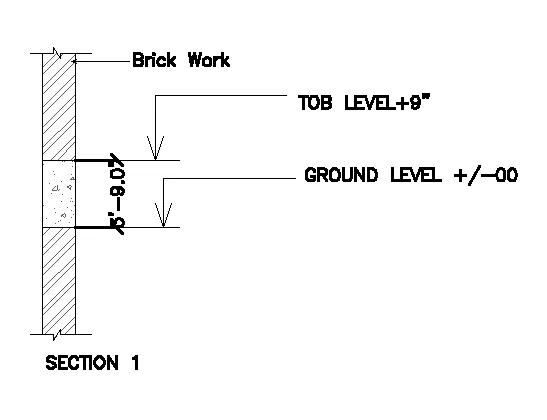
16.Give the ANSI32 hash line for the brick work.Press esc and now select the the AR-CONC hatch and give the concrete has to the middle rectangle
17. Press escape. Select the single line text option and give the namings keeping the lineweight as 0.3 mm and the text height as 8 inches
18.Click on the dimension tool and give the dimensions are shown in the figure given in the question. Press escape.
RESULT: