Creating a Floor plan, Footing detail and Isometric view using AutoCad
C1:
AIM: To draw CS OF LOAD BEARING WALL OVER SPREAD FOOTING :
step1: Set the units to decimal.
step2: Keep the author mode on.
step3: start from any point giving the dimension 0.9 towards positive x axis.
step4: using the direct method,Place the cursor in the positive y axis direction getting the length 0.25.
step5: Keep the midpoint mode in theThe snapSetting.
step6: Draw the centre line.
step7: Offset the line of height 0.4 from the centre line to the distance of 0.25 in the left and right.
step8: Similarly offset for rest of the points to get 0.4 footing.
step9: Draw a horizontal line of 0.3 width at a height of 0.6 and offset the same horizontal distance upwards taking the width of 0.05
step10: Using direct method draw a line 1.15 that extends from a distance of 0.15 from the base of the footing of width 0.3
step11: Accordingly draw the height of 0.15 and horizontal weight of 0.3 followed by 0.15 against 0.3 so on.
step12: Give the dimensions.
C2:
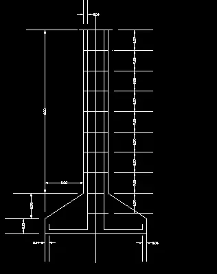
AIM: To draw CS ISOLATED FOOTING:
step1: Take any point specify the distances as 1 unit. Press escape.
step2: Draw Centre line.Press escape
step3: From the endpoint of the 1 unit line draw vertical line of height 0.15 unit.
step4: Draw another vertical line of 0.25 unit. Press escape.
step5: From the height of the last vertical line drawn take a distance of 0.16 from the central line on both the sides.
step6: Now join the line from and height of 0.15 unit to the the last point drawn.
step7: Now use the trim option to cut the the unnecessary height of 0.25 unit. This way a slant line is obtained, same is done on the left end to obtain the slant line.
step8: Draw vertical line ofOf height 1.6 unit from the endpoint of the slanting line.Press escape
step9: offset the lines at a distance of 0.2 unit till the height of 1.6 unit. Press escape.
step10: give the necessary dimensions.
C3:
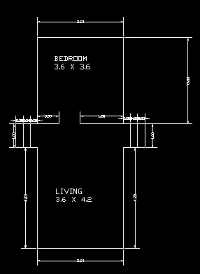
AIM: To draw LINE DIAGRAM OF A TWO BEDROOM BUILDING:
Step1: Type the line command to get a line
Step2: specify any point and draw of horizontal linewhat positive X direction of 3.6 unit.
Step3: Point the cursorIn the negative Y direction and draw the line of 3.6 unit using the direct method.
Step4: Now again placing the cursors in the positive X direction draw a line of 0.9 units.
Step5: Now place the cursor down words and draw a line of 1 unit.
Step6: Place the cursor in negative X directionAnd draw a line of 0.9 units. Press escape.
Step7: offset the line of one unit to a distance of 0.3 and 0.6 on left side
Step8: Press escape.
Step9: from the endpoint of the last line drawn, draw a vertical line of 4.2 units placing the cursor downwards.
Step10: Continue to draw using the direct method placing the cursor in the left direction taking 3.6 units.
Step11: place the cursor in upward direction drawing a line of 4.2 units
Step12: following the same procedure and offsetting the lines.
Step13: Now from the end point of the last drawn line draw vertical line placing the cursor in upward direction taking 3.6 units.
Step14: Press escape
Step15: Go to the text tool in the ribbon
Step16: Drag the text in the middle and give the namings according.
Step17: Giving the necessary dimensions.
C4:
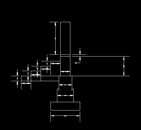
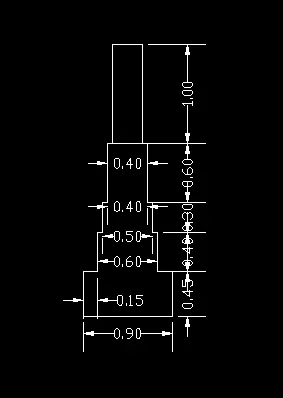
AIM: To draw CS OF LOAD BEARING WALL SHOWING FOUNDATION DETAILS :
Step1: Type the line command to get a line.
Step2: Specify at any point give the horizontal line of 0.9 units.
Step3:from the endpoint of the last drawn line drawn,draw vertical line of 0.45 units placing the cursor in positive y axis direction.
Step4: Complete the box keeping the polar tracker on
Step5: Draw a Centre line.
Step6: now from the midpoint of the longer length that is of the horizontal line of 0.9 unit, draw a vertical line of 0.4 aligning with the centre line.
Step7: Now offset that line Taking the offset distance as 0.25 on both the sides.
Step8: Delete the line that was drawn on the centre line and press escape
Step9: Enclose the line to form a rectangle
Step10: Now from the Midpoint of the base of the upper rectangle draw vertical line aligning with the centre line of height 0.3 units.
Step11:Again off that theVertical line by taking offset distance of 0.2 units in both the left and right side
Step12: Enclosed upper rectangle and delete the vertical middle line. Press escape.
Step13: Now again draw a vertical line align with the centre line of height 1 unitAnd off set it to a distance of0.15
Step14: Enclose the rectangle.
Step15: Now delete the centre line.
Step16: Give the necessary dimensions.
C5:
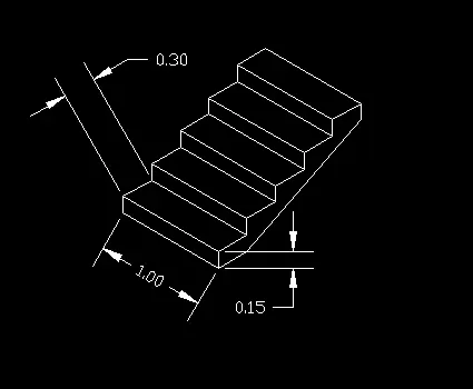
AIM: To draw ISOMETRIC VIEW OF STEPS:
Step1: Go to the snap setting
Step2: switch off the snap on and grid on mode and change the snap type from rectangular snap to isometric snap. Press ok and shut the dialogue box of drafting setting.
Step3: Switch off the ortho mode.
Step4: Now Toggling between isoplane left, isoplane top and isoplane right accordingly while drawing the isometric drawing
Step5: F5 key can also be used to toggle between the isoplanes.
Step6: Specify at any point and draw online of unit 1.
Step7: Now draw the vertical line of unit 0.15.
Step8: Keep the polar tracking mode on.
Step9: change the ISO plane and draw width of the step of unit 0.3
Step10: According to toggle between the ISO planes and draw the remaining drawing placing the cursor in the desired direction of drawing.
Step11: Give the necessary dimensions using the aligned dimension setting option.
C6:
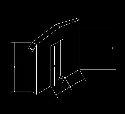
AIM: To draw ISOMETRIC VIEW OF GABLE WALL:
Step1: Go to the snap setting
Step2: switch off the snap on and grid on mode and change the snap type from rectangular snap to isometric snap. Press ok and shut the dialogue box of drafting setting.
Step3: Switch off the ortho mode.
Step4: Now Toggling between isoplane left, isoplane top and isoplane right accordingly while drawing the isometric drawing
Step5: F5 key can also be used to toggle between the isoplanes.
Step6: Specify any point and draw a line of 1 unit.
from 9.2 draw a height of unit 2.42 then continue on to take a horizontal direction of 1 unit again.
Step7: Placing the cursor in the downward direction come back to a distance of 2.4 to unit and draw and then placing the cursor in the positive X direction draw a line of 1 unit.
Step8: From the endpoint of the last drawn lineDraw the height of isometric view of 3 units
Step9: Press escape
Step10: Draw the width of 0.3 unit
Step11: Toggling between the ISO planes extend the width of 0.3 units to a height of3.25 from the base. Join the line to get a slope.Press escape
Step12: offset the vertical height of 2.4 to a distance of 0.3 in the inner direction
Step13: Trim the unnecessary lines
Step14: Give the necessary dimensions.