Creation of Column Schedule and Drawing Template using AutoCad
q1)
Aim:
To create a column schedule, and to draw the column showing reinforcement of the columns in detail.
Introduction:
-The column schedule is a schedule which the details of column will be collected in the construction for design purpose. The column
scheduling is very important thing in column detailing.
-Structural columns are identified in a column schedule by intersecting grid lines and by their top and bottom constraints and offsets. They are placed into the column schedules according to these identifications.
Commands used:
-Limits command
-Single Text command
-Line command
-Dimlinear command
-Trim command
-Mtext command
-Circle command
-object snap command
-DONUT command
-Divide command
-Offset command
-Units command
-Dimstyle command
-Extend command
-Mirror command
Procedure:
Step:-1
Column-1
-First off all we have to open the autocad and set the limits and units.
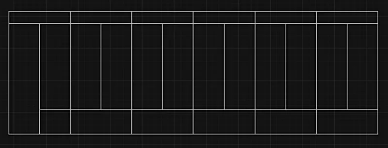
-First we have to draw the table using the line command as shown in below table.
.
-Next we need to enter the details of columns with Single text and Mtext command.
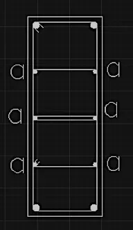
-Then again we draw the column with given details as shown in below figure.
-First we draw the line with the length of 9" horizontally.
-Next we draw the 24" line vertically, then again draw the line with the length of 9".
-Finally we join the first line and last line.
-Then after we do offset of 0.6", and do the offset to inside of rectangle we drawn previously.
-Next draw a circle beside of the previous figure, we take the circle diameter as 20mm
-And take another circle as diameter 12mm.-Now use the divide command and give the 4 segments inside the rectangle.
-Now place the circle in the every segment
-After putting the circles on one side, we use the mirror command.
-Mirror the one side fixed circles to other side.
-And put the 3 stirrups in the column where they are required to put in certain position.
-And Bend the corner of stirrups to the 45 degrees.-And we denote the 12mm bars as "a", as shown in below figure.
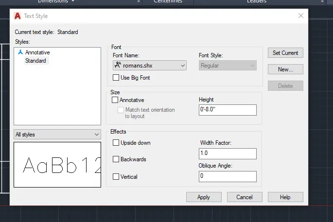
-Type "dimstyle" in the command prompt and press enter.
-From the ribbon tab, select "Annotate". Under text, select "manage text styles". Specify the text height as 8" and font as "roman.shx" .
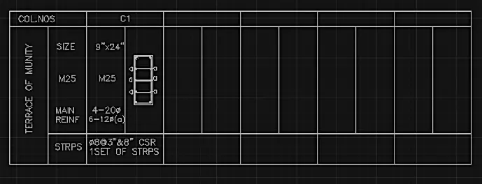
-Next we have to the this overall column data in the table which we have draw first, as shown in below table.
Step 2:
Column-1a
-Here we need to enter the details of columns with Single text and Mtext command.
-Then again we draw the column with given details as shown in below figure.
-First we draw the line with the length of 9" horizontally.
-Next we draw the 24" line vertically, then again draw the line with the length of 9".
-Finally we join the first line and last line.
-Then after we do offset of 0.6", and do the offset to inside of rectangle we drawn previously.
-Next draw a circle beside of the previous figure, we take the circle diameter as 16mm
-Now use the divide command and give the 5 segments inside the rectangle.
-Now place the circle in the every segment.
-After putting the circles on one side, we use the mirror command.
-Mirror the one side fixed circles to other side.
-And put the 3 stimups in the column where they are required to put in certain position.
-And Bend the comer of stimups to the 45 degrees, as shown in below figure
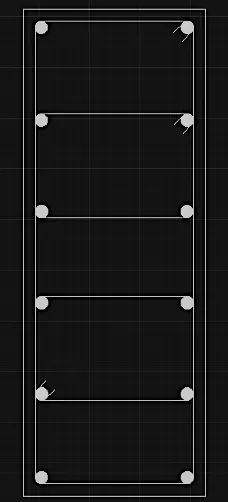
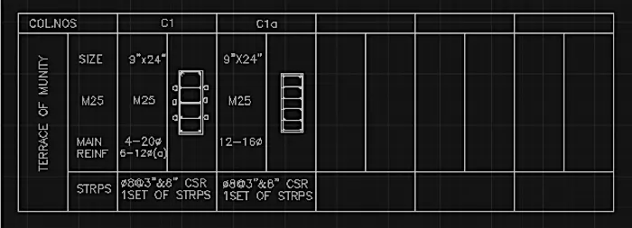
-Next we have to the this overall column data in the table which we have draw first.
-And the details entered in the table as shown in the below table.
Column-2
-Here we need to enter the details of columns with Single text and Mtext command.
-Then again we draw the column with given details as shown in below figure.
-First we draw the line with the length of 9" horizontally.
-Next we draw the 24" line vertically, then again draw the line with the length of 9.
-Finally we join the first line and last line
-Then after we do offset of 0.6", and do the offset to inside of rectangle we drawn previously.
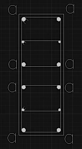
-Next draw a circle beside of the previous figure , we take the circle diameter as 20mm for 8 bars.
-And take another circle as diameter 12mm for 4 bars.
-Now use the divide command and give the 5 segments inside the rectangle.
-Now place the circle in the every segment.
-After putting the circles on one side, we use the mirror command
-Mirror the one side fixed circles to other side.
-And put the 3 stirups in the column where they are required to put in certain position.
-And Bend the comer of stirrups to the 45 degrees, as shown in below figure.
-And we denote the 20mm bars as “a as shown in below figure.
-Here we need to enter the details of columns with Single text and Mtext command.
-Then again we draw the column with given details as shown in below figure.
-First we draw the line with the length of 9" horizontally.
-Next we draw the 10” line vertically then again draw the line with the length of 9°
-Finally we join the first line and last line.
-Then after we do offset of 0.6", and do the offset to inside of rectangle we drawn previously
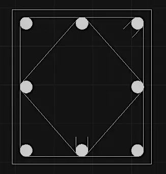
-Next draw a circle beside of the previous figure , we take the circle diameter as 16mm for 8 bars.
-Now use the divide command and give the 2 segments inside the rectangle.
-Now place the circle in the every segment.
-After putting the circles on one side, we use the mirror command,
-And we have to put the 1émm bars in middle also.
-And put the 2 stirrups in the column where they are required
-And Bend the corner of stirrups to the 45 degrees, as shown in below figure.
Step 3
Column-3
-Now we need to enter the details of columns with Single text and Mtext command.
-Then again we draw the column with given details as shown in below figure.
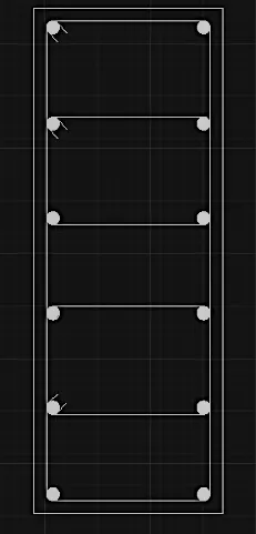
-First we draw the line with the length of 9" horizontally.
-Next we draw the 24" line vertically, then again draw the line with the length of 9°.
-Finally we join the first line and last line.
-Then after we do offset of 0.6", and do the offset to inside of rectangle we drawn previously.
-Next draw a circle beside of the previous figure , we take the circle diameter as 16mm
-Now use the divide command and give the 5 segments inside the rectangle.
-Now place the circle in the every segment.
-After putting the circles on one side, we use the mirror command.
-Mirror the one side fixed circles to other side.
-And put the 3 stirrups in the column where they are required to put in certain position.
-And Bend the corner of stirrups to the 45 degrees, as shown in below figure.
-Next we have to the this overall column data in the table which we have draw first.
-And the details entered in the table as shown in the below table.
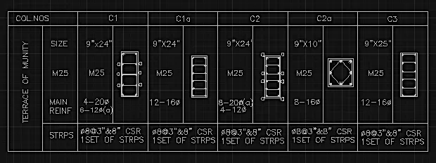
OUTPUT:
*Column schedule is created as shown in the figure.
q2)
AIM:
-To Create a window schedule as shown in the figures and the details mentioned in it
INTRODUCTION:
-The window schedule is a schedule which the details of the windows in construction can be collected in the table form for the construction purposes.
Commands used:
-Limits command
-Single Text command
-Line command
-Dimlinear command
-Trim command
-Object snap command
-Offset command
-Units command
-Dimstyle command
-Extend command
PROCEDURE:
-First off all we have to open the autocad and set the limits and units.
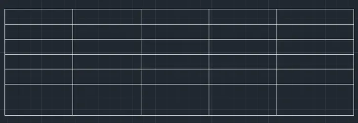
-Next we have to draw the table using the line command as shown in below table.
-We draw the 5 columns and the 6 rows for the window scheduling.
Step:-2
-Next we enter the details of the various windows in the window schedule.
-And we draw the window schedule and enter the details of them in the tabular form.
-The window schedule with various window details was shown in below table.
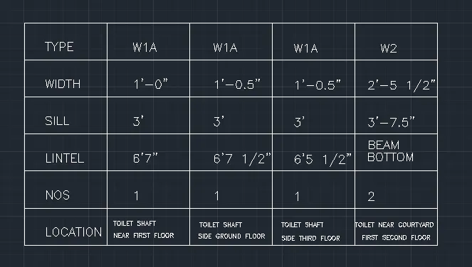
OUTPUT:
*Window schedule is created as shown in the figures
q3)
AIM:
-To Create the drawing template as shown in the figure
INTRODUCTION:
-Drawing template files are drawings that store styles, settings, layers, and layouts in a drawing including title blocks.
-When you create a new drawing based on a drawing template, the new drawing gets a copy of the styles in the template, but it is a one-time copy.
Commands used:
-Limits command
-Single Text command
-Line command
-Dimlinear command
-Trim command
-Object snap command
-Offset command
-Units command
-Dimstyle command
-Extend command
Procedure:
Step-1
-First off all we have to open the autocad and set the limits and units.
-Next we have to draw the table using the line command as shown in below table.
-We draw this table for the entering the details of the entire project before submitting to the client.
-After entering the details of the we submit the drawings to the client.

Step2
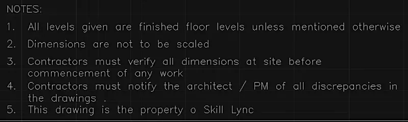
-After drawing the table we have to select the Mtecxt command to enter the notes and project details.
-And the text height will be kept to 8", and its the standard text height for entering the details of the project in the table.

OUTPUT:
*Drawing template is created as shown in the figure
q4)
Aim:
-To create the list of drawing schedule and to be listed in detail.
Introduction:
-A schedule of drawings is an itemised list of drawings required for a building project.
-It can be included as part of an invitation to tender, or may be prepared as part of a design management plan.
-A schedule of drawings may include all the drawings required for a project, or on larger, more complex projects, it may be specifically prepared for a certain discipline, specialist or for a particular aspect of the works
Commands used:
-Limits command
-Table command
-Single text command
-Extend command
-Dimlinear command
Procedure:
Step-1
-First off all we have to open the autocad and set the limits and units.
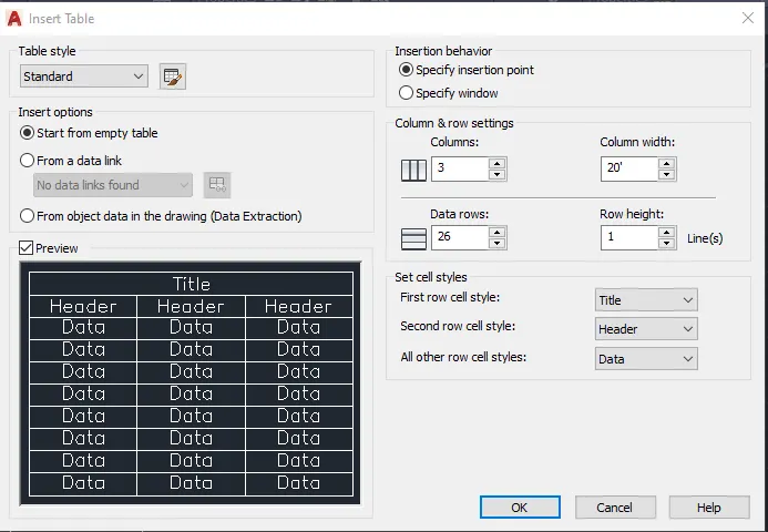
-Next we have to enter the Table command for creating the list of drawing schedules.
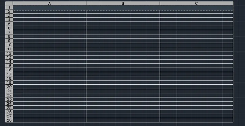
-After entering the table command the table setting screen will be displayed as shown in figure.
Step:2
-Next we use the single text command for texting in the table.
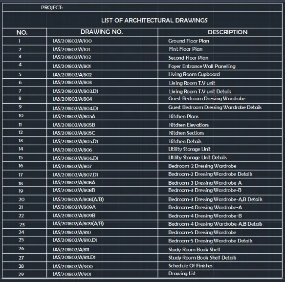
-After entering the details of list of drawing schedule, click on the outside of the table.
-Then the list of drawing schedule is listed in detail, as shown in below table.
OUTPUT:
*The list of drawing schedule is created as shown
q5)
AIM:
-To Create the Beam detail as shown in the figure and provide text for Top level and Ground level wherever given.
INTRODUCTION:
PROCEDURE:
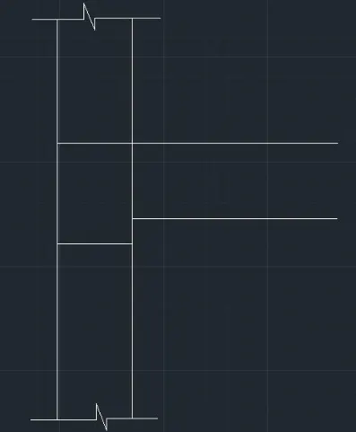
-Select line from the ribbon tab.
-Specify the starting point as (0,0) in the command prompt and press enter.
-Specify the next point as (@0,3") in the command prompt and press enter.
-Specify the next point as (@0,3") in the command prompt and press enter.
-Specify the next point as (@0,9") in the command prompt and press enter.
-Specify the next point as (@0,2.4') in the command prompt and press enter.
-Specify the next point as (@9"0) in the command prompt and press enter.
-Specify the next point as (@0,-2.4') in the command prompt and press enter.
-Specify the next point as (@0,-9") in the command prompt and press enter.
-Specify the next point as (@0,-3") in the command prompt and press enter.
-Specify the next point as (@0,-3') in the command prompt and press enter.
-Specify the next point as (@-9"0) in the command prompt and press enter.
-Type "line" in the command prompt and press enter.
-Specify the starting point as (0,3') in the command prompt and press enter.
-Specify the next point as (@9"0) in the command prompt and press enter.
-Type "line" in the command prompt and press enter.
-Specify the starting point as (0,4') in the command prompt and press enter.
-Specify the next point as (@9",0) in the command prompt and press enter.
-Press "esc".
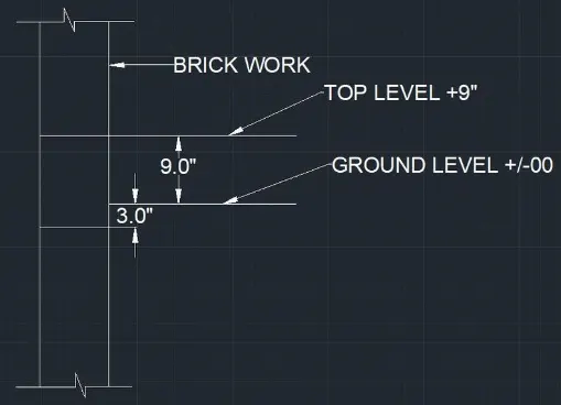
-Select dimension tool from ribbon tab to measure the dimensions.
-Select the first point and drag the pointer to specify the next point.
-Now the tool displays the dimension
-Similarly to type the given text in the workspace use text tool.
-Select the Annotation tool from ribbon tab.
-From the drop down list, select the "leader
-Click on the cursor to start the leader and adjust the height using cursor.
-Enter the text as "Ground level +/-00".
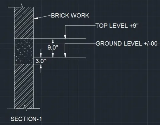
-Type "hatch" in the command prompt and press enter.
-Hatch creation tool box opens.
-From the pattern menu, select the suitable hatch as given in the figure to represent brick work.
-Move the pointer to the closed area to be hatched and click to hatch the layer.
-Adjust the scale to view the hatch.
-Type "hatch" in the command prompt and press enter.
-Hatch creation tool box opens.
-From the pattern menu, select the suitable hatch as given in the figure to represent concrete.
-Move the pointer to the closed area to be hatched and click to hatch the layer.
-Adjust the scale to view the hatch.
-Similarly to type the given text in the workspace use text tool.
-Select the Annotation tool from ribbon tab.
-From the drop down list, select the leader Click on the cursor to start the leader and adjust the height using cursor Enter the text as TOP LEVEL9 TOP LEVEL +9 Ground level
-Similarly to type the given text in the workspace use text tool.
-Select the Annotation tool from ribbon tab.
-From the drop down list, select the leader Click on the cursor to start the leader and adjust the height using cursor Enter the text as BRICKWORK.
-Select the text tool from ribbon tab.
-From the drop down list, select the "single line" Click on the cursor to start entering the text. Enter the text as "Section 1".
OUTPUT:
*The Beam detail is created as shown in the figure and text representation as shown in the figure