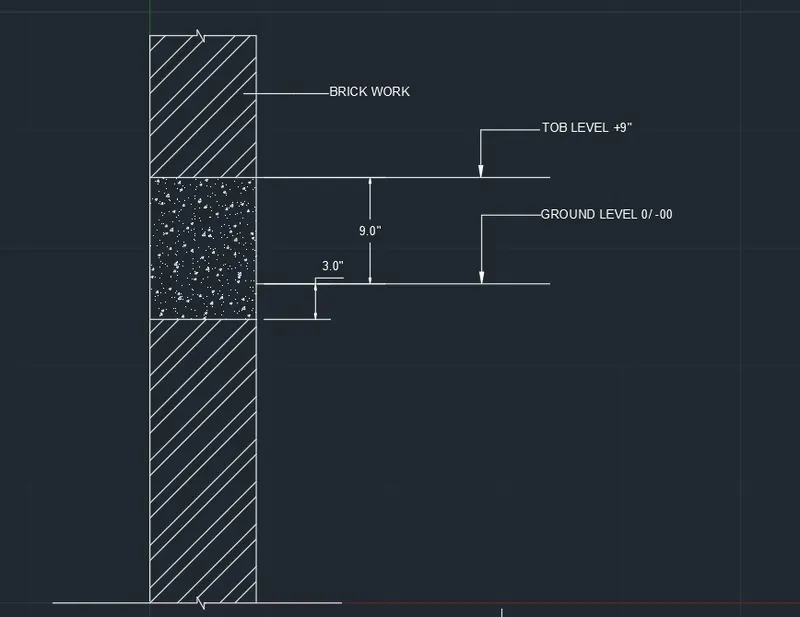
Creation of Column Schedule and Drawing Template using AutoCad
1. COLUMN SCHEDULE PREPARATION
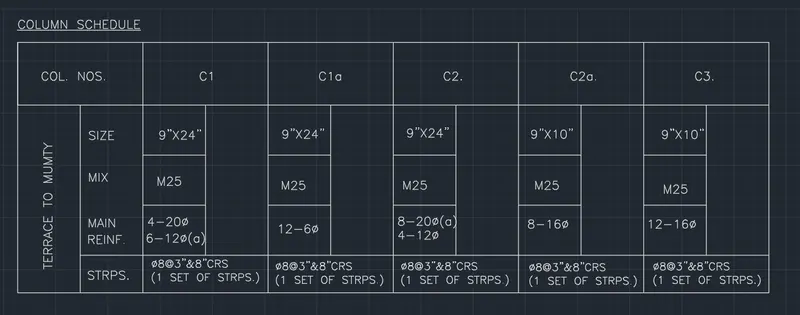
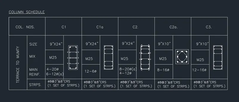
Aim: To create a column schedule with the help of lines as shown in the figure above in AutoCAD.
Introduction:- The desired column schedule is created in AutoCAD using primarily the Line and Text tool. The procedure of drawing is explained in detail with diagrams of each step and the final result is given.
Procedure:
STEP 1
- Go to START MENU, select AutoCAD
- In the Command line type in: STARTUP
- Enter new value of startup: 1
- Go to Application Menu and select New
- In the 'Create New Drawing' dialog box, we do the Advanced Setup and select the 'Engineering' unit of measurement and select precision as '0'-0":
- Set the limits by entering LIMITS in the Command tab. The lower-left corner is specified as '0.0",0'0.0"; and the upper-right corner is specified as 500',500,
- Enter 'UNITS' command in the command tab.
- In the Drawing Units dialog box, select 'Engineering' in Type;'0'-0" 'in Precision; and 'Inches' in Insertion scale.
- Click on 'OK
STEP 2
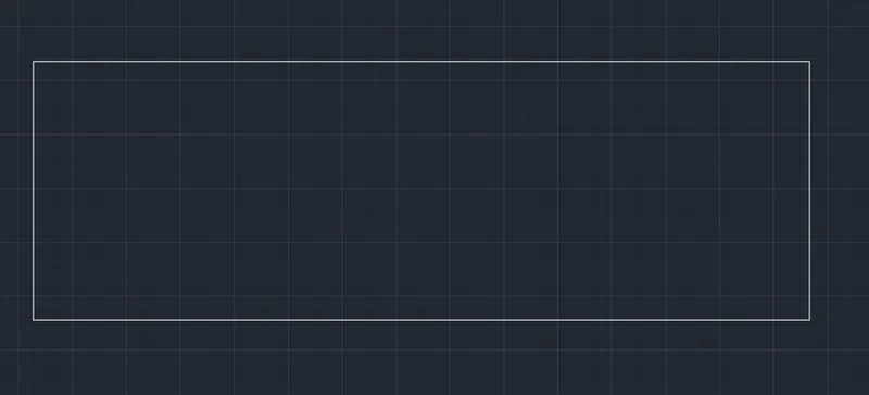
- Select the Line tool by entering 'LINE' command in the command tab.
- Specify the first point as 0,0 in the command line.
- Specify the coordinate of next point as @60'0' in the command line.
- Specify the coordinate of next point as @0',20' in the command line.
- Specify the coordinate of next point as @60;0' in the command line.
- Click Close' on the command line.
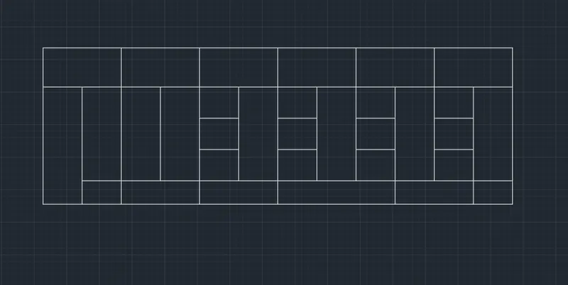
- Select the Offset tool by entering 'OFFSET command in the command tab.
- Enter 5' as offset distance in the command line.
- Select the top horizontal line of the above drawing.
- Specify the point on the downward side of the line to offset.
- Repeat the offset command, specify a distance of 3' and select the bottom horizontal line and click on the upper side of the line to offset.
- Repeat the offset command, specify a distance of 4' and select the top ofsetted horizontal line and click on the downward side of the line and offset twice.
- Repeat the offset command, specify a distance of 5' and select the left vertical line and click on the inside of the line to offset for 11 times to create the columns
- Press 'Esc' to cancel the OFFSET command.
- Select the Trim tool by entering 'TR' command in the command tab.
- Press ENTER.
- Select Edge option; and click on No Extend.
- Select the unwanted lines to trim.
- Press 'Esc' to cancel the TRIM command.
STEP 3
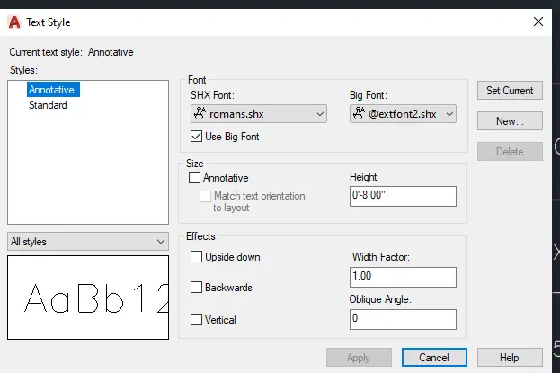
- Enter 'ST' command in the command tab to open the Text Style dialog box.
- Select the Font Name as romans.shx; Text Height as 8",
- Enter 'DTEXT' command in the command line.
- Specify the start point of text as required.
- Specify angle of rotation of text as 0.
- Enter the name of the table i.e. 'COLUMN SCHEDULE
- Click Enter and press Esc.
- Again enter 'DTEXT command in the command line.
- Specify the start point of text as required.
- Specify angle of rotation of text as 90.
- Enter the row heahing as i.e. TERRACE TO MUMTY:
- Click Enter and press Esc.
- Enter 'DTEXT' command in the command line.
- Specify the start point of text as required.
- Specify angle of rotation of text as 0.
- Enter the column heading i.e. 'COL. NOS:
- Click Enter and press Esc.
- Enter 'Co' command in the command line.
- Select the text to copy.
- Specify the base point and copy the text box to required locations.
- Press Esc to cancel the copy command.
- Enter 'ED' command in the command line to edit the texts as required.
- Select the annotation object to edit and make necessary changes.
- Press Esc to cancel the textedit command.
STEP 4
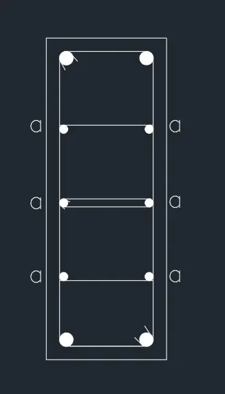
- For creating column C1, select the Rectangle tool by entering 'REC' command in the command tab.
- Specify the first point of the rectangle.
- Select Dimensions option in the command line.
- Specify length of rectangle as 9" in the command line.
- Specify width of rectangle as 24" in the command line.
- Move the cursor towards the upward and click ENTER.
- Select the Offset tool by entering OFFSET' command in the command tab.
- Enter 1" as offset distance in the command line.
- Select the recteangle created previously.
- Click on the inside of the rectangle.
- Press 'Esc' to cancel the OFFSET command.
- Select the Circle tool by entering 'C' command in the command tab, specify the centre of the circle.
- Specify radius as 0.5"(representing bars of 20 mm dia.).
- Again select the circle tool and draw a circle of radius 0.3" (representing bars of 12 mm dia.).
- Enter 'Co' command in the command line.
- Select the circle of radius 0.5" and copy it to all desired locations do the same for the circle of radius 0.3"
- Select the fillet tool by entering 'F' in the command line.
- Specify a radius of 0.5"
- Fillet all the corners of the inner rectangle after exploding it.
- Select the Line tool by entering ‘LINE' command in the command tab.
- Draw lines to define the stirrups.
- Press 'Esc' to cancel the Line tool.
- Next enter the 'DTEXT' command and type the letter 'a' to highlight the bars of diameter 12 mm.
- Click Enter and press Esc.
STEP 5
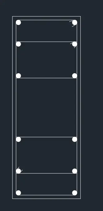
- For creating column C1a, select the Rectangle tool by entering 'REC' command in the command tab.
- Specify the first point of the rectangle.
- Select Dimensions option in the command line.
- Specify length of rectangle as 9" in the command line.
- Specify width of rectangle as 24" in the command line.
- Move the cursor towards the upward and click ENTER.
- Select the Offset tool by entering 'OFFSET' command in the command tab.
- Enter 1" as offset distance in the command line.
- Select the rectangle created previously.
- Click on the inside of the rectangle.
- Press 'Esc' to cancel the OFFSET command.
- Select the Circle tool by entering 'C' command in the command tab, specify the centre of the circle.
- Specify radius as 0.4"(representing bars of 16 mm dia.).
- Enter 'Co' command in the command line.
- Select the circle of radius 0.4" and copy it to all desired locations.
- Select the fillet tool by entering 'F' in the command line.
- Specify a radius of 0.5".
- Fillet all the corners of the inner rectangle after exploding it.
- Select the Line tool by entering ‘LINE' command in the command tab.
- Draw lines to define the stirrups.
- Press 'Esc' to cancel the Line tool.
STEP 6
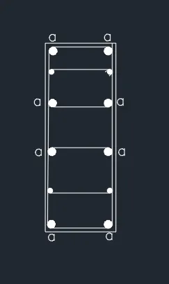
- For creating column C2, select the Rectangle tool by entering 'REC' command in the command tab.
- Specify the first point of the rectangle.
- Select Dimensions option in the command line.
- Specify length of rectangle as 9" in the command line.
- Specify width of rectangle as 24" in the command line.
- Move the cursor towards the upward and click ENTER.
- Select the Offset tool by entering OFFSET' command in the command tab.
- Enter 1" as offset distance in the command line.
- Select the recteangle created previously.
- Click on the inside of the rectangle.
- Press 'Esc' to cancel the OFFSET command.
- Select the Circle tool by entering 'C' command in the command tab, specify the centre of the circle.
- Specify radius as 0.5"(representingbars of 20 mm dia.).
- Again select the circle tool and draw a circle of radius 0.3" (representing bars of 12 mm dia.).
- Enter 'CO' command in the command line.
- Select the circle of radius 0.5" and copy it to all desired locations.
- Select the fillet tool by entering 'F' in the command line.
- Specify a radius of 0.5"
- Fillet all the corners of the inner rectangle after exploding it.
- Select the Line tool by entering 'LINE' command in the command tab.
- Draw lines to define the stirrups.
- Press 'Esc' to cancel the Line tool.
- Next enter the 'DTEXT' command and type the letter 'a' to highlight the bars of diameter 20 mm.
- Click Enter and press Esc.
STEP 7
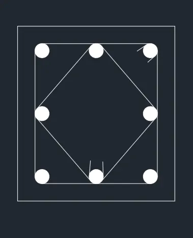
- For creating column C2a, select the Rectangle tool by entering 'REC' command in the command tab.
- Specify the first point of the rectangle.
- Select Dimensions option in the command line.
- Specify length of rectangle as 9" in the command line.
- Specify width of rectangle as 10" in the command line.
- Move the cursor towards the upward and click ENTER.
- Select the Offset tool by entering OFFSET' command in the command tab.
- Enter 1" as offset distance in the command line.
- Select the recteangle created previously.
- Click on the inside of the rectangle.
- Press 'Esc' to cancel the OFFSET command.
- Select the Circle tool by entering 'C' command in the command tab, specify the centre of the circle.
- Specify radius as 0.4"(representing bars of 16 mm dia.).
- Enter 'CO' command in the command line.
- Select the circle of radius 0.4" and copy it to all desired locations.
- Select the fillet tool by entering 'F' in the command line.
- Specify a radius of 0.4".
- Fillet all the corners of the inner rectangle.
- Select the Line tool by entering 'LINE' command in the command tab.
- Draw lines to define the stirrups.
- Press 'Esc' to cancel the Line tool.
STEP 8.
- For creating column C3, select the Rectangle tool by entering 'REC' command in the command tab.
- Specify the first point of the rectangle.
- Select Dimensions option in the command line.
- Specify length of rectangle as 9" in the command line.
- Specify width of rectangle as 21" in the command line.
- Move the cursor towards the upward and click ENTER.
- Select the Offset tool by entering OFFSET' command in the command tab.
- Enter 1" as offset distance in the command line.
- Select the recteangle created previously.
- Click on the inside of the rectangle.
- Press 'Esc' to cancel the OFFSET command.
- Select the Circle tool by entering 'C' command in the command tab, specify the centre of the circle.
- Specify radius as 0.4"(representing bars of 16 mm dia.).
- Enter 'CO' command in the command line.
- Select the circle of radius 0.4" and copy it to all desired locations.
- Select the fillet tool by entering 'F' in the command line.
- Specify a radius of 0.4".
- Fillet all the corners of the inner rectangle.
- Select the Line tool by entering 'LINE' command in the command tab.
- Draw lines to define the stirrups.
- Press 'Esc' to cancel the Line tool.
STEP 9
- Enter 'CO' command in the command line.
- Select the coliumn sections created in steps 4, 5, 6, 7, 8.
- Copy the column sections to the Table cretaed in step 3.
- Press Esc.
- Save the drawing.
RESULT
2.WINDOW SCHEDULE
AIM: To create the window schedule using AutoCAD.
INTRODUCTION: The window schedule using AutoCAD is created by Lines. The procedure and result should be written after creating the window schedule.
PROCEDURE:
STEP 1:
- Open the AutoCAD software and click start Drawing tab.
- Enter UNITS in command box.
- Select ENGINEERING in TYPE, O'O" in PRECISION and INCHES in UNITS TO SCALE INSERTED CONTENT. Press OK.
- Switch on ORTHOMODE.
- Enter Lin command box.
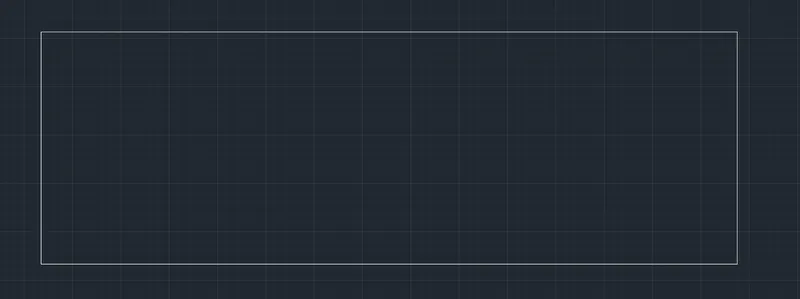
- Enter 60'0' as first point.
- Enter 0,20' as next point.
- Enter @-60',0' as next point.
- Enter @O', -20' as next point.
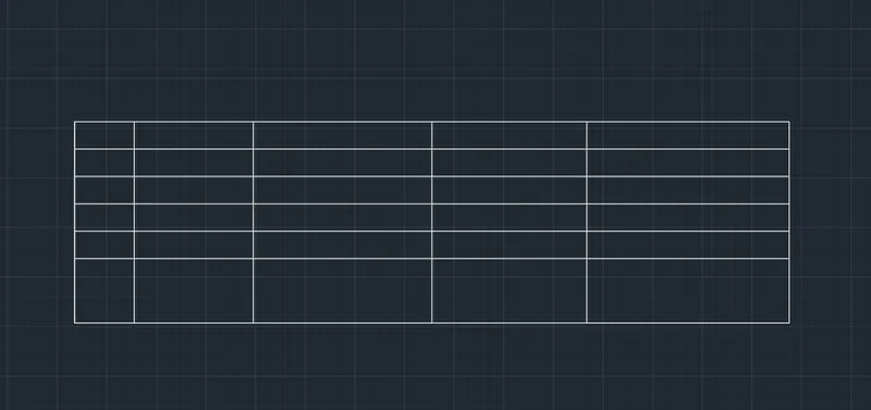
STEP 2:
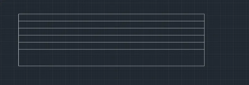
- Enter O in command box.
- Enter 2.3' as offset distance.
- Select the upper horizontal line.
- Drag it downwards.
- Repeat the same step four more times.
STEP 3:
- Enter O in command box.
- Type 5' as offset distance.
- Select the left line and drag inwards.
- Enter O in command box.
- Type 10' as offset distance.
- Select the 5' line and drag inwards.
- Enter O in command box.
- Type 15' as offset distance.
- Select the 10' line and drag inwards.
- Enter O in command box.
- Type 13' as offset distance.
- Select the 15' line and drag inwards.
- Enter O in command box.
- Type 17' as offset distance.
- Select the 13' line and drag inwards.
STEP 4:
- Enter ST in command box.
- Select romans.shx in FONT NAME and HEIGHT as 8". Click OK.
- Click ANNOTATION tab and Select SINGLE LINE in RIBBON.
- Enter the text height as 8" and rotation angle as 0.
- Select MULTILINE TEXT in RIBBON.
- Enter the dimensions.
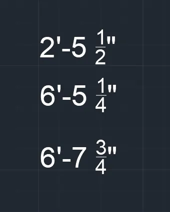
- Click Tab after entering 1/2, 1/4 and 3/4.
- Enter TEXTEDIT in command box to edit the text.
- Enter M in command box to move the text.
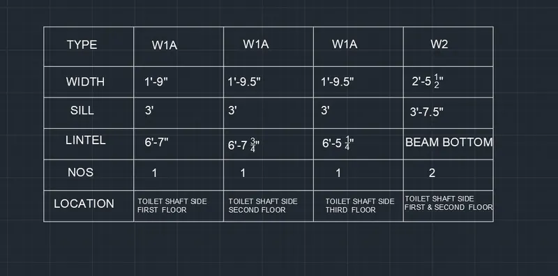
RESULT:
The Window schedule is created by lines using AutoCAD. The step-by-step procedure for creating the window schedule is also explained. The Dimension is also entered in the diagram.
3.DRAWlNG TEMPLATE
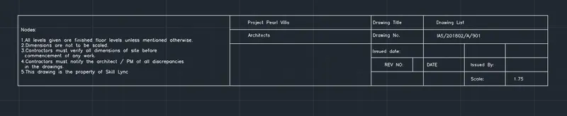
AIM: To create the drawing template using AutoCAD.
INTRODUCTION: The drawing template using AutoCAD is created by Lines. The procedure and result should be written after creating the drawing template.
PROCEDURE:
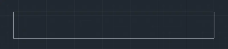
STEP 1:
- Open the AutoCAD software and click start Drawing tab.
- Enter UNITS in command box.
- Select ENGINEERING in TYPE, 0'0" in PRECISION and INCHES in UNITS TO SCALE INSERTED CONTENT. Press 0K
- Switch on ORTHOMODE.
- Enter L and type 0,0 in command box.
- Enter 150',0' as first point.
- Enter 0',20' as next point
- Enter as next point.
- Enter 00', -20' as next point.
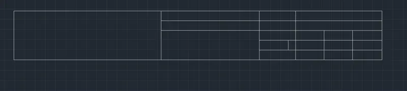
STEP 2:
- Enter O in command box.
- Enter 60' as offset distance.
- Select the left line and drag it inwards.
- Enter O in command box.
- Enter 40' as offset distance.
- Select the 60' line and drag it inwards.
- Enter O in command box.
- Enter 50' as offset distance.
- Select the 40' line and drag it inwards.
- Enter O in command box.
- Enter 4' as offset distance.
- Select the upper line and drag it inwards.
- Repeat the same step four more times.
- Enter O in command box.
- Enter 15' as offset distance.
- Select the 40' line and drag it inwards.
- Enter O in command box.
- Enter 11'6" as offset distance.
- Select the 15' line and drag it inwards.
- Repeat the same step one more time.
- Enter O in command box.
- Enter 12' as offset distance.
- Select the 11'6" line and drag it inwards.
- Enter O in command line.
- Enter 3' as offset distance.
- Select the 15' line and drag it left side.
STEP 3:
- Enter ST in command box. Select romans.shx in FONT NAME and HEIGHT as 8".
- Click OK.
- Click ANNOTATION tab and Select SINGLE LINE in RIBBON.
- Enter the text height as 8" and rotation angle as O.
- Enter the text in the drawing template.
- Enter TEXTEDIT in command box to edit the text.
- Enter M in command box to move the text.
RESULT:
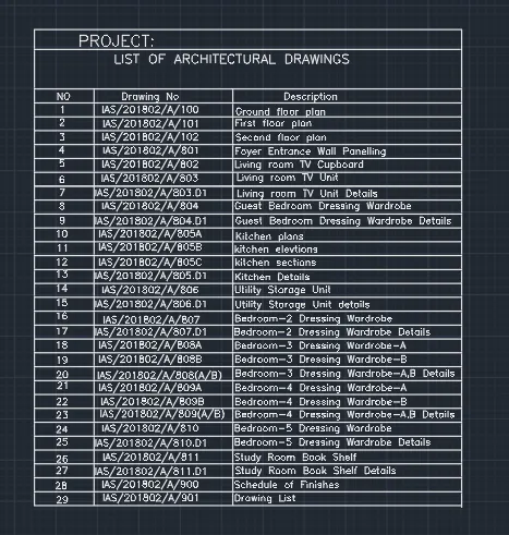
4.LIST OF DRAWING SCHEDULE
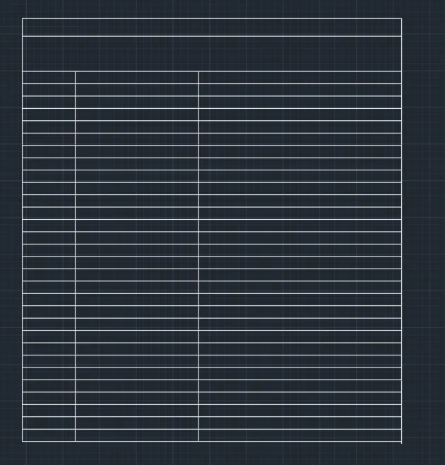
AIM: To create the list of drawing schedule using AutoCAD.
INTRODUCTION: The list of drawing schedule using AutoCAD is created by Lines. The procedure and result should be written after creating the list of drawing schedule.
PROCEDURE:
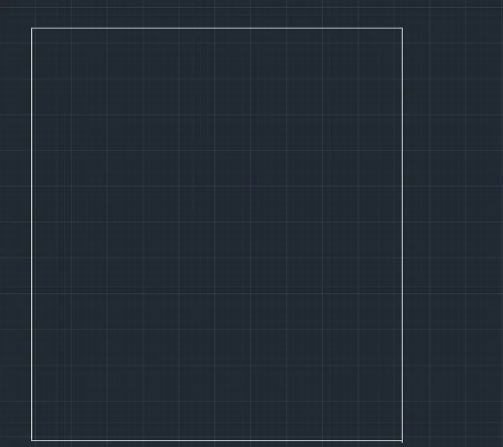
STEP 1:
- Open the AutoCAD software and click start Drawing tab.
- Enter UNITS in command box.
- Select ENGINEERING in TYPE, O'0" in PRECISION and INCHES in UNITS TO SCALE INSERTED CONTENT
- Press OK.
- Switch on ORTHOMODE.
- Enter L and type 0,0 in command box.
- Type 200,0' in command box.
- Type 0,250' in command box.
- Type @-200,0' in command box.
- Type @0,-250' in command box.
STEP 2:
- Enter O in command box.
- Enter 30' as offset distance.
- Select the left line and drag it inwards.
- Enter O in command box.
- Enter 60' as offset distance.
- Select the 30' line and drag it inwards.
- Enter O in command box.
- Enter 110' as offset distance.
- Select the 60' line and drag it inwards.
- Enter O in command box.
- Enter 10' as offset distance.
- Select the upper line and drag it inwards.
- Enter O in command box.
- Enter 20' as offset distance.
- Select the 10' line and drag it inwards.
- Enter O in command box.
- Enter 7' as offset distance.
- Select the 20' line and drag it inwards.
- Repeat the same step for 29 times
STEP 3:
- Enter ST in command box.
- Select romans.shx in FONT NAME and HEIGHT as 8" Click OK.
- Click ANNOTATION tab and Select SINGLE LINE in RIBBON.
- Enter the text height as 8" and rotation angle as O.
- Enter the text in the drawing template.
- Enter CO in command box.
- Click ARRAY and enter 29.
- Select the text and press ENTER
- Enter TEXTEDIT in command box to edit the text.
- Enter M in command box to move the text.
RESULT:
The List of Drawing schedule is created by lines using AutoCAD. The step-by-step procedure for creating the list of drawing schedule is also explained. The Dimension is also entered in the diagram.
5.BEAM DETAIL
Aim: To create the beam detail with the help of Line command as shown in the figure above in AutoCAD.
Introduction: The desired beam detail is created in AutoCAD using primarily the Line tool. The procedure of drawing is explained in detail with diagrams of each step and the final result is given.
Procedure:
STEP 1
- Go to START MENU, select AutoCAD.
- In the Command line type in: STARTUP [ENTER]
- Enter new value of startup: 1 .
- Go to Application Menu and select New
- In the Create New Drawing dialog box, we do the Advanced Setup and select the 'Engineering' unit of measurement and select precision as '0'-0"
- Set the limits by entering LIMITS in the Command tab. The lower-left corner is specified as 0'0.0",0'0.0"; and the upper-right corner is specified as 100,100'.
- Enter 'UNITS' command in the command tab.
- In the Drawing Units dialog box, select 'Engineering' in Type;'0'-0" in Precision; and 'Inches'in Insertion scale.
- Click on 'OK
STEP 2
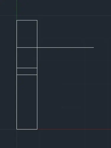
- Select the Line tool by entering 'LINE' command in the command tab.
- Specify the first point as 0,0 in the command line.
- Specify the coordinate of next point as @0,4' in the command line.
- Specify the coordinate of next point as @9",0' in the command line.
- Specify the coordinate of next point as @0',-4' in the command line.
- Click Close' on the command line.
- Select the Offset tool by entering OFFSET' command in the command tab.
- Enter l' as offset distance in the command line.
- Select the top horizontal line of the above drawing.
Specify the point on the downward side of the line to offset. - Extend the offsetted line.
- Repeat Offset again, select the last offsetted line, specify a distance of 9", and click downwards.
- Repeat offset again, select the last offsetted line, specify a distance of 3", and click downwards.
- Press Esc.
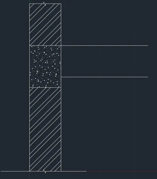
- Select the Line tool by entering 'LINE' command in the command tab.
- Draw lines to represent the cut edges of the wall section.
- Press 'Esc' to cancel the Line tool.
- Select the Trim tool from the Ribbon, and trim the unwanted lines.
- Press Esc.
- Enter 'H' in the command line.
- Select STEEL Pattern, and click on the desired locations.
- Next select the AR-CONC Pattern and click inside the mid section.
STEP 3
- Enter 'DIMSTY' command in the command tab to open the Dimension Style Manager dialog box.
- Click on the Modify tab.
- Under the Text option change the Text height to 3".
- Click OK.
- Then click on Set Current and Close the dialog box.
- Select the Dimension tool by entering 'DIM' in the command line
- Select the first point and second point of the object to be measured, then drag the dimension line to the desired location. Repeat for all the objects to be measured.
- Press Esc to cancel the Dimension tool.
- Enter 'ST' command in the command tab to open the Text Style dialog box.
- Select the Font Name as romans.shx;
- Text Height as 3".
- Enter 'MTEXT command in the command line.
- Specify the start point of text as required.
- Create the text box.
- Type in the required text.
- Press Enter.
- Enter 'QLEADER' in the command prompt.
- Draw leader lines as required.
- Press Esc.
- Enter 'CO' in the command line.
- Select the text and copy it to the desired locations beside the Quick leader lines.
- Press Esc.
- Enter 'ED' in the command line.
- Edit the texts.
- Save the drawing.
RESULT: