Creation of Column Schedule and Drawing Template using AutoCad
CHALLENGE-5
PREPARED BY- MEGHA GUPTA
Creation of Column Schedule and Drawing Template using AutoCAD.
Aim: Aim of the challenge is to create the column schedule and drawing template in AutoCAD.
Introduction: In this project column schedule and drawing template have been created using various tools available in AutoCAD.
To create the schedule line command has been used to draw the tables and annotation command to write the text. Hatch command is used for showing the brick wall and concrete. Roman.shx text type has been used in this project with height of the text as 8”.
Procedure followed for creating the schedule and drawing template has been discussed below with each of the drawing.
- Create a column schedule as shown in the figure.
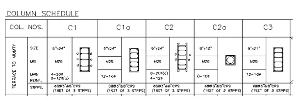
Fig. 1: Column Schedule
Procedure followed for creating Column Schedule:
- Select the current drawing units as engineering.
- Select line command from the toolbar.
- Create the table using line command referring Fig. 1.
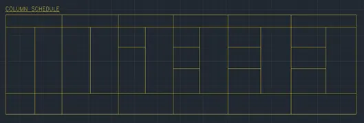
Fig. 2
- Go to annotation toolbar and then select the type of font as roman.shx.
- Select the height of font as 8”.
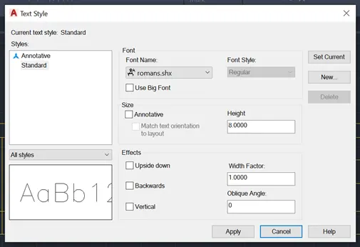
Fig. 3
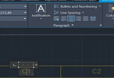
Fig. 4
- Now, using annotation text has been added referring the Fig. 1.
- Text position has been justified to left using justification toolbar.
- Column detailing showing reinforcement of cross section has been created using line command whereas reinforcement cross section was shown using circle command.
- Circles have been filled from inside using hatch gradient command to show the bar.
- Symbol toolbar have been used to insert symbols like @, ∅
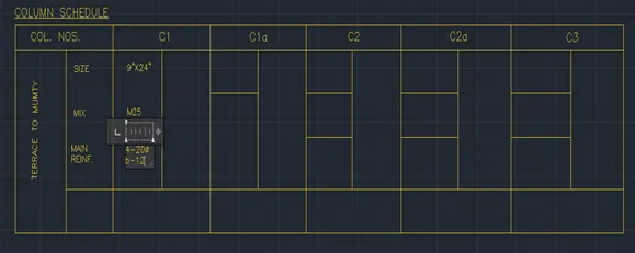
Fig. 5
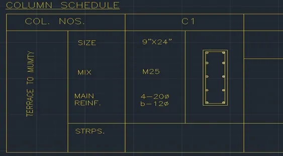
Fig. 6
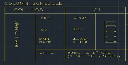
Fig. 7
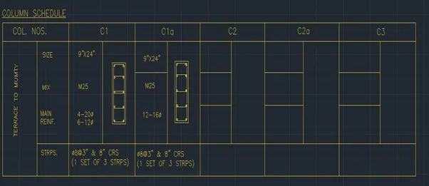
Fig. 8
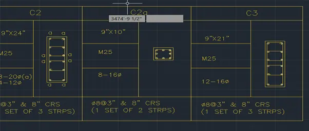
Fig. 9
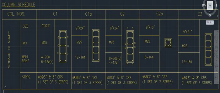
Fig. 10
- Create a window schedule as shown in the figure:
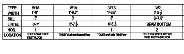
Fig. 11: Window Schedule
Procedure followed for creating Window Schedule:
- Select the current drawing units as engineering.
- Select line command from the toolbar.
- Create the table using line command referring Fig. 11.
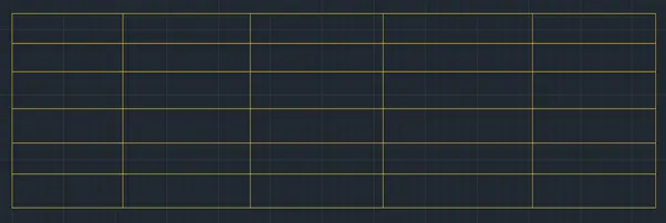
Fig. 12
- Now, using annotation text has been added referring the Fig. 11.
- Text position has been justified to left using justification toolbar.
- Symbol toolbar have been used to insert symbols like @, ∅ etc.
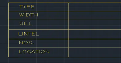
Fig. 13
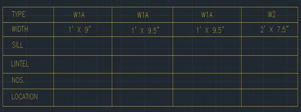
Fig. 14
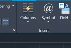
Fig. 15
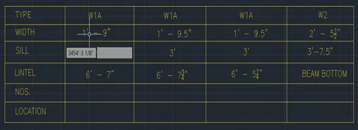
Fig. 16
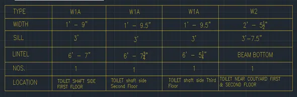
Fig. 17
- Create the drawing template as shown in the figure:
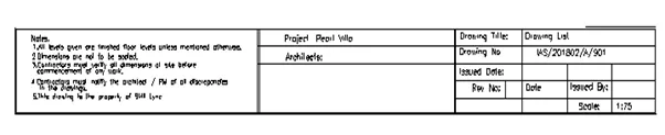
Fig. 18
Procedure followed for creating drawing template:
- Select the current drawing units as engineering.
- Select line command from the toolbar.
- Offset command has been used to create the double lined boundary.
- Create the table using line command referring Fig. 18.
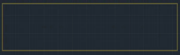
Fig. 19
- Line command has been to create the table similar to Fig. 18.
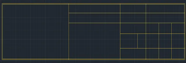
Fig. 20
- Now, using annotation text has been added referring the Fig. 11.
- Text position has been justified to left using justification toolbar.
- shx text type has been used.
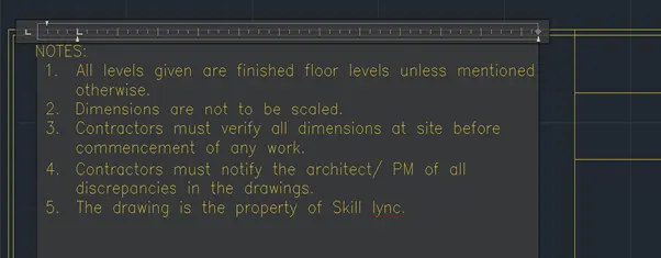
Fig. 21
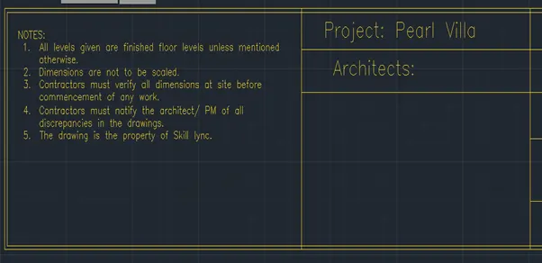
Fig. 22
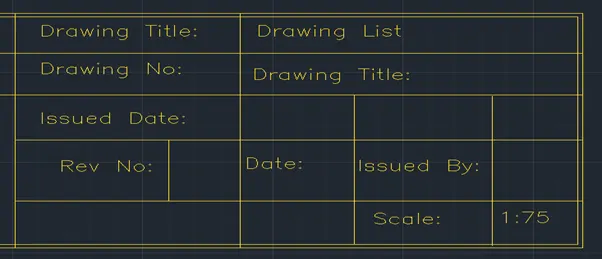
Fig. 23
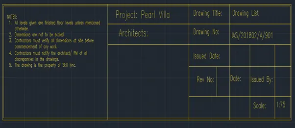
Fig. 24
4. Create the list of drawing schedule as shown in the figure:
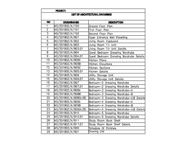
Fig. 25
Procedure followed for creating the list of drawing schedule as per Fig. 25:
- Select the current drawing units as engineering.
- Select line command from the toolbar.
- Offset command has been used to create the rows at same spacing.
- Create the table using line command referring Fig. 25.

Fig. 26
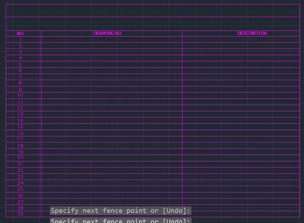
Fig. 27
- Now, using annotation text has been added referring the Fig. 25.
- Text position has been justified to left using justification toolbar.
- shx text type has been used for entire concept except headings. For headings SansSerif type of font has been used.
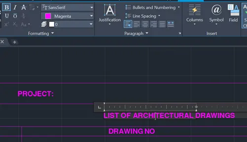
Fig. 28
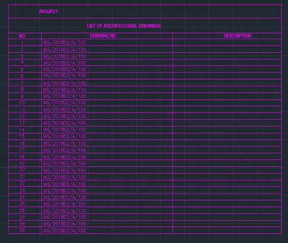
Fig. 29

Fig. 30
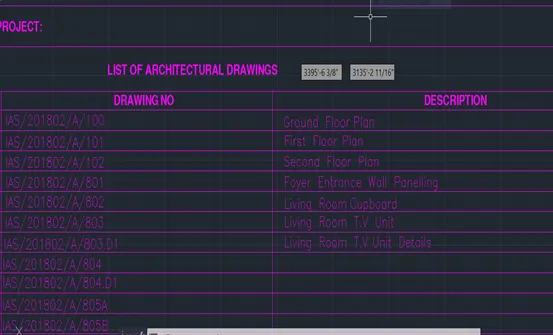
Fig. 31
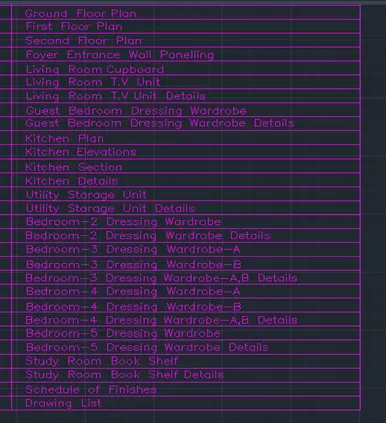
Fig. 32
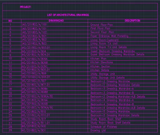
Fig. 33
5. Create the beam detail as shown in the figure and provide text wherever given:
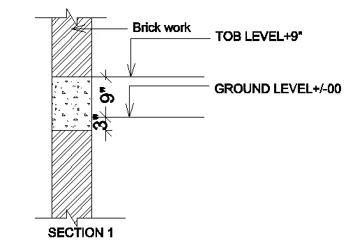
Fig. 34
Procedure followed for creating the list of drawing schedule as per Fig. 34:
- Select the current drawing units as engineering.
- Select line command from the toolbar.
- Create the wall with 9” thickness.
- Create TOB Level and Ground level using offset command.
- Show the continuation of the wall at top and bottom using line command.
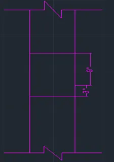
Fig. 35
- Create hatch command to show the brick wall pattern and concrete pattern in the beam.
- SansSerif type of font has been used.
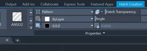
Fig. 36
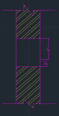
Fig. 37
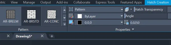
Fig. 38
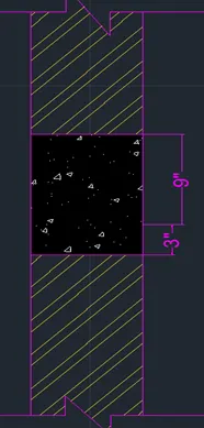
Fig. 39
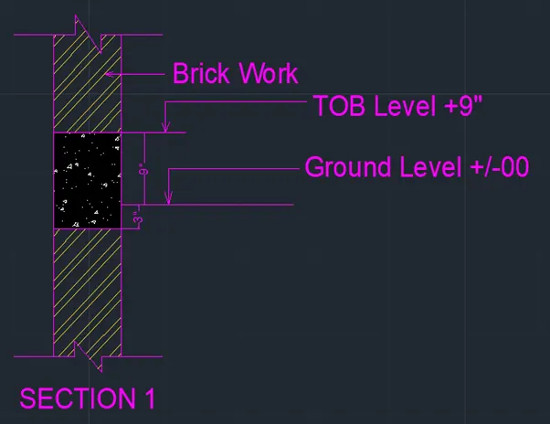
Fig. 40